

Minnesota Oli
-
Posts
101 -
Joined
-
Last visited
-
Days Won
4
Posts posted by Minnesota Oli
-
-
11 hours ago, John E Davies said:
Neat! do you have a link for the flexible insulation material you used in the outside access doors?
You might want to think about sealing off the big screened vent holes in your battery door.
Wouldn’t it be NICE if Oliver would build these trailers with molded in place fiberglass air ducts going through all those locations?
Thanks,
John Davies
Spokane WA
I think it would be great if they would harden there four season trailer by installing the additional duct work, not much extra expense and fairly easy install if it was incorporated in the manufacturing process. Due to the recent trend of switching to lithium batteries we have been reminded of the key role that temperature plays in all forms of batteries. I think if Oliver heated the battery storage compartment and kept it sealed to the inside and vented to the outside they could accommodate any battery option. Then for lithium simply install an insulating material at the opening of the compartment during the winter and remove during the summer. Plus all the other benefits of warmer bathroom and no freeze up worries with the out side wash station, water fill inlets.
To answer your question about the insulation material it was something I had on hand. The vent holes in the battery door I want to play with that during the warmer months to see if I can keep the lithium battery at the proper temperature.
As far as the outside storage compartment door which also covers the outside wash station I did not have to use any additional insulation.
I appreciate the compliment
Paul
-
 1
1
-
-
1 hour ago, mustang said:
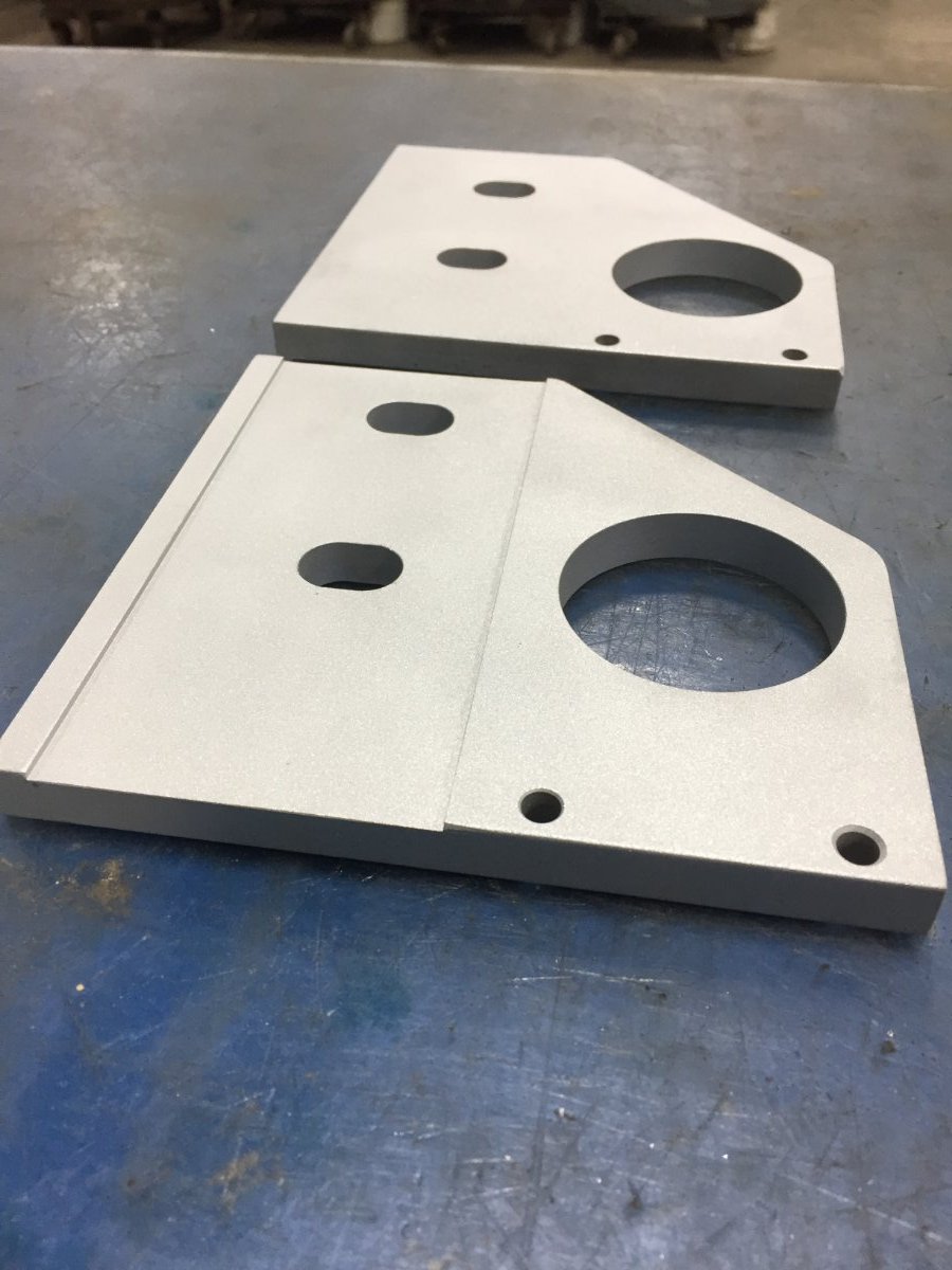
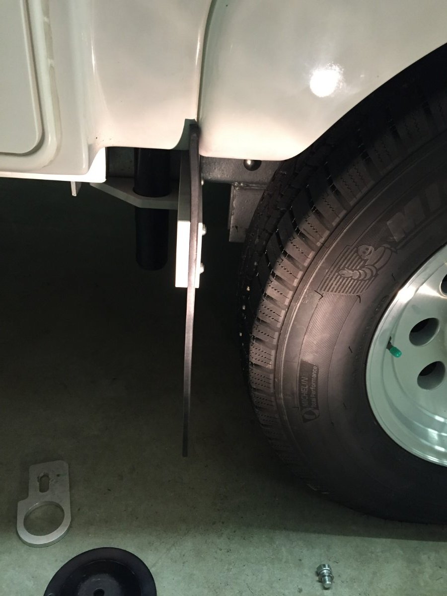
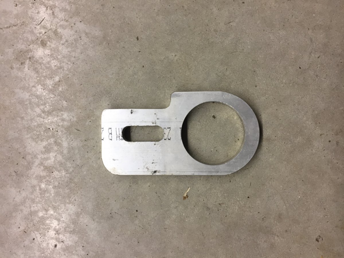
I like your mud flap mod , do you have a pattern or drawing to make bracket? tks ron
I will try to make up some prints and get them posted.
-
4 hours ago, John E Davies said:
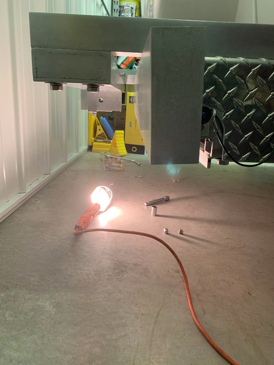
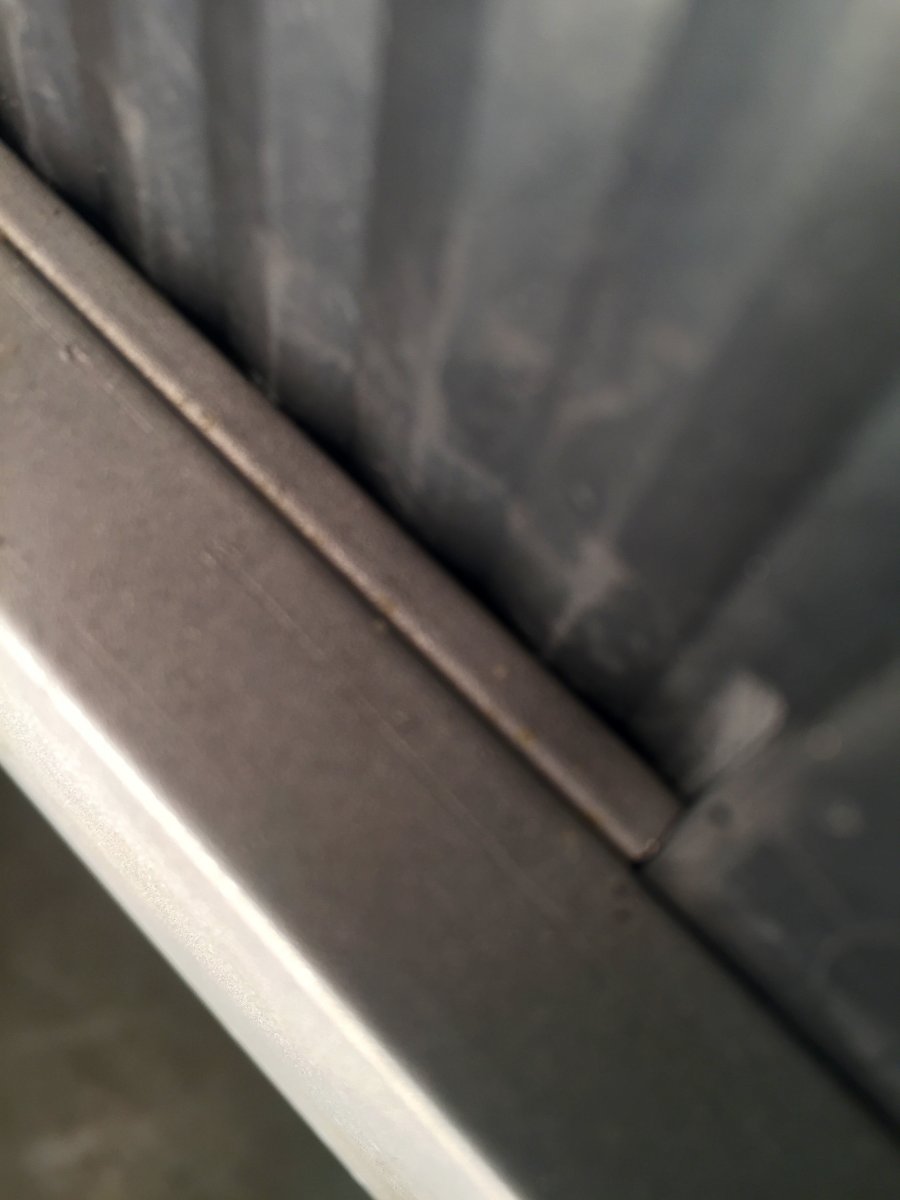
Pretty. I can't tell, where is the 'fuse"? If you whack the side into a big fixed boulder while backing into a campsite, where will the bar break or bend? Will the small screws shear? What size did you choose?
Thanks.
John Davies
Spokane WA
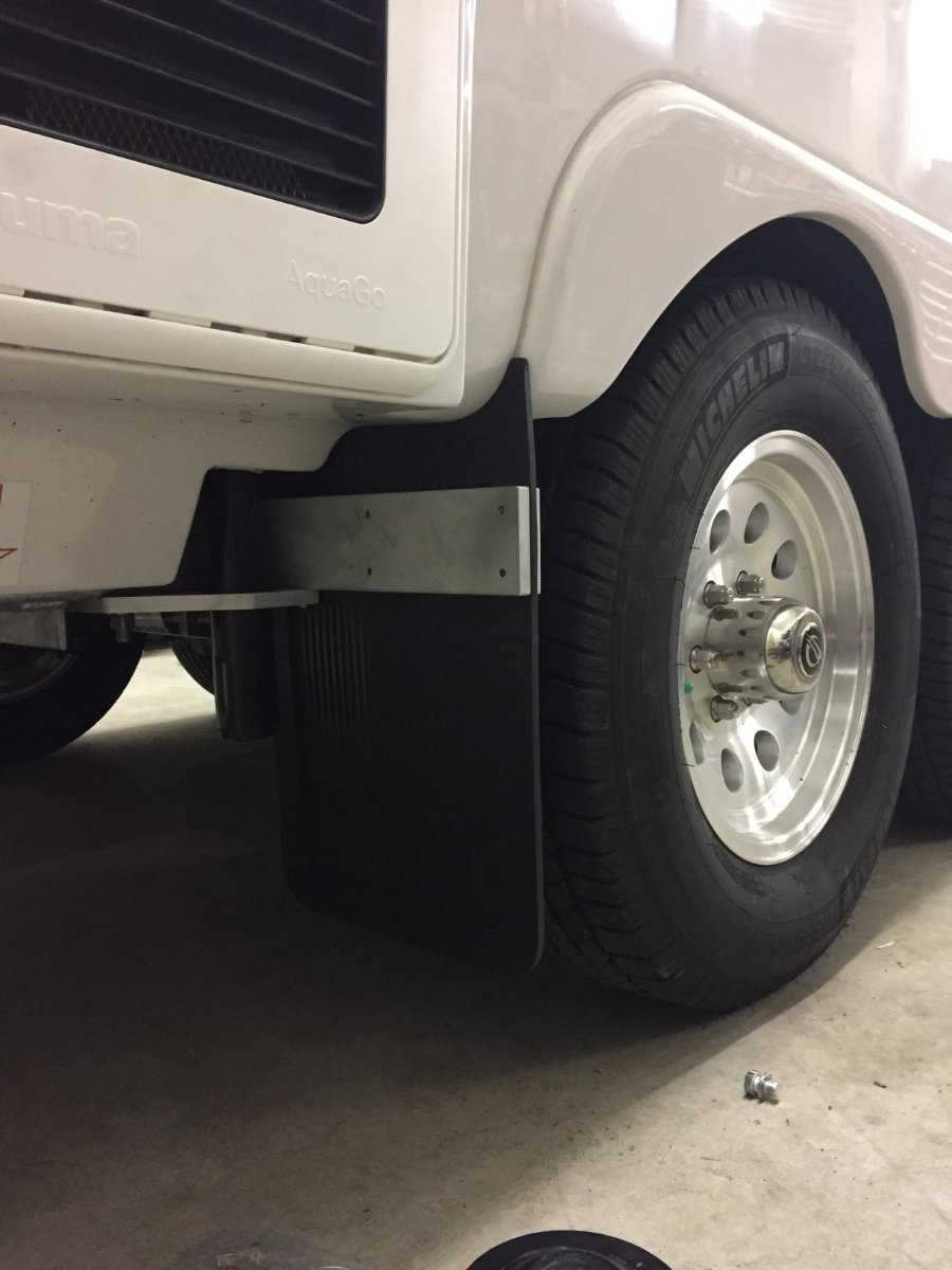
I used two 1/4"-20 and there at the end of a 12" long bar, so I,am thinking they should shear.
-
- Popular Post
- Popular Post
The seed was planted for this furnace mod when we grabbed a canceled reservation three weeks out at a Minnesota State Park. This reservation was mid October and when the date arrived the weather forecast had changed for the worse. We stayed for only two of the three days and we received our first snow of the season, 6 inches of wet snow. We had a non electric site and my batteries were having trouble making it through the night and I was concerned about the water freezing in the Oliver. I have already addressed switching to lithium batteries and posted about it on Oliver Forum. Now I want to share with you what I have done to relieve my worries about water freeze ups in the Oliver, provided that I have a functioning furnace.
I first tried to identify the weak spots and came up with the following.
- Boondocking Inlet
- Outside Wash Station
- Fresh Tank Fill Inlet
- City Water Inlet
- Black Tank Flush Port
- Toilet Water Supply Line
- Hot & Cold Lines Crossing Back Of Oliver
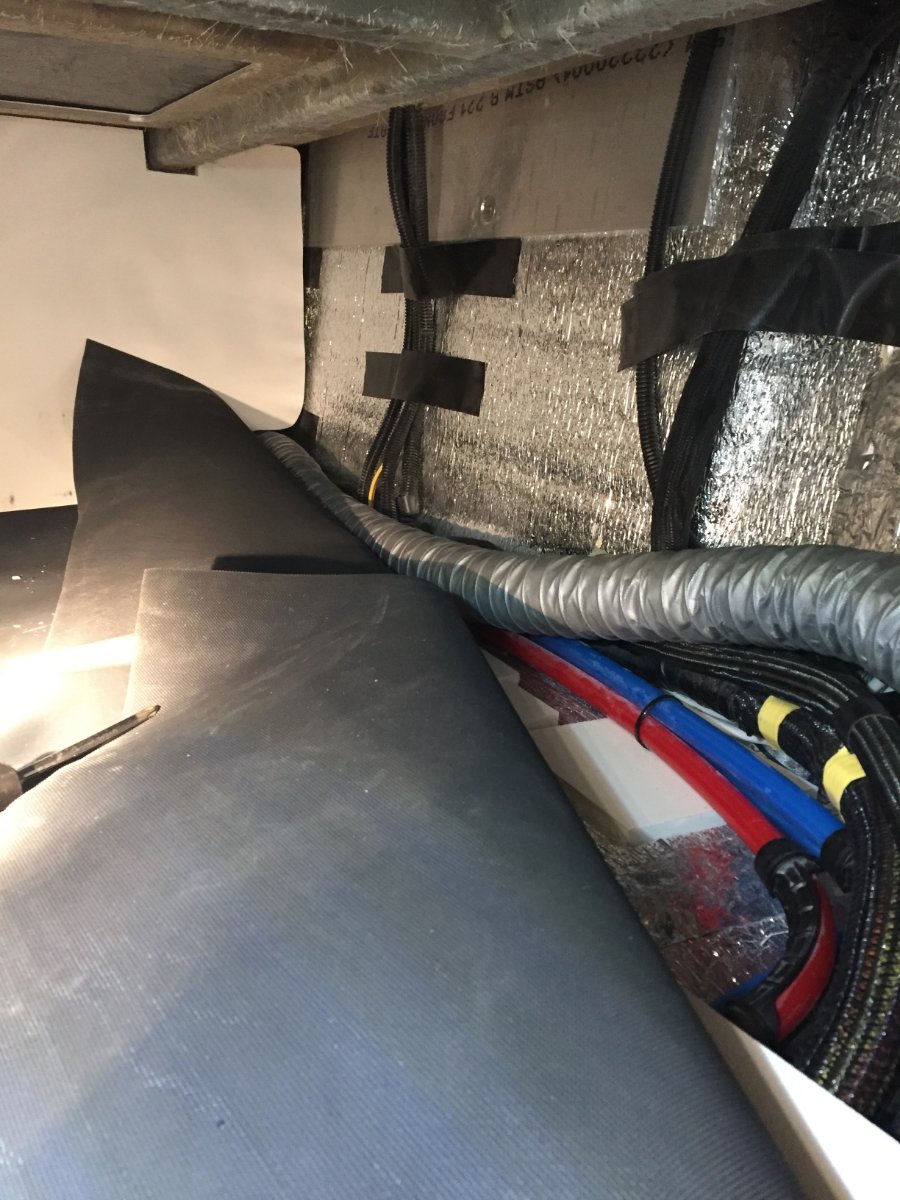
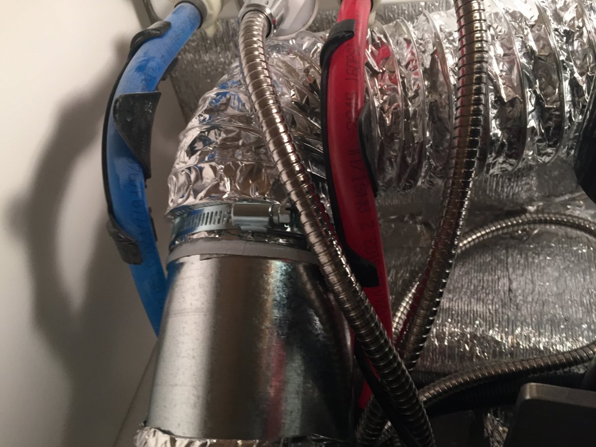
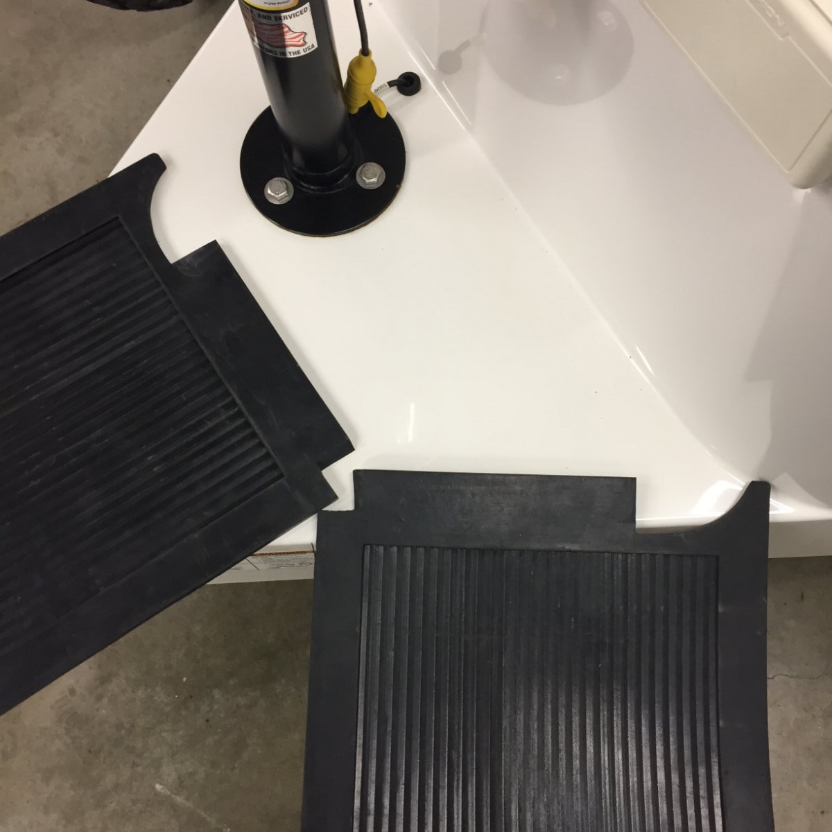
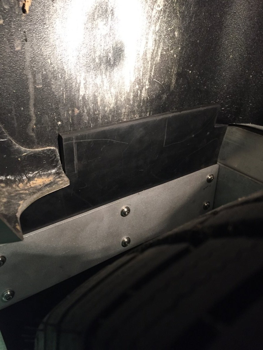
The Oliver has all of it's heat ducts run on the curbside which protect the kitchen and the bathroom faucets from freezing. My plan is to run a 2" ducting along the back to the street side and terminating in to the trough that the water lines run in for the city water inlet, fresh tank fill inlet and outside faucet. This trough also has the check valves for those two inlets and has the floor of the exterior storage compartment covering over the top of it. To get at the trough you will have to remove the back wall of the storage compartment and flip the mat back that covers the floor. This exposes the water lines that come across the back of the trailer and drop into that trough. There is a wall that separates the furnace compartment from storage and extends past the wall you just removed. It has a opening for the water lines and it is large enough to run the 2" duct through it and on top of the water lines across the back and into the trough. Now you can flip the mat back down and they are long enough to cover the water lines and the newly installed 2" duct, then the wall is put back in place.

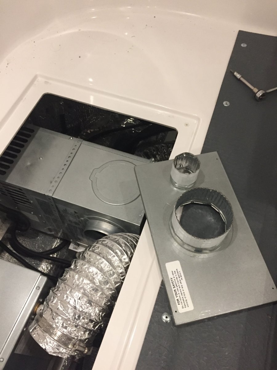
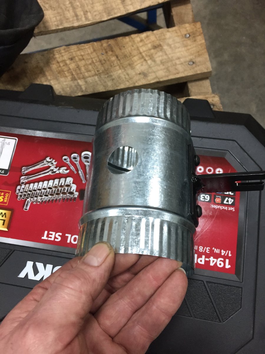
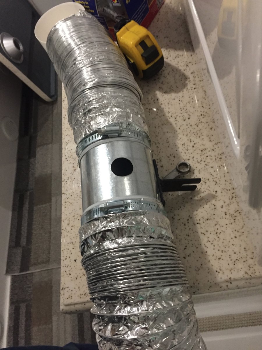
On the connection to the furnace I removed the back of the heat exchanger. There is one hard to get at screw on the bottom but the rest are easily accessible. I made two holes, a 2" and a 4" in that back plate. I could not find a 2" starter collar locally so I bought two 4" and removed the rivets on one of them and formed a two inch collar, cut to length and re-rivet.
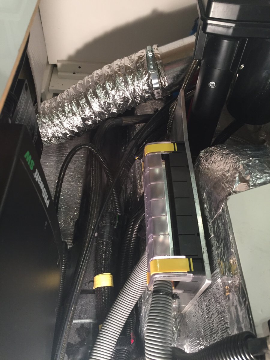
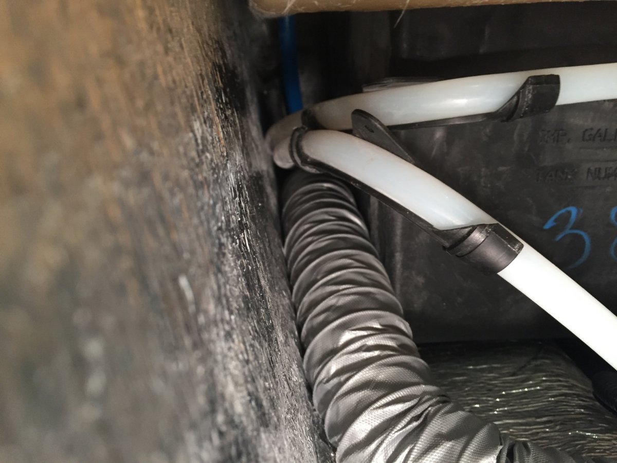
I then installed the 2" and 4" starter collars to the heat exchanger back panel and then the panel to the furnace. I then hooked up the 2" duct to the furnace. Looking in to the access hole under the street side bed you are able to see where the water lines come up and out of the trough and to the valve of the out side wash station. When the furnace fan is running it will blow out a lit Bic Lighter held in that area. So we're protecting water lines, the check valves and dumping warm air underneath the outside wash station valve.
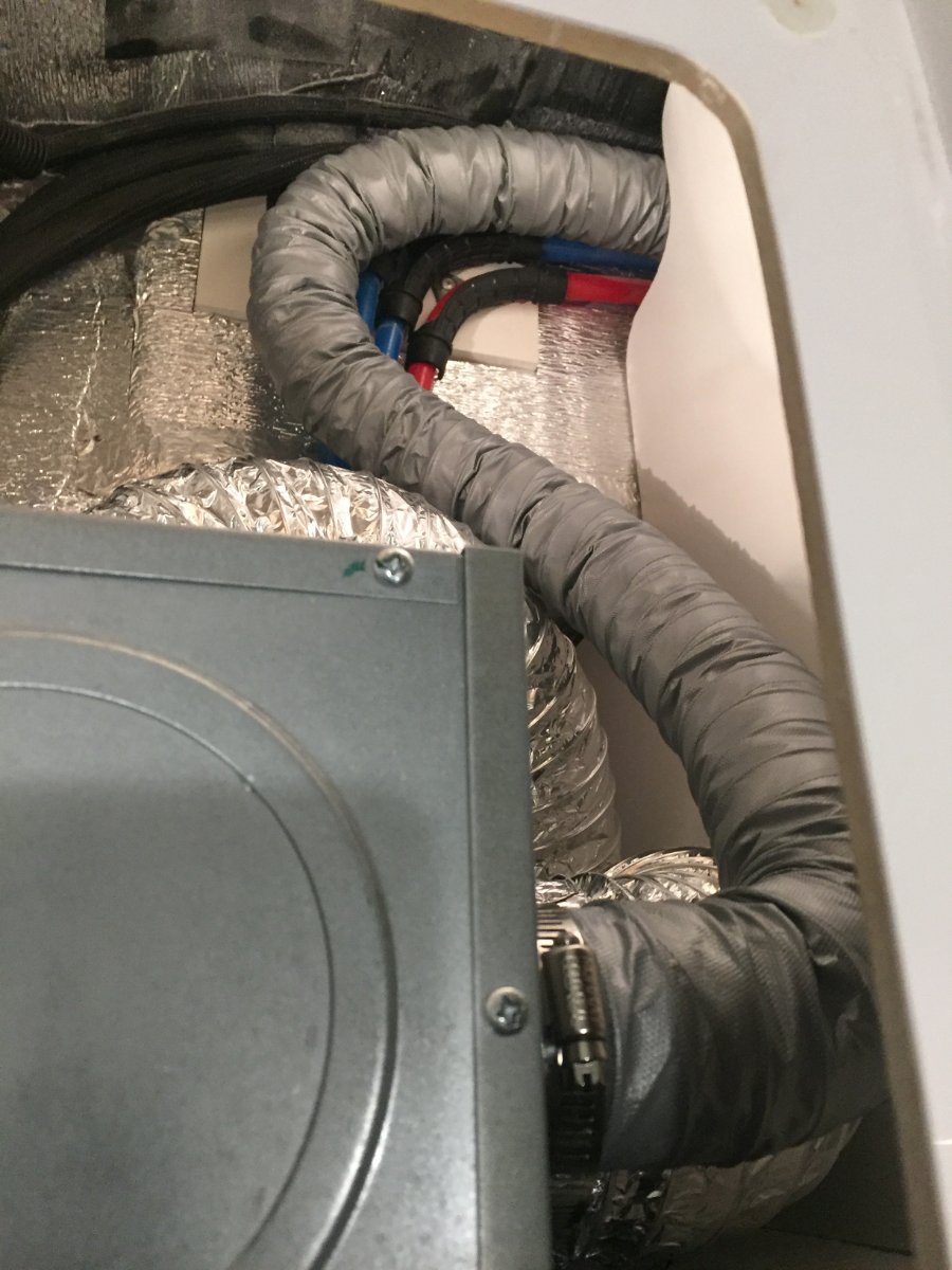
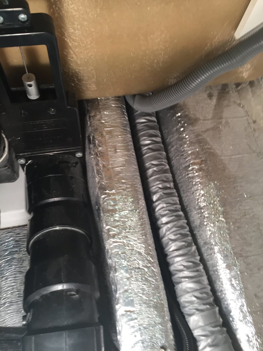
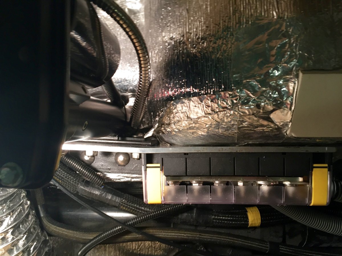
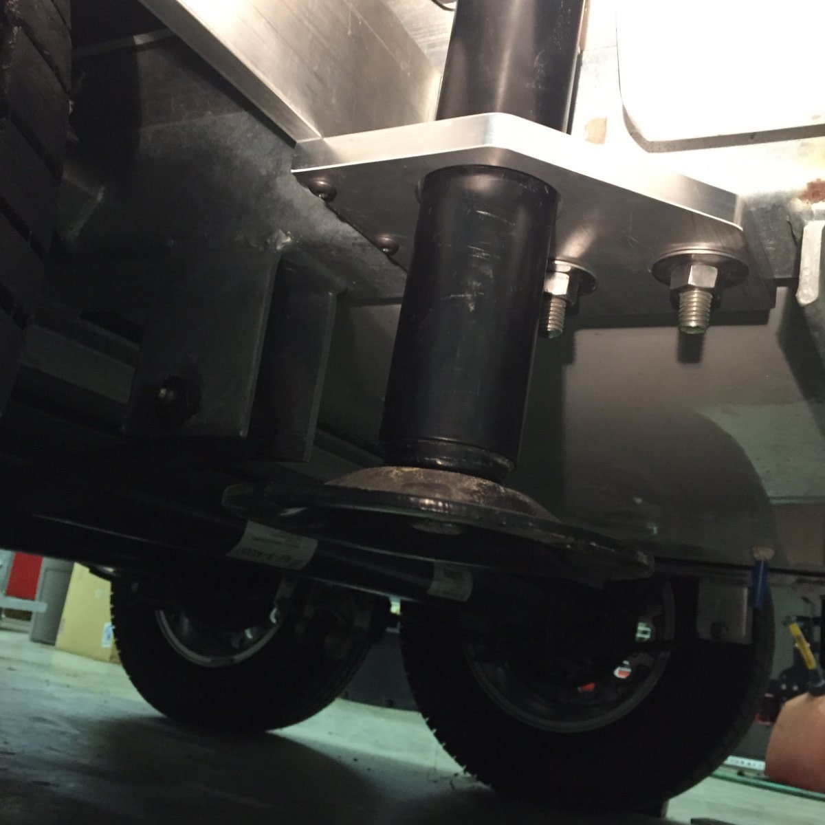
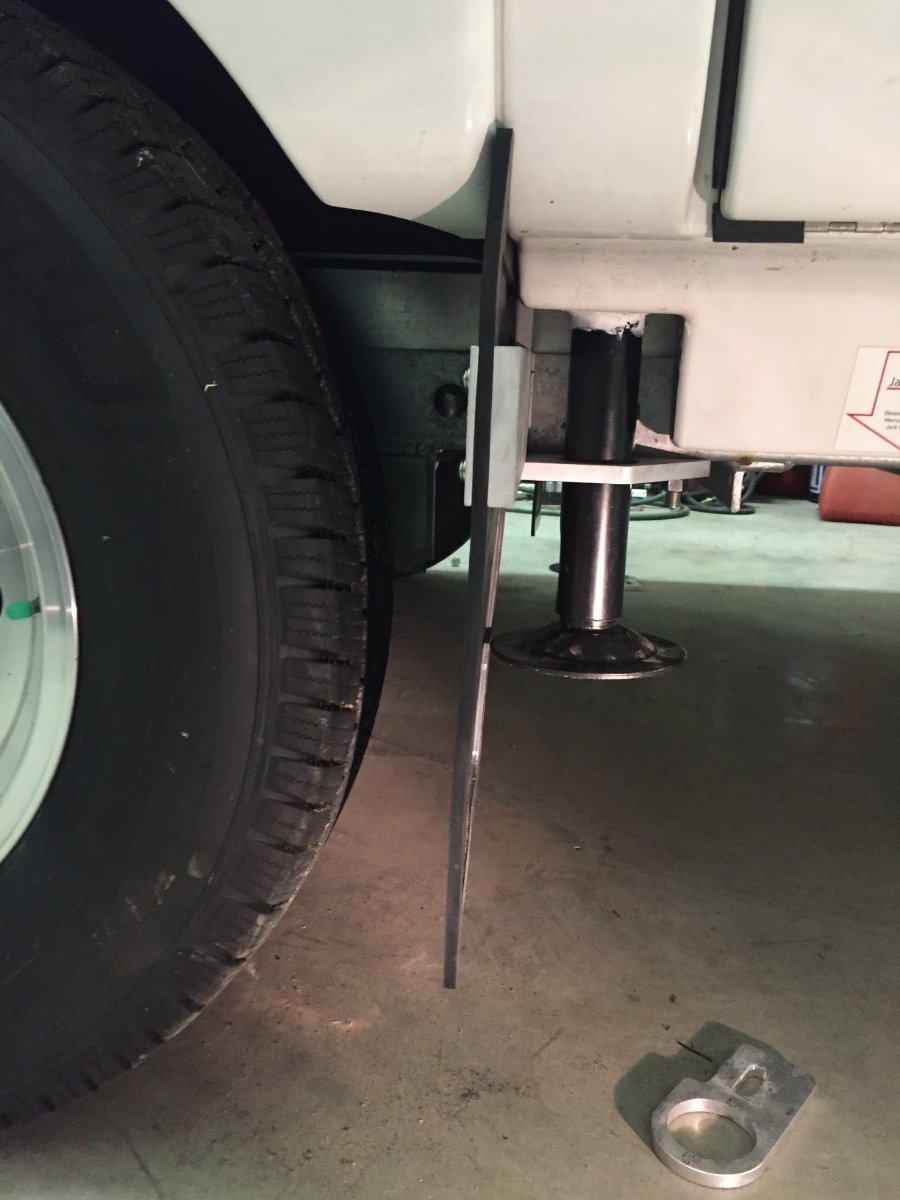
Now back at the furnace I attach a 4" heavy duty aluminum foil duct to the newly installed starter collar. It is routed forward a short distance until it can be routed across the basement to the street side and then fed between the hot and cold water lines that go to the outside wash station valve. At this point I need to use a 4" coupler that is 6" long to attach the next 8' piece of 4" duct. I use the 6" long coupler so I can add holes if I need to flood a area with heat, this particular coupler did not need to. I then routed the duct from the wash station valve along the outer wall and over the wheel well, make the corner by the battery compartment and then once getting past the wheel well go down and under battery compartment. Up in that corner I attach a adhesive base 3/4" cable anchor so I can loop a 20" releasable tie strap through it and around the 4" duct holding it up and out of the way. A second 20" tie strap is used were the duct heads down under the battery compartment, it utilizes the loop that anchors the 4/0 cable coming out of the battery compartment.
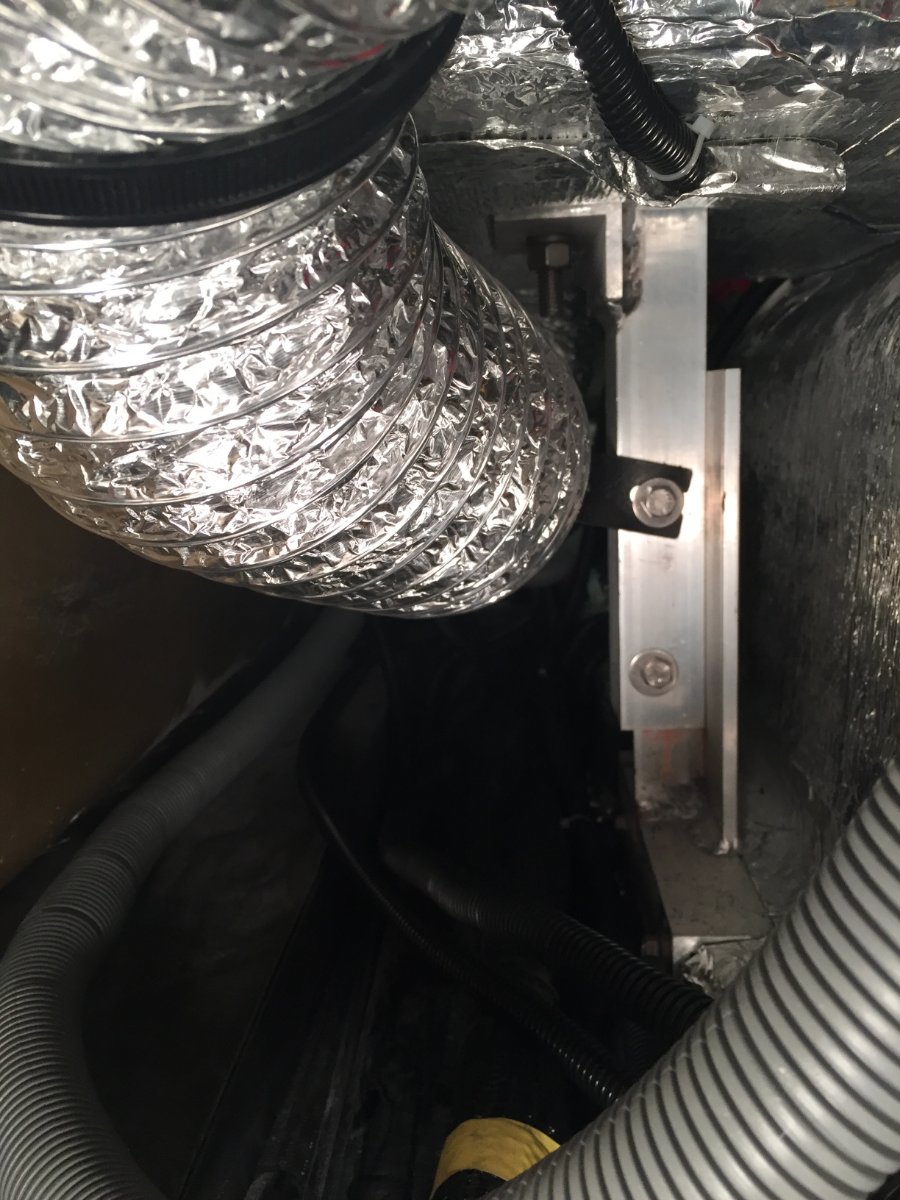
Next I prep another 6" long 4" coupler by adding a metal mounting bracket. It is bolted to the coupler using two 10-24 machine screws that go through the bracket the coupler wall and then a backing plate that has tapped holes. This coupler I will add a1" hole that will be pointed up to flood heat at the battery compartment.
The mounting bracket will be utilizing the upper bolt of the support leg for the battery compartment.
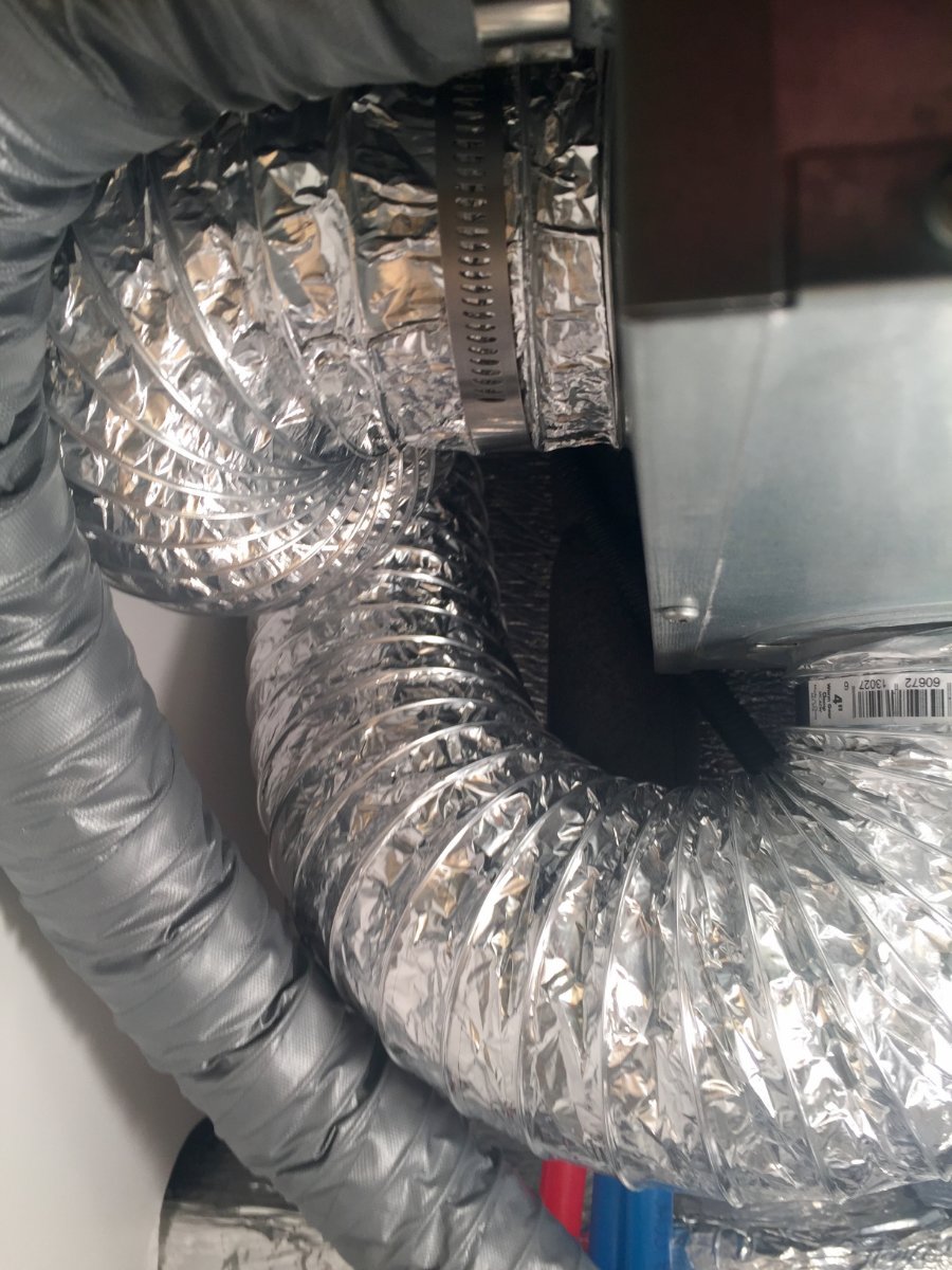
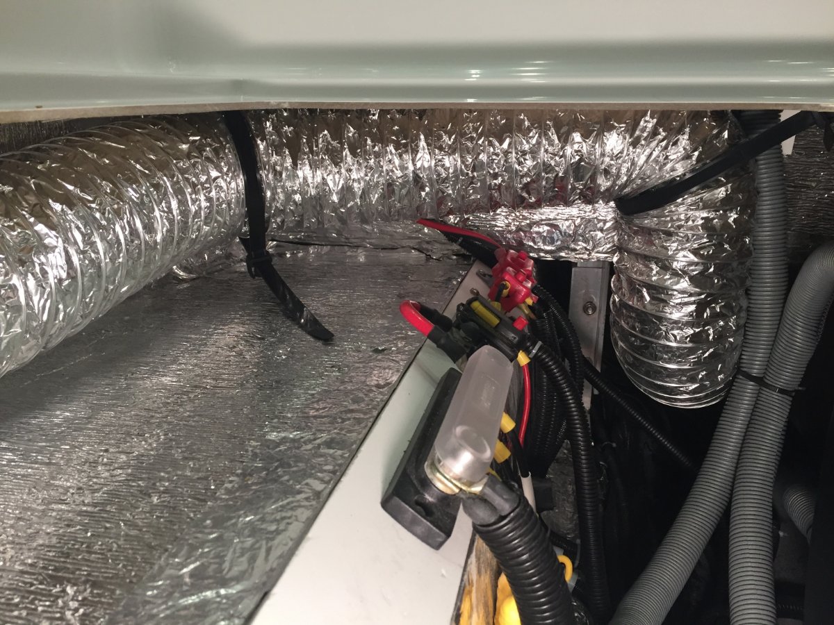
This keeps the duct up and away from the inverter and electrical components and positions it to flood heat up against the bottom of the battery compartment. The next length of 4" duct is clamped to that coupler and routed up from under the battery compartment over to and along the wheel well. It is held by two 20" tie straps similar to the other side.
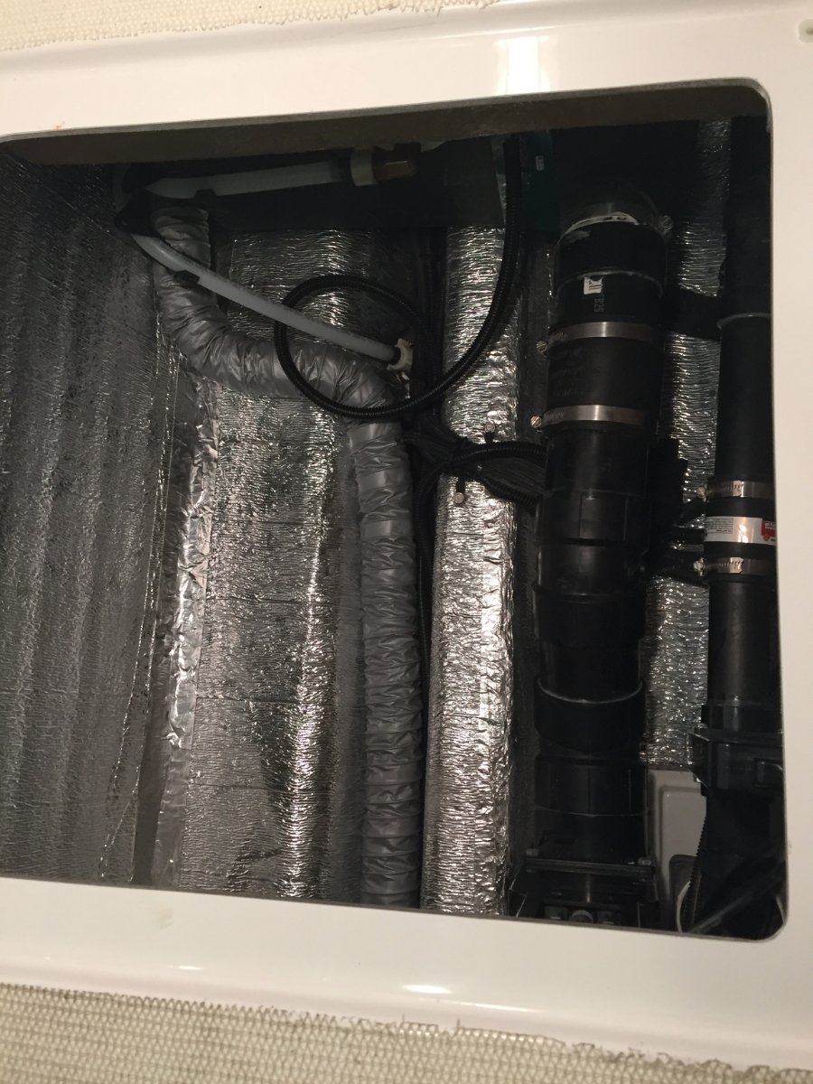
Because I want to run the heat duct under the foot space of the dinette I need to transition to 2" duct. There is access via the same trough that I utilized in the back of the trailer, but at the front there is more room and I am able to pull the 2" ducting through. From there it continues toward the front until it reaches the black tank flush inlet where it then follows that pipe back along the black tank and terminates by the water supply line for the toilet. At the transition point I add two more short pieces of 2" duct and route them down to where the main black tank drain pipe goes under the dinette foot space, they are terminated on either side of that pipe. There was not enough room to run the 2" duct but enough to force air along either side. At the transition from 4" to the three 2" ducts I simply inserted the three 2" into the end of the 4" and used aluminum foil duct tape to seal the transition. I also want to mention that I used the aluminum foil duct tape to reinforce the ends of every 4" duct by wrapping outside and inside before clamping.
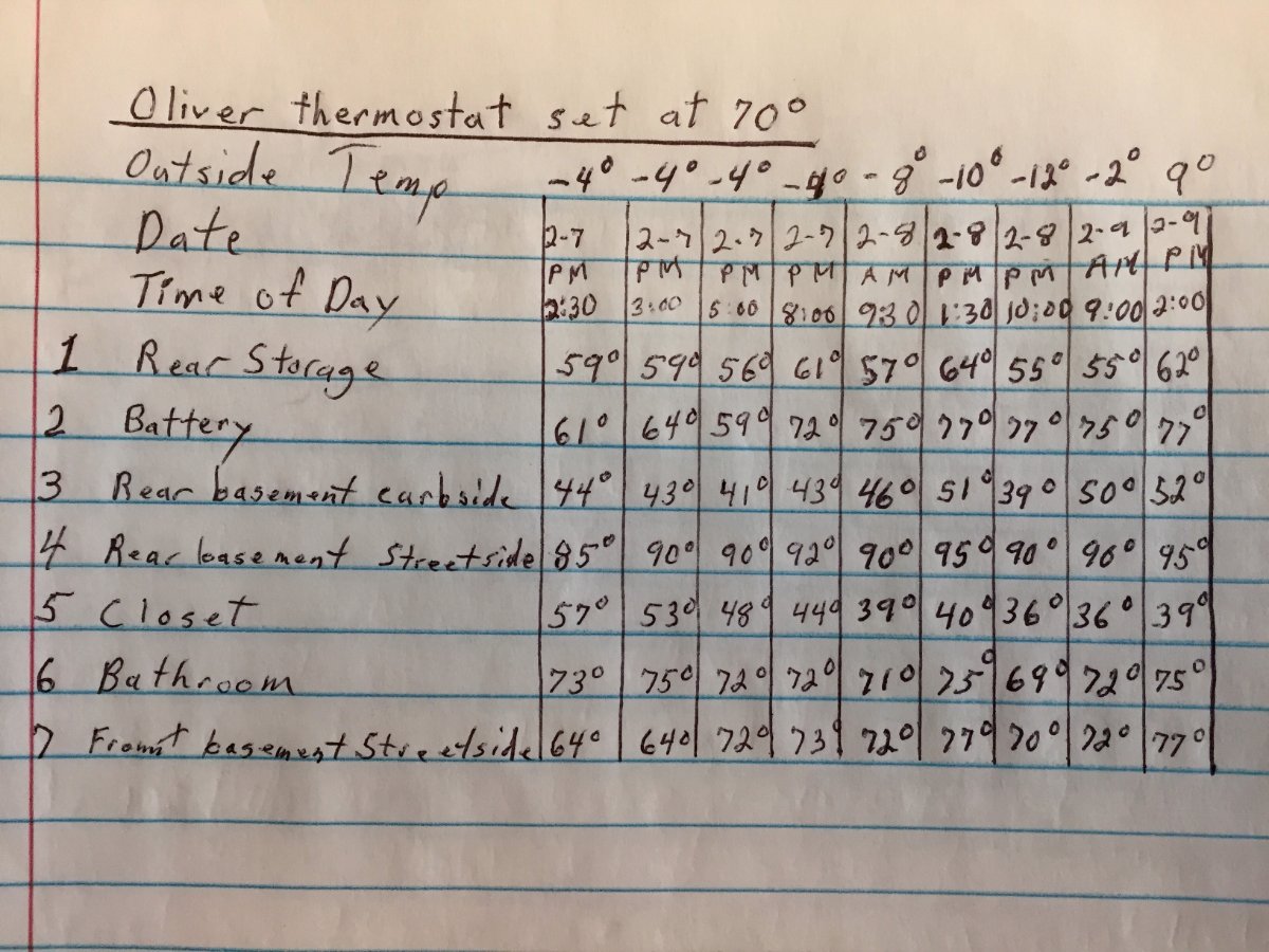
That should cover the install, now lets talk about the results of the test in subzero weather. I rounded up seven digital thermometers and put them in the areas I was concerned about.
- Was placed just inside the empty rear storage compartment.
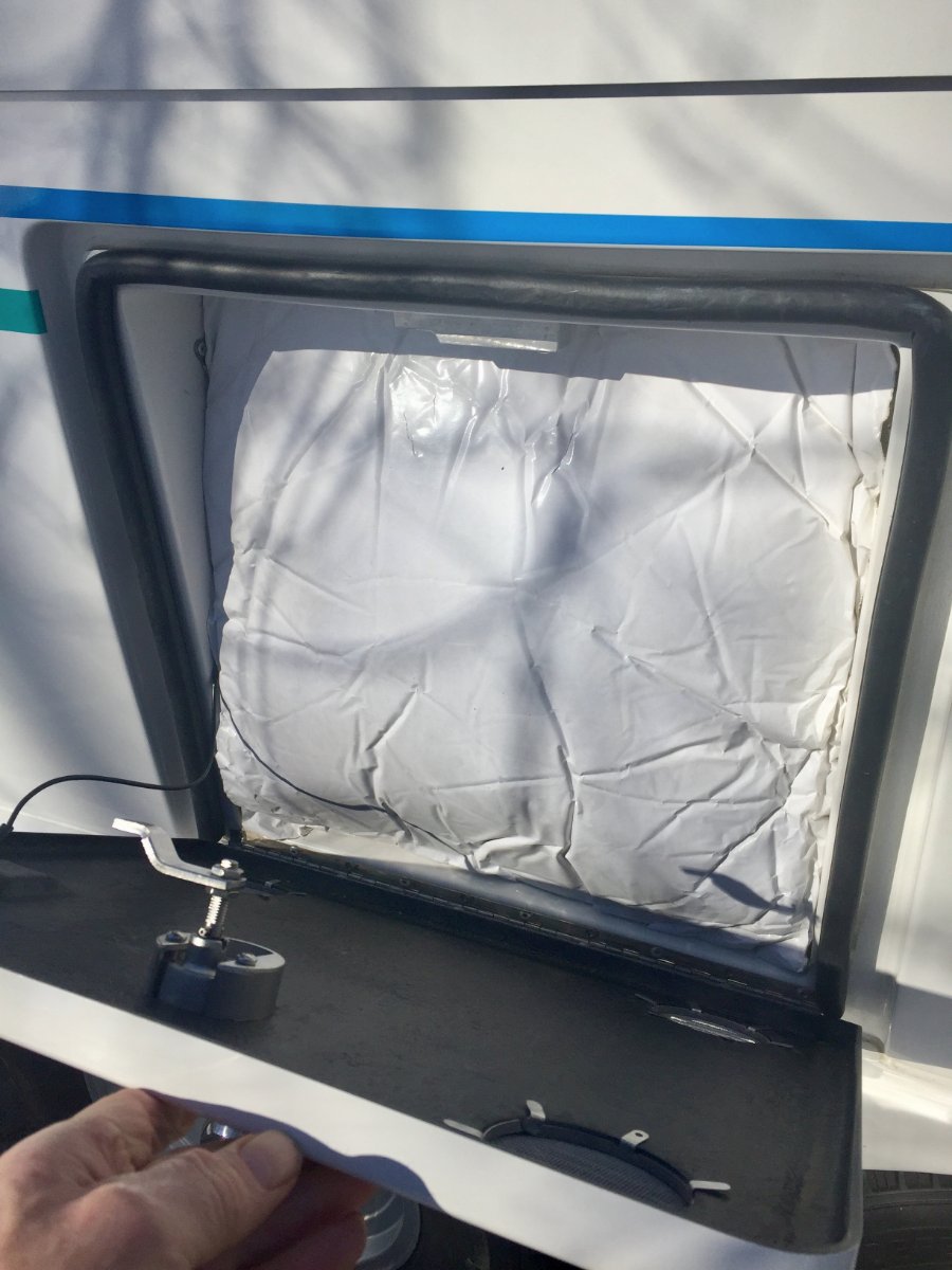
- Was placed on top of the batteries and a piece of acoustical insulation that was for large generator enclosure, it was 1-1/2" thick and 19" square. This was squeezed in the opening before the door was closed.
- Was placed in the rear basement curbside next to boondocking inlet.
- Was placed in the rear basement street side below the outside wash station valve.
- Was placed on the floor of the closet with the door left closed.
- Was placed on the lower shelf in the vanity in the bathroom with the door left closed.
- Was placed in front basement street side next to the black tank flush port line.
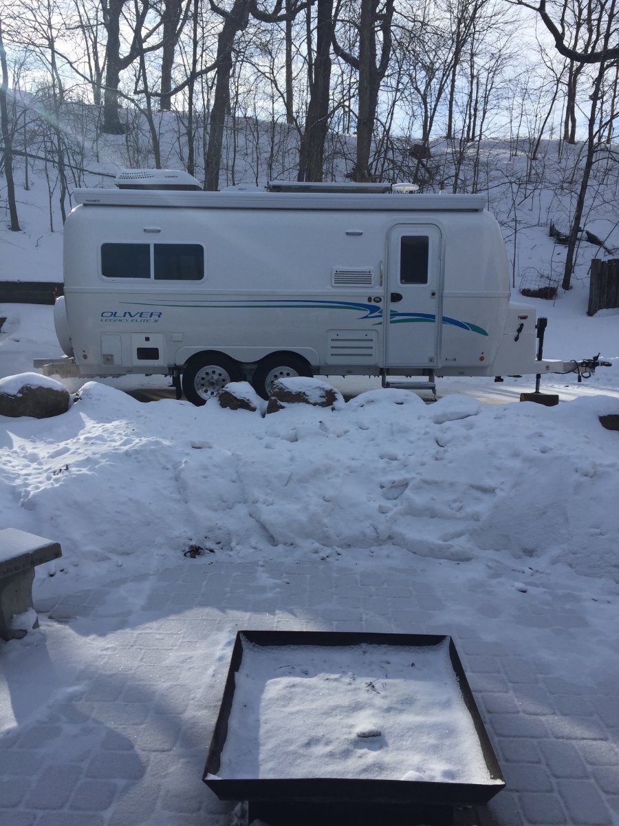
I moved it out of the heated shed at 1:00 pm on Sunday 2-7-21. I moved it back in at 3:00 pm on Tuesday 2-9-21.
The furnace was cycling off and on at -4 ' but I noticed at -8' and colder it ran continuous. I have the Truma water heater and that was also turned on. I checked propane consumption by putting on two 20 pound tanks that I had weighed and left them in place for 12 hours. It was -12' when I put them on and -2' when I took them off. Because of the subzero temperature the propane was not gasifying very well and the regulator automatically changed from the primary to the reserve after only consuming 2.353 gallons. The total consumed out of both tanks in 12 hours was 3.294 gallons, so that would be .274 gallons in one hour.
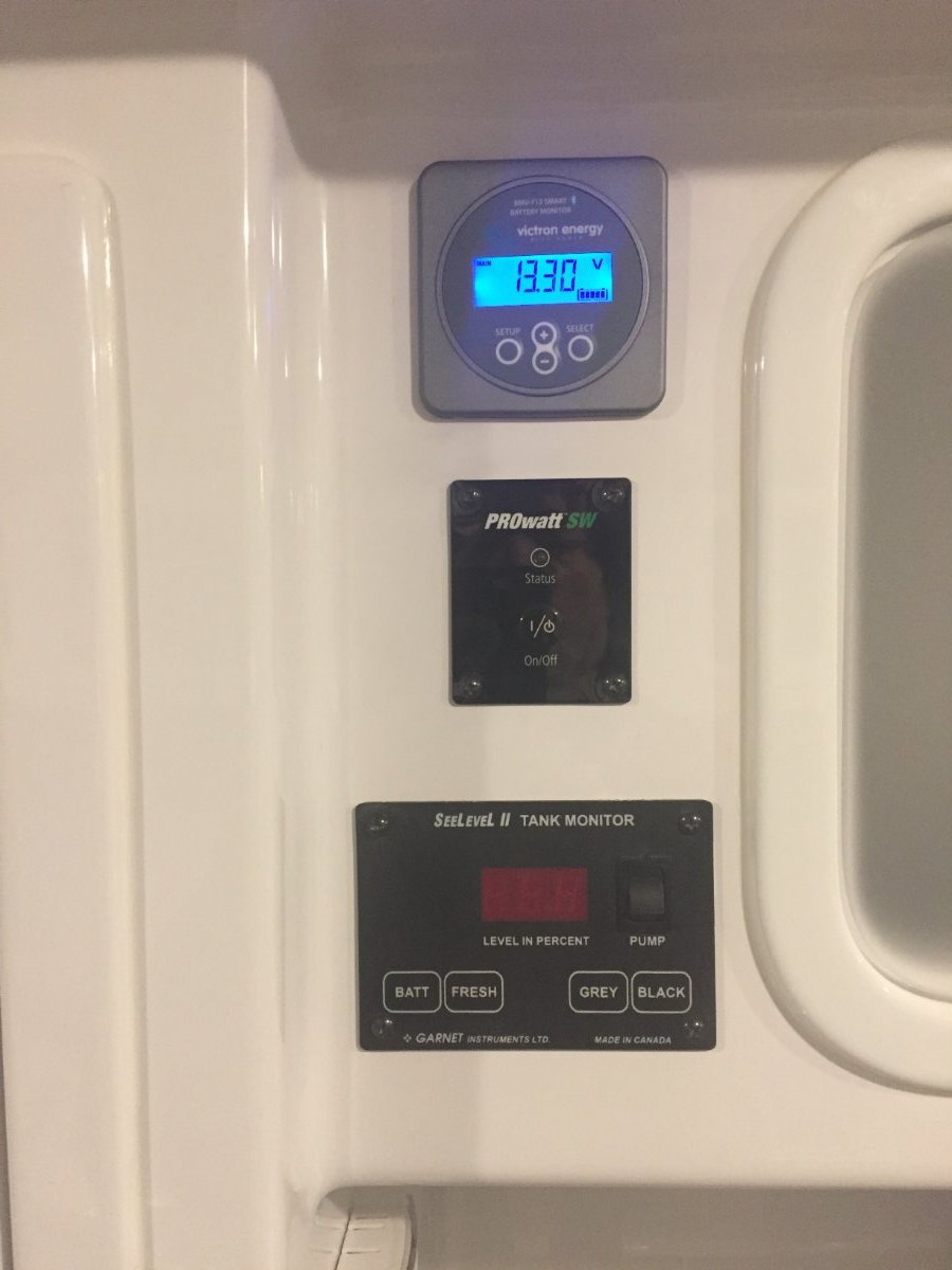
My Victron BMV-712 was telling me that I had depleted my 400 Ah Battle Born batteries to 47% and at rate of use I had two days and nine hours left.
I thought I would comment on a couple of things I like about the outcome of the project. The bathroom was comfy warm and the wall next to the bed was not icy cold.
I am not planing to take up subzero camping but it does gives me a benchmark to go off of for any situation that I might run in to. If you have any suggestions or see something that is of concern please let me know.
Paul
-
 4
4
-
17
-
 1
1
-
I believe what you have in the picture is a outlet tester. neutral ground plug.
I bought my Oliver from a previous owner but I thought he told me Oliver supplied the neutral ground plug. Maybe you can ask Oliver if that is true.
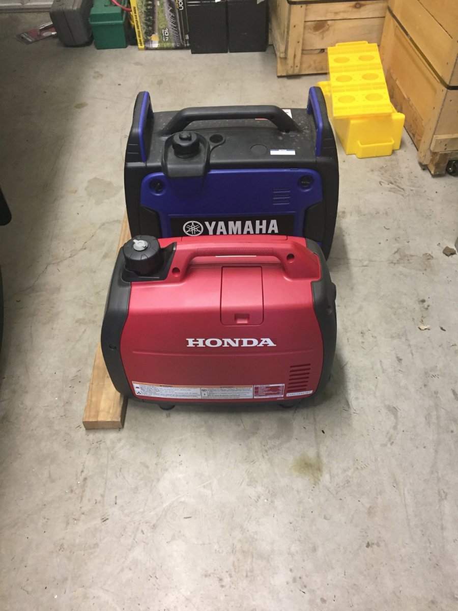
You asked if the Honda was noticeable quieter then the Yamaha. It is.
-
1
-
-
Here you go.

-
2
-
-
Good Morning
Yes it does require a neutral ground plug, with the adapter I use it is workable. I thought the fuel gauge and the lit front instrument panel were nice features also, but if it is not capable of running it's claimed max load from eco mode with out suffering a temporary low voltage it neglect's the purpose of a inverter style generator. I tried to politely tell Yamaha that in the long run they were going to lose a lot of costumers in the RV market by enticing them with the RV receptacle and then fail on performance. That is the problem when the bean counters have more input then the engineering and R&D departments in product development.
I also included pictures to show the difference in physical size.
Paul
-
1
-
-
2 hours ago, Minnesota Oli said:
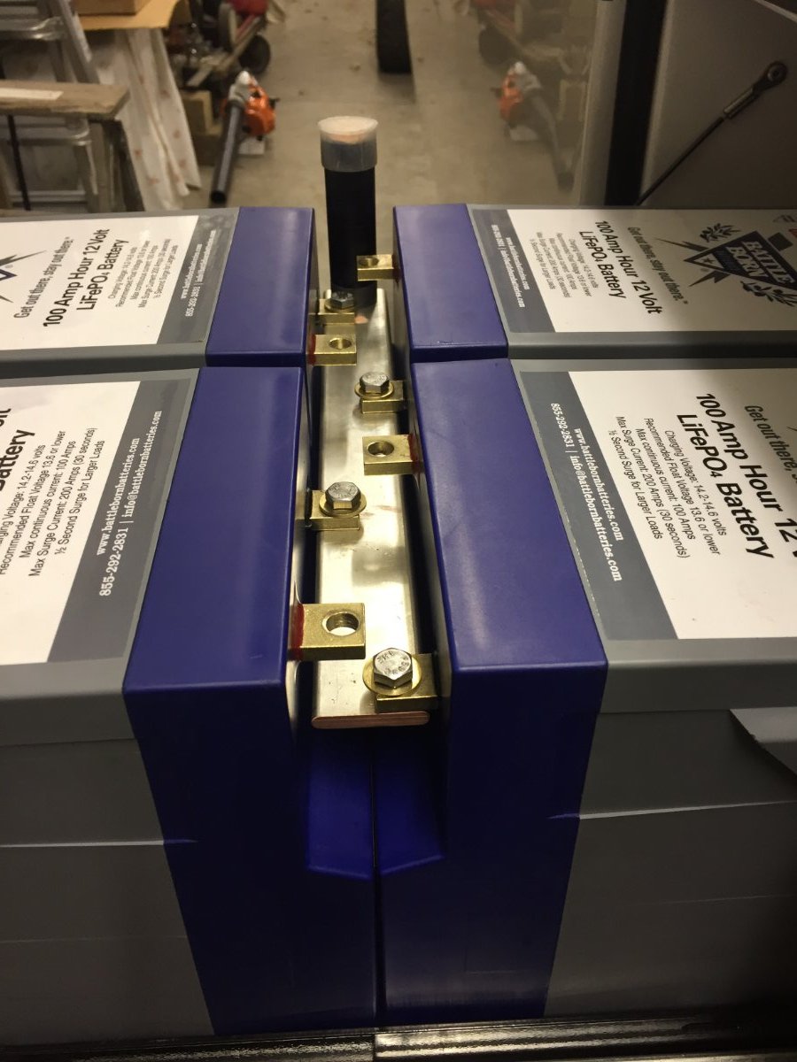
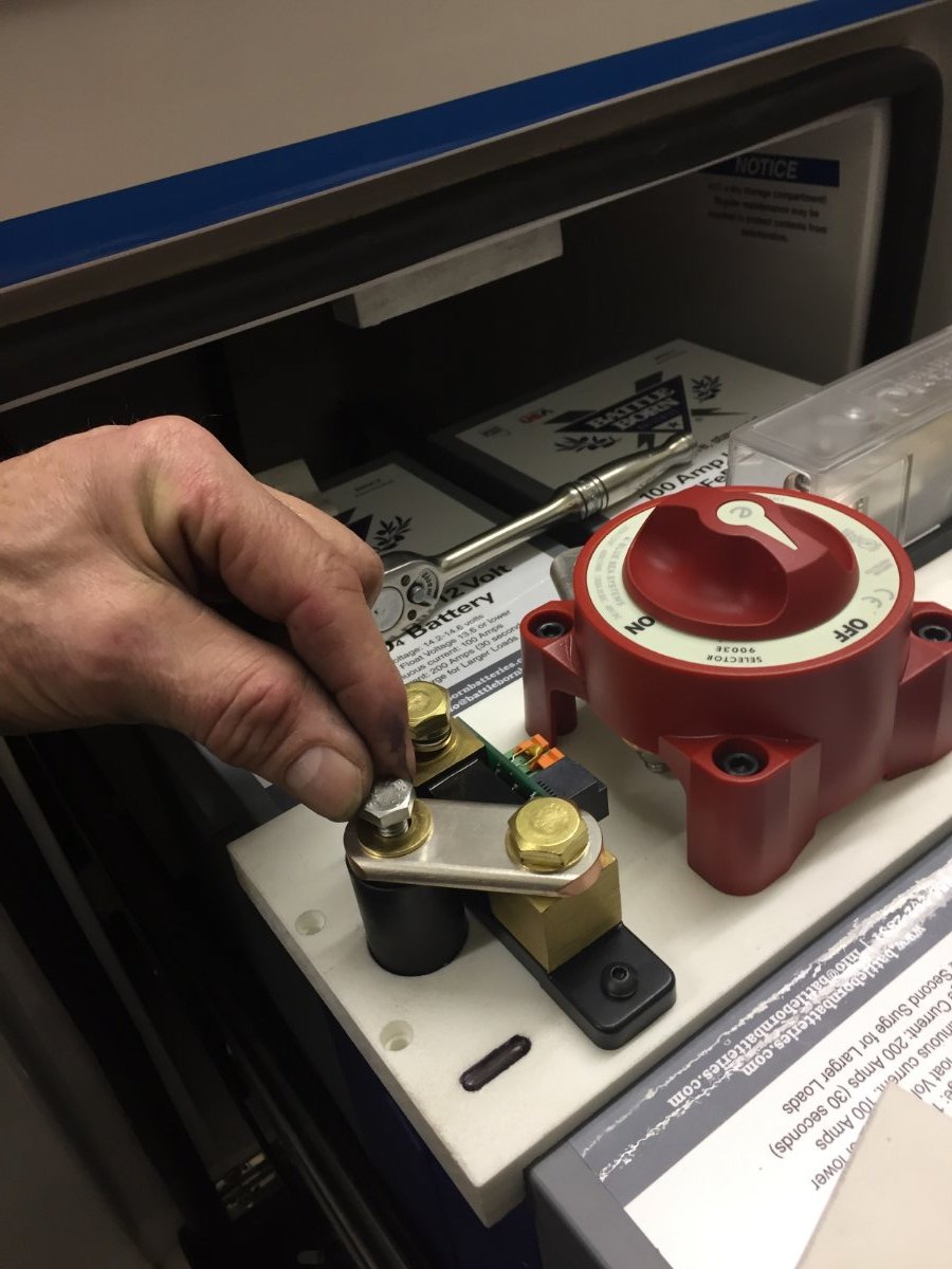
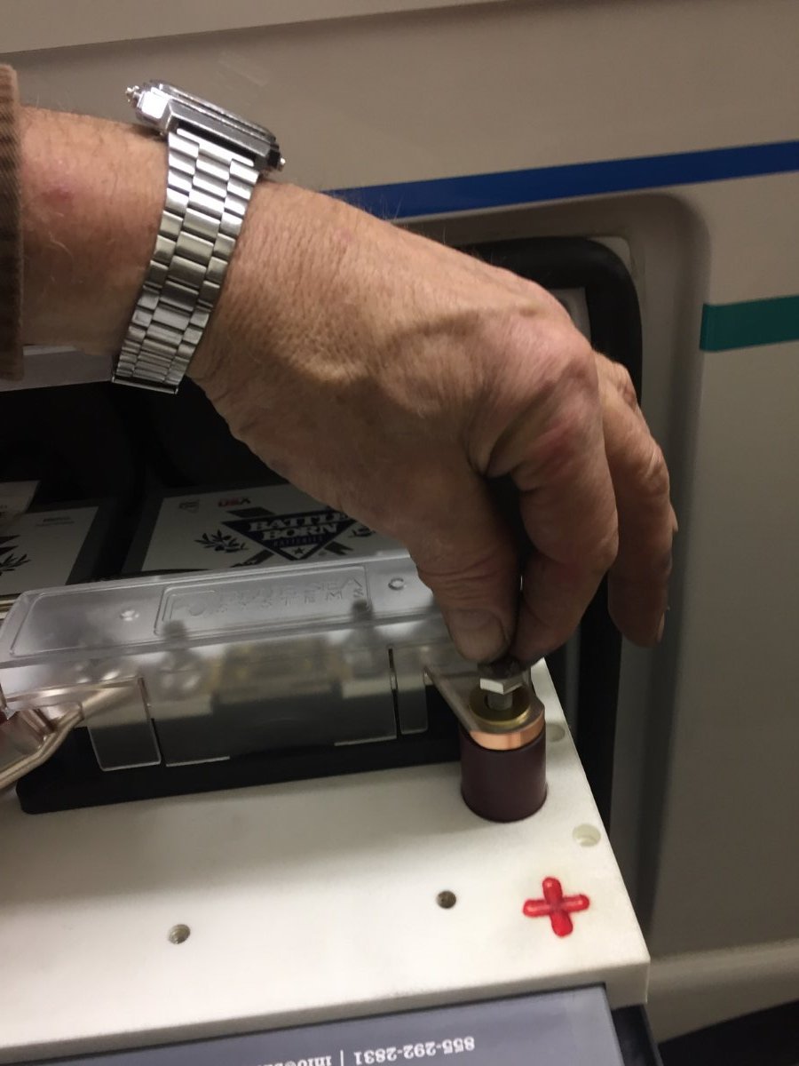
I have thought about this issue of isolating a battery from the rest in the group of four and what I would be up against. To get at the buss bar I would have to pull the star board that is mounted on top of batteries by removing two screws on each end that lock it down. Then remove the positive and negative terminal bolts and lift the star board from the batteries. Then remove the bolt of the positive terminal of the battery I want to isolate and slip a insulating material between the battery terminal and the buss bar. That should work but has not been tested yet.
The Battle Born 100Ah GC2s have their terminals laid out in such away that when side by side or facing each other the negative terminal are all aligned with each other but at a different level then the positive terminals. So I believe the were designed for a buss bar application and they do cost slightly more the the standard configuration. So I need to make a call to Battle Born and confirm this.
I was able to talk to Battle Born and was told that buss bars is there prefer or recommended method for installing multiple batteries even in a mobile application. So that was good to hear.
-
2
-
2
-
-
On 1/20/2021 at 1:24 PM, Ray and Susan Huff said:
Darn . . . . I have an email notification set up with Lowe's and Yamaha . . . . to let me know when the 2200i is again available. When I asked Yamaha, they said this Spring.
You got lucky . . . . . we've been waiting since October.
I just want to share my experience that I had with the Yamaha EF22iS 2200 watt. I bought it for the same reasons you stated but was disappointed when I found that it could not start my easy start equipped AC unless it was left in full throttle mode. My older Honda 2000 watt had no problem doing it in eco mode. I went though all channels with Yamaha and they were of no help. What I understand is the Honda has a larger horse power engine even in the 2000 watt model. So the Yamaha lacks power to get the AC started from eco mode. So I bought the Honda 2200 and it works perfectly. Hope this help you with purchase of a generator.
-
2
-
-
1 hour ago, John E Davies said:
That is very excellent from an installer’s point of view, but if it fails you are dead in the water for possibly a very long time. An installation where a failed battery can easily and quickly be removed for service, while maintaining full functionality at a reduced capacity, makes more sense to me. Several small ones connected by easily accessible cables, in other words. For an RV that gets jounced and jolted, this seems to be a prudent design. A fixed bus bar installation would be perfect for a home, but how long will it remain working in the rough world of a camper? Even if this one proves to be bullet proof, I personally would never stop worrying about it.
Battle Born batteries have no way to read onboard cell voltages and their condition, so the only way you can test one to see if it is OK is to separate it from the others, fully charge it, then do a load test with a Battery Monitor to see if it is giving you the right amount of amp hours. Repeat for the next one.. And the next one.... until you find the bad one. If BB wil update their onboard BMS to allow individual cell monitoring, a solid bus installation will be more practical, but still fairly vulnerable to shaking damage. Which IMHO would NOT be covered by their excellent 10 year warranty. “This warranty does not cover negligence or misuse of the battery. If it is deemed that the battery was used improperly, you will be subject to a $150 an hour repair charge plus parts and shipping.”
John Davies
Spokane WA
I have thought about this issue of isolating a battery from the rest in the group of four and what I would be up against. To get at the buss bar I would have to pull the star board that is mounted on top of batteries by removing two screws on each end that lock it down. Then remove the positive and negative terminal bolts and lift the star board from the batteries. Then remove the bolt of the positive terminal of the battery I want to isolate and slip a insulating material between the battery terminal and the buss bar. That should work but has not been tested yet.
The Battle Born 100Ah GC2s have their terminals laid out in such away that when side by side or facing each other the negative terminal are all aligned with each other but at a different level then the positive terminals. So I believe the were designed for a buss bar application and they do cost slightly more the the standard configuration. So I need to make a call to Battle Born and confirm this.
-
1
-
-
Hey John
You know I neglected to question him about that, I had so many thoughts and question at the time of the call I failed to follow up on it. I had given brand and model info so he could check for capability and that is when he told my to unhook temp probe at the back of the Zamp control. He was also aware of the setting on the Progressive Dynamics charger board that needed to be changed.
Paul
-
Hi John
I have all the stock charge controllers, the Zamp ZS-30A solar charger does have as selectable battery type on the display panel with LiFePO4 as a option. Battle Born did advised me to disconnect the temperature probe from the Zamp solar controller. The Progressive Dynamics Power Center charger has a selectable jumper on the board that needs to be put LiFePO4.
Paul
-
1
-
-
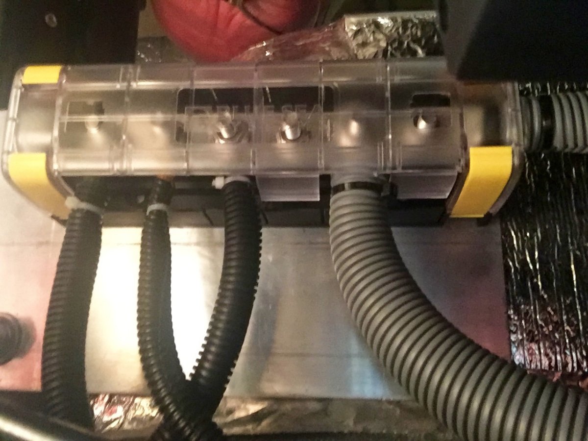
https://www.bluesea.com/products/2718/MaxiBus_Insulating_Cover_for_PN_2105_and_2126https://www.bluesea.com/products/2126/MaxiBus_250A_BusBar_-_Six_5_16in-18_Studshttps://www.amazon.com/Battery-Spartan-Power-Negative-Terminals/dp/B07MXQSNHR/ref=sr_1_5?dchild=1&hvadid=77859219137661&hvbmt=bb&hvdev=c&hvqmt=b&keywords=spartan%2Bcable&qid=1612200841&sr=8-5&tag=mh0b-20&th=1
On 1/28/2021 at 12:34 PM, BackofBeyond said:Yep - or at a minimum - design sheet, specs, etc.
A really nice job. One I will have in mind in a few years.
RB
Well I want to try to answer to this request. Its a project that requires you to cover a lot of ground so I decided to break it down to individual aspect of the project.
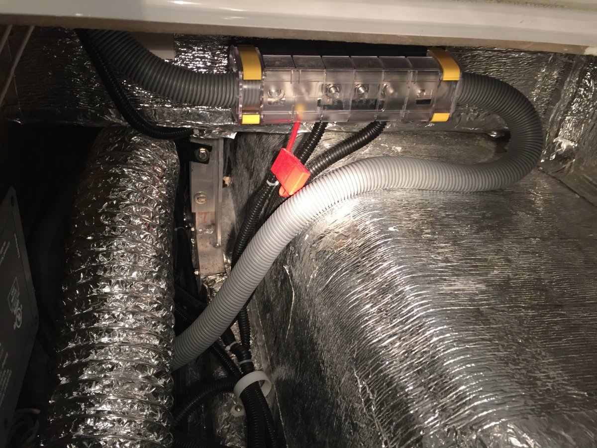
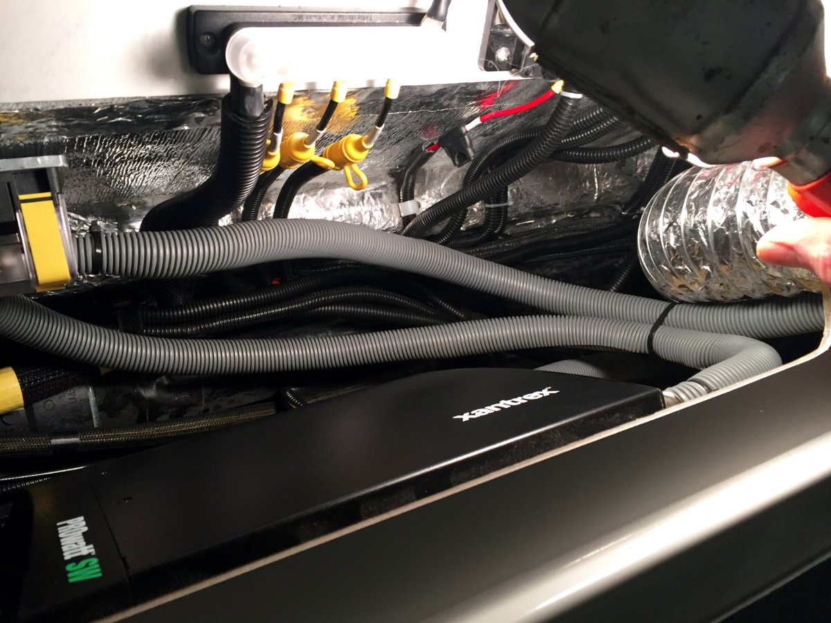
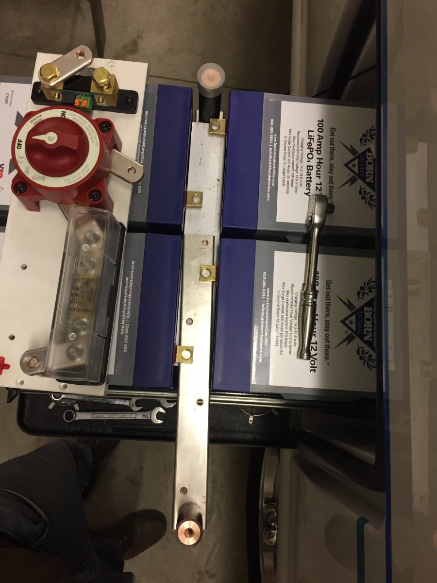
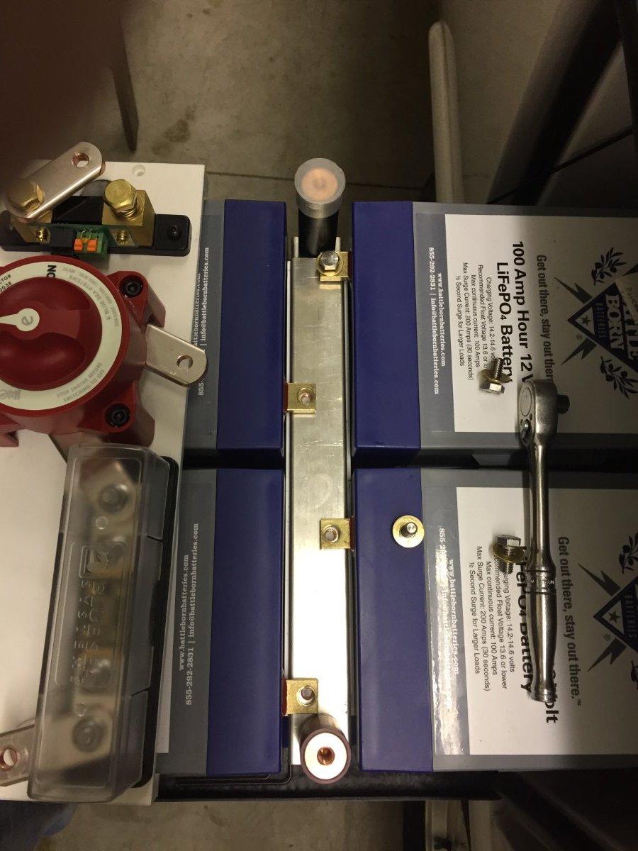
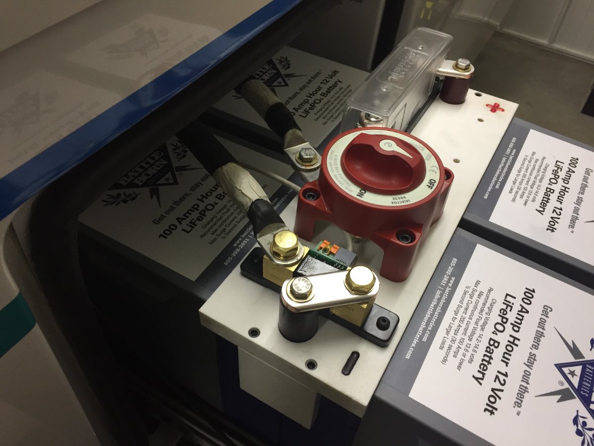
So I am standing at the side of the Oliver looking at the open battery compartment. I see this maze of cables and I am thinking of a discussion on the Oliver Forum. It was suggesting that there could be a improvement to this maze of cables by installing bus bars, one positive and one negative inside the basement of the Oliver. This would allow the cables from the various components such as Zamp Solar Controller, Side wall solar Port, Progressive Dynamics Power Center, and the chassis ground to be routed to the relevant bus bar. With that done it would only leave the positive and the negative 4/0 cables leading to to the battery compartment from each perspective bus bar. With that said the only other cables that my set up has is the one that leads from the Victron BMV-712 battery monitor to the remote display. I also have a now unused wire that was for the temperature probe that was hook up to the Zamp solar controller. The service person at Battle Born advised to disconnect this at the Zamp solar controller, I did leave the unhooked wire in place for possible future use.
I then went inside to determine the placement of the bus bars considering the number and lengths of cables that need to be relocated and how I was going to attach them in the Oliver basement. I was looking at the positive 4/0 cable coming in to the basement from the battery compartment then going to the main fuse block and then continuing on to the inverter. That is when I thought about swapping out the fuse block with the positive bus bar sense the 4/0 cable is already run and no need to make up positive 4/0 cables. It also had a mounting block already in place. This meant I could move the main fuse out to the battery compartment next to the positive battery post to better protect the wiring. This was another topic I remember following on the Oliver Forum, so much information to be had.
I looked at how the various cables were run into both sides of the battery compartment and they had positive on one side and negative on the other. So it made sense with the wire lengths the way they were to try to find a spot to mount the negative bus bar in the compartment under the street side bed.
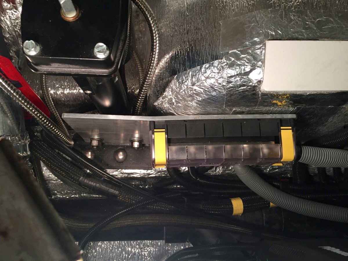
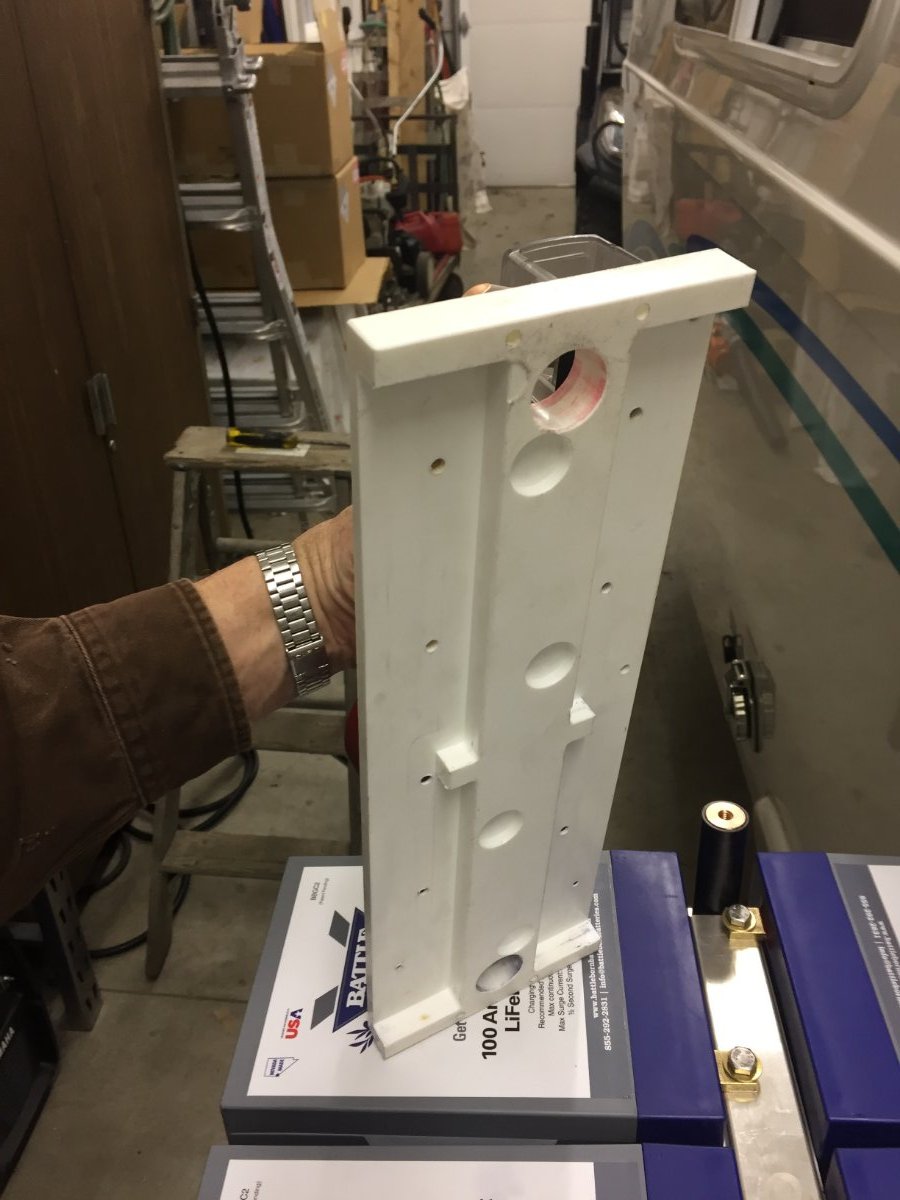
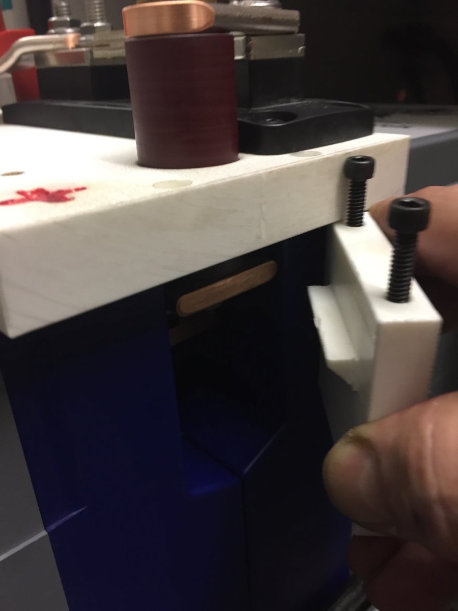
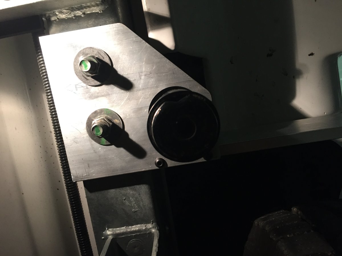
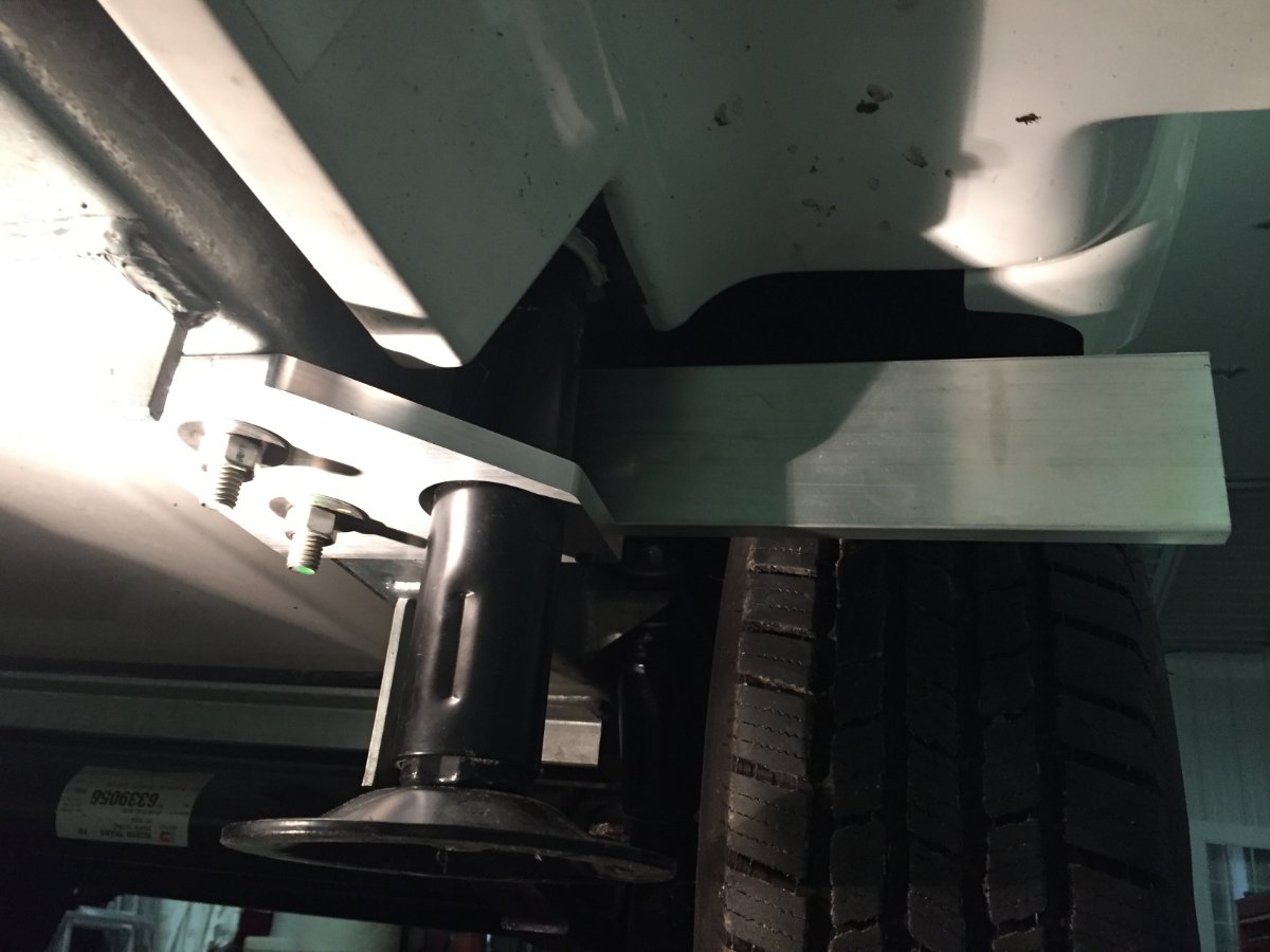
I started looking for a place or a way to do it with out having to glue a block to the fiberglass. I noticed two 1/2" bolts that were used to mount the street side stabilizer to the frame. I used a 1/4" aluminum flat that was 6" X 14" long. I then drilled holes to match the stabilizer mount. I then had to put a slight bend about 5" from the end so the plate would run parallel to the wheel well. That is where I mounted the negative bus bar. When I pulled the cables back out of the battery compartment I was able to do it with out removing the terminal ends. Some I had to bend slightly to get them through the cable glands, but this saved me from having to mess around with installing new ones. All the wires turned out to be the right length except the positive wire from the remote solar port. I was able to shorten that wire where there was a inline fuse and add a ring terminal. The negative 4/0 cable that went from the battery to the inverter was then rerouted to the negative bus bar. The only cable I had to buy was a three foot 4/0 to go from the negative bus bar to the inverter.
-
1
-
1
-
-
One possibility are the panels clean? You could try shore power to see if the battery is capable of hitting full that would eliminate the battery as the problem.
-
1
-
-
On 1/28/2021 at 12:15 AM, John E Davies said:
That is gorgeous, can you tell me how you did it? I have seen a similar one but it was welded up from four pieces of 1/2” plate. I am guessing you have a background in metal fabrication? You just can’t find a heavy wall aluminum receiver extrusion with the correct inside dimensions for a regular 2” ball mount or bike rack. I am sure that is why Oliver makes their own 1.5” receivers “in house”.
I am really blown away, I have to complement you on your skills. I would like to shake your hand. 😬 The only thing that would bother me would be ramming that pretty part into a boulder while backing into a campsite.
I found the material..... https://alcobrametals.com/product/3-6061-t6-extruded-square-bar/ .... I wonder what a machine shop would charge to remove all that inside metal....?
Thanks,
John Davies
Spokane WA
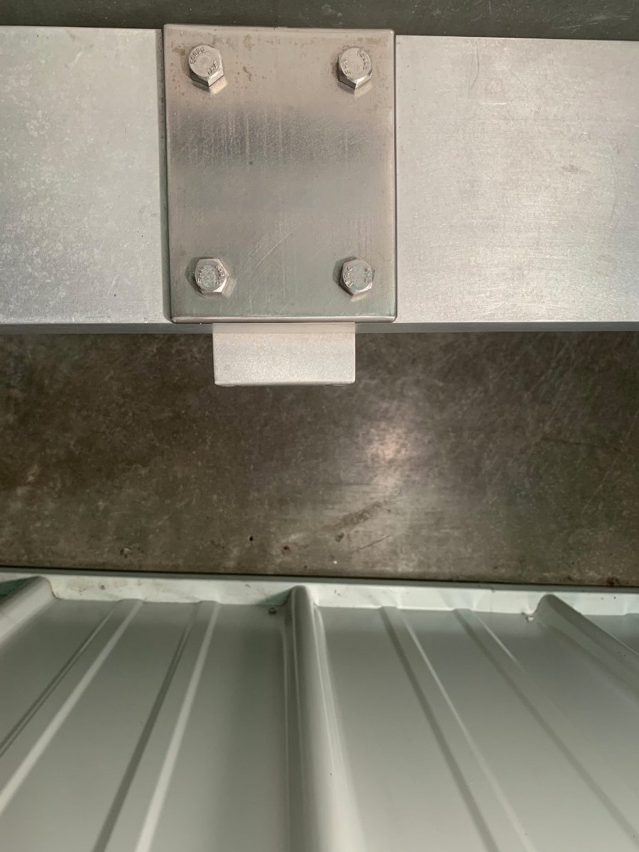
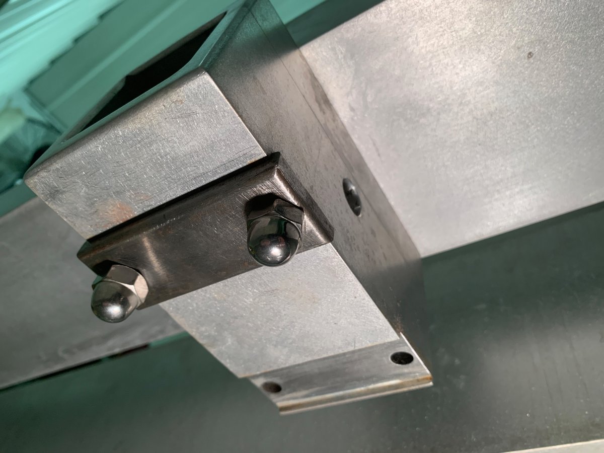
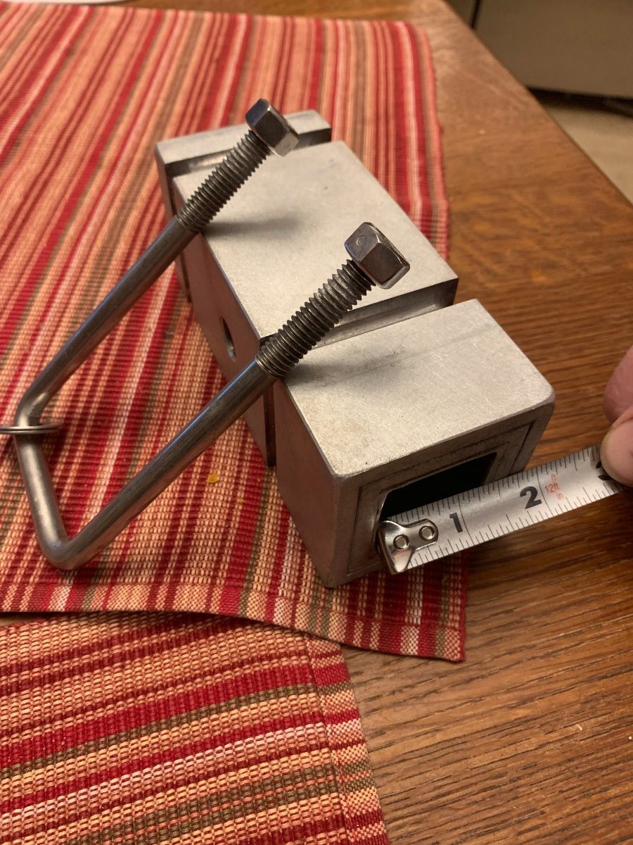
I misspoke that it came out of a solid piece. Here are some pics to look at. I used what I had on hand. It was one piece that was 3 '' by 2'' and cut a 2 '' wide by 1 1/2 '' deep slot down the length of it. The other was 3 '' x 1 '' and cut a 2 '' wide by 1/2 '' deep slot down the length of it. I used a quantity of four 1/4 - 20 '' stainless steel socket head cap screw to fasten together. Then drilled four 3/8 '' hole through side wall, two per side to match the existing holes that were in the factory cross member. I reinforced the mount with stainless steel plate top and bottom because of the 3/8 '' through holes in the 1/2 '' wall of receiver.
-
1
-
2
-
-
Thanks John
I really appreciate the complement especially from you.
I also appreciate the reminder of the use of safe practices around potentially dangerous areas. Especially when putting up pictures that the rest of the Oliver commuity will see, a person needs to show good example.
Thanks again Paul
-
1
-
-
20 hours ago, Overland said:
That's a very nice install. I love it.
How are you strapping down the batteries so that they aren't going to move separately? I was using ratchet straps on mine, but even so they seem to move around quite a bit, judging by the marks on the cases. That would be my biggest worry with using bus bars. I don't know the internal construction of that specific model; but on their standard ones, I think there's definitely a possibility of damaging them by stressing the terminals. (Or you might lose your warranty if the seal around the terminals gets cracked.) I'm sure you've considered all of that, but I'd be interested to hear your thoughts. Worst case, with the terminals being on the same side on those particular batteries, would be that they start to move enough that the bus bars contact - but I guess that strip of PVC between them would make me feel more comfortable? I don't know - I'm still a bit hesitant despite seeing your install.
Despite that hesitancy, I'm impressed. It's so much cleaner than having big cables running everywhere.
Maybe VHB tape between the batteries? That might be strong enough to make them move as a unit.
What are you using for the terminals/risers at the ends of your bus bars? I assume that's something custom that you made?
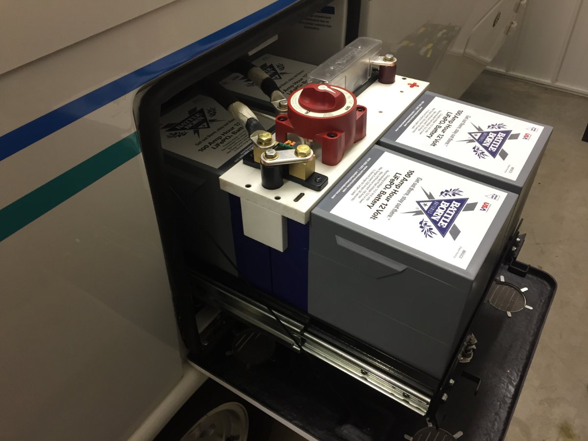
If you notice the under side of the star board I have cut relief so when it is slid down over the pos and neg posts it also locks the four batteries in place. It truly feels like one large battery,they do not even wiggle. Then the tray does the rest. I will be watching for damage by the strap hooks but it truly acts as one big battery so I hoping it is not going to be a problem.
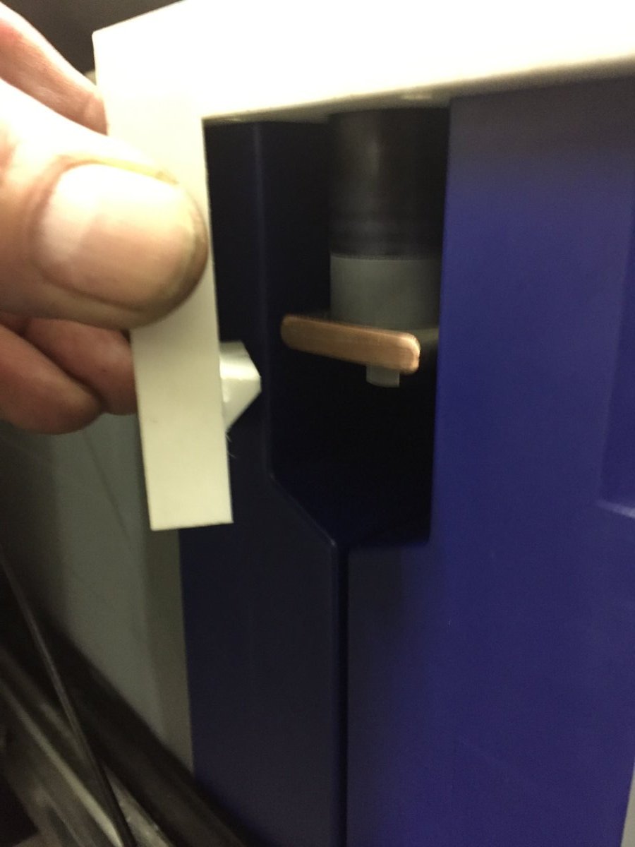
The neg and pos terminal posts are made from 7/8 round copper with a pvc sleave pressed over the OD.
-
1
-
-
1 hour ago, John E Davies said:
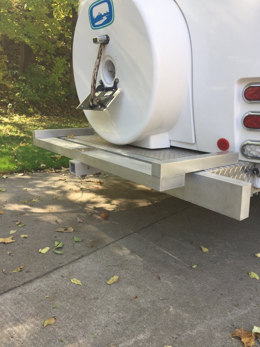
That is very slick. Is the 2” receiver aluminum? If so, can you share a link? is it this reducer? .....https://www.fayettedistribution.com/Andersen-2-1-2-to-2-Aluminum-Hitch-Reducer-p/3800.htm
It is REALLY hard to locate a 2” bolt on receiver that isn’t steel. I would like to see a closeup of how it is attached please. I can’t figure out how you did it....
Do you have a pic of the unaltered Ollie hitch? I haven’t actually seen one. Does the receiver still clear the ground when going over a dip? It looks as if the crossmember underneath would drag first.
Thanks,
John Davies
Spokane WA
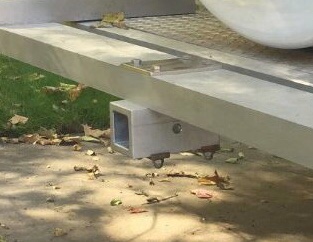
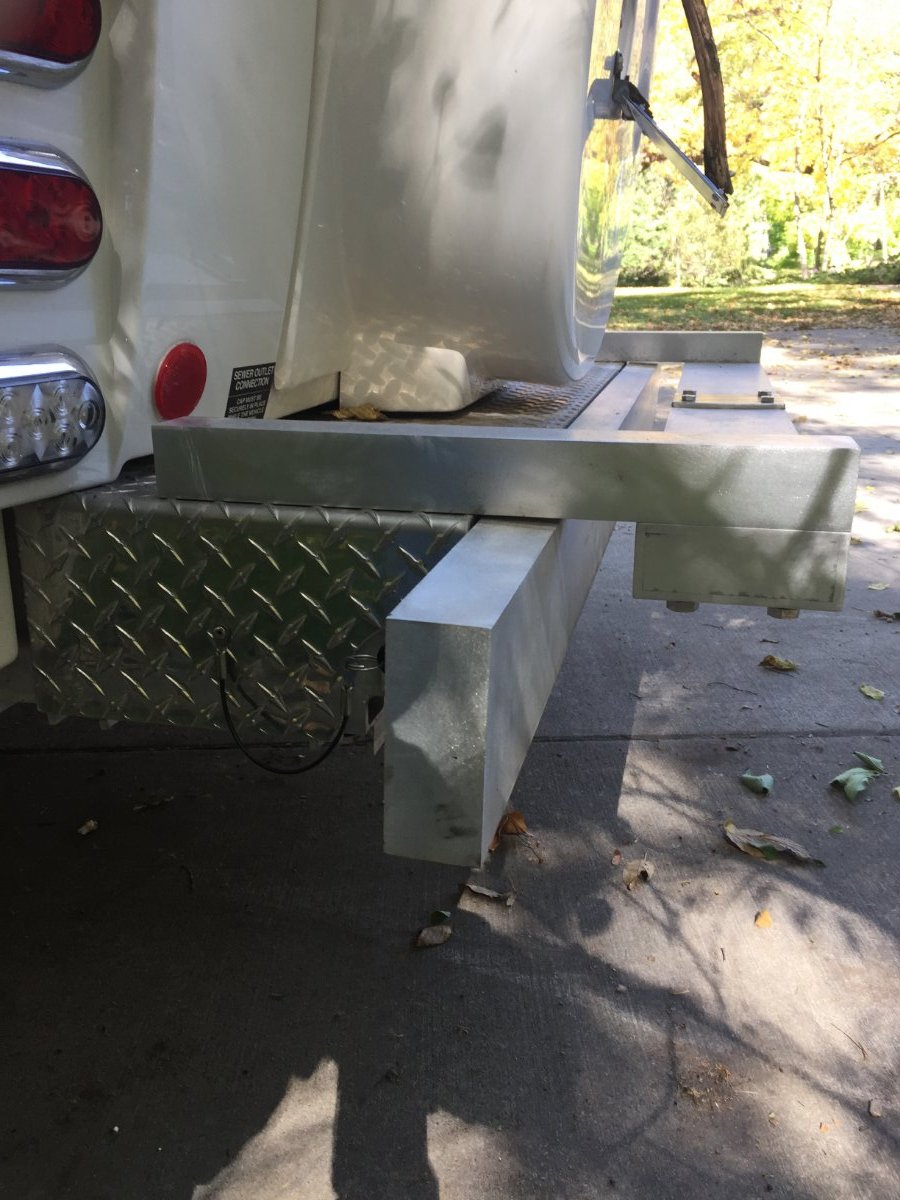
Hi John - This receiver is aluminum and I fabricated it out of a solid piece. I wanted something that would mate up to the cross member that already had 4 holes drilled for the factory 1-1/4 inch receiver. So, my receiver has holes drilled through the length of the wall and I added 2 stainless steel plates at the bottom and top which the bolts are threaded into.
The receiver sits at 17 inches and the cross member of the trailer is at about 14 inches, so plenty of room.
Unfortunately I don't have a picture of the old hitch. It consisted of 2 pieces of aluminum square tubing, 1 sliding inside the other with pins to secure. Now the 2 inch solid takes the place of them. The cross member was mounted on top which hampered you from pulling the spare tire cover off, so you had to remove the pins and pull the hitch before you could get to it. These were difficult because they would bind when pulling the hitch off. I mounted the cross member below the 2 inch so now no interference getting the spare cover off. The only negative is when you flip open the door to access the sewage pipes you have a little bit less room to reach in, but very do-able.
-
1
-
3
-
-
1 hour ago, mossemi said:
Excellent!
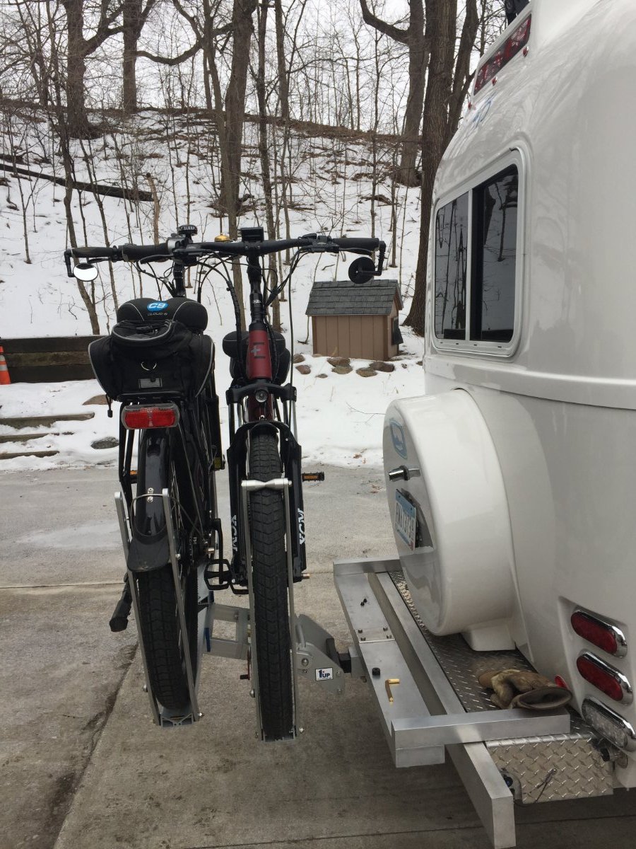
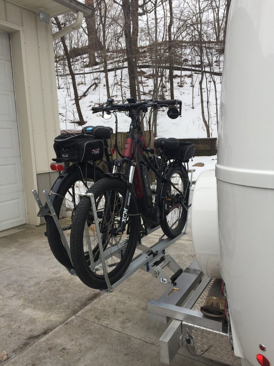
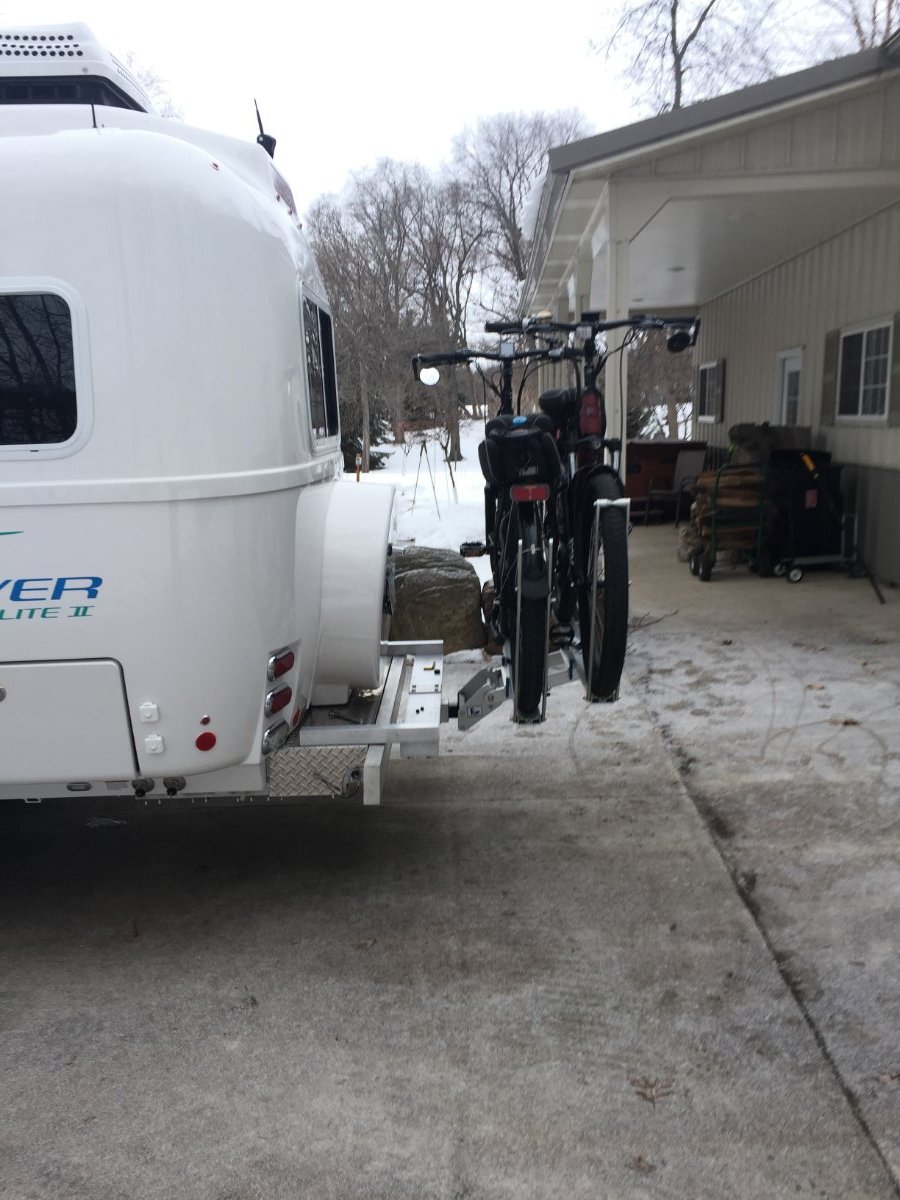
Just wait until Ray and Susan see your 1UP rack and mount.
Mossey
We love our 1UP. My kid loves their rack for their ebike as well.
-
1 hour ago, mountainoliver said:
That looks great! Are the two aluminum bars that mount the frame solid 2x2?
Hey Ken, yes it is! This allows me to drill and tap the pieces. I used 1/2 in stainless steel bolts going through the frame and up into the 2X2. The cross member is from the existing receiver hitch. I pulled the plugs on the ends and inserted a solid piece of aluminum. I then bolted through them and into the 2X2 with stainless steel bolts.
-
- Popular Post
- Popular Post
- Went from 4 Trojan 6 Volt AGMs to 4 Battle Born 100Ah GC2s.
- Mounted a BMV-712 Victron in close proximity to the negative post of battery
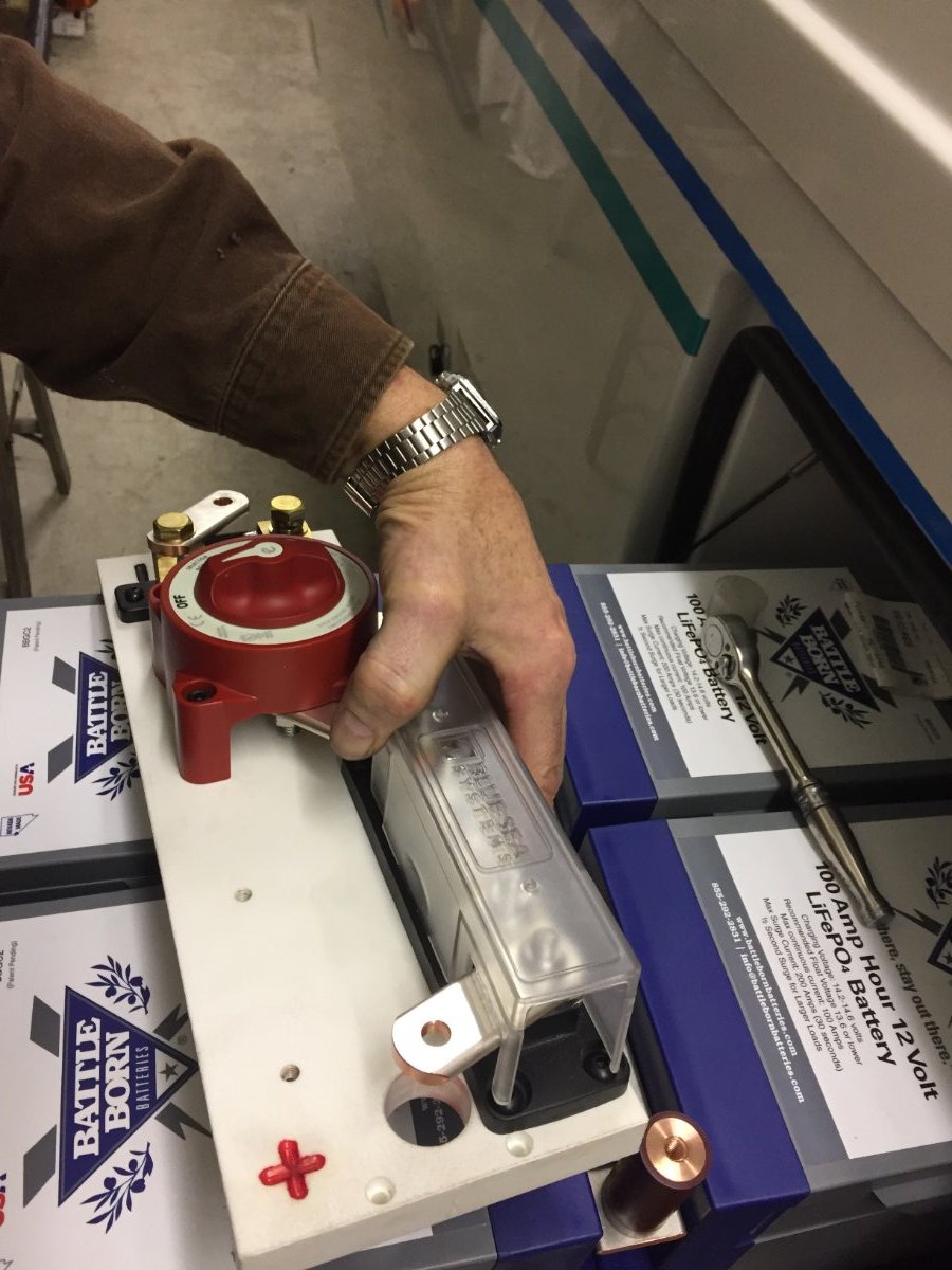
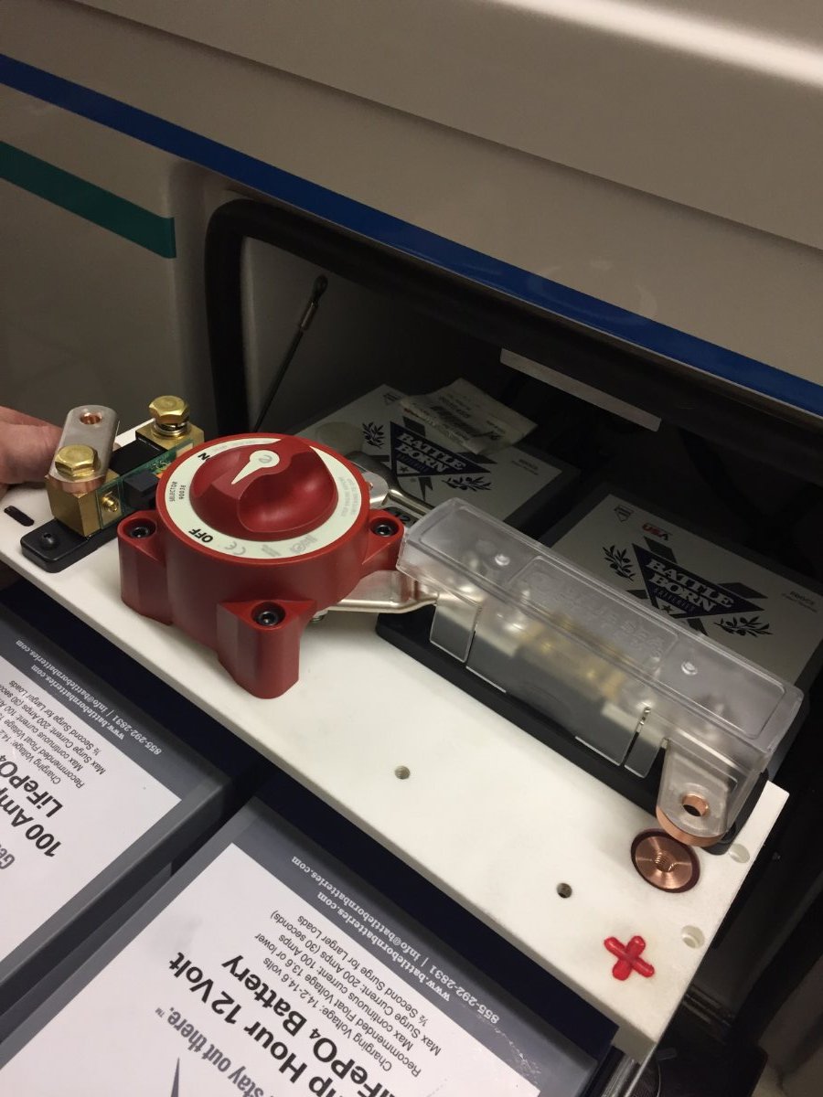
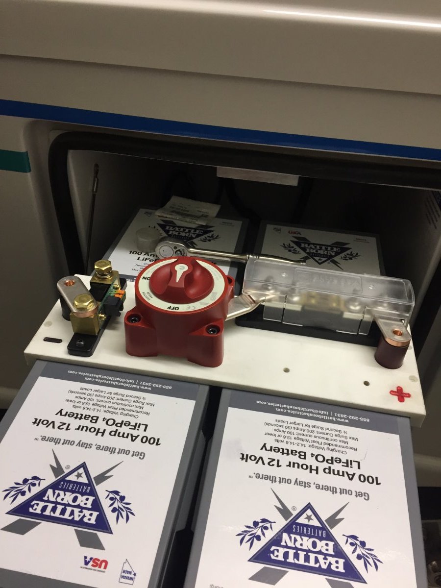
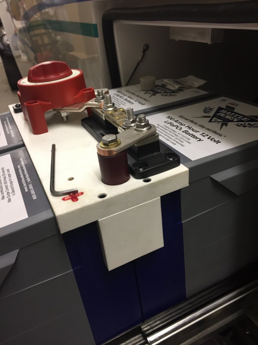
- Mounted main fuse in close proximity to the positive post of battery
- Mounted main battery disconnect in close proximity to the positive post of battery
- Added a positive and negative bus bar and moved all cabling to inside the basement except for the 2 main 4/0 cables. (I was able to exchange main fuse with a positive bus bar using the same mounting area, then moved the fuse out to the positive post of the battery)
- I used bus bars to connect the 4 batteries in parallel
- A strip of flat PVC was used to insulate between bus bars
-
3
-
13
-
Thanks for the warm welcome, Bill! I've appreciated your comments on the forums.
-
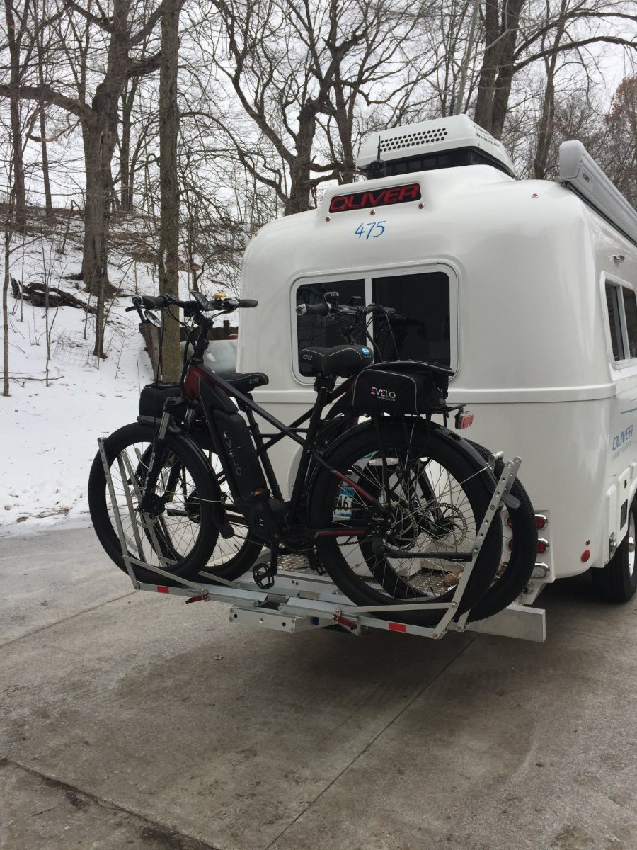
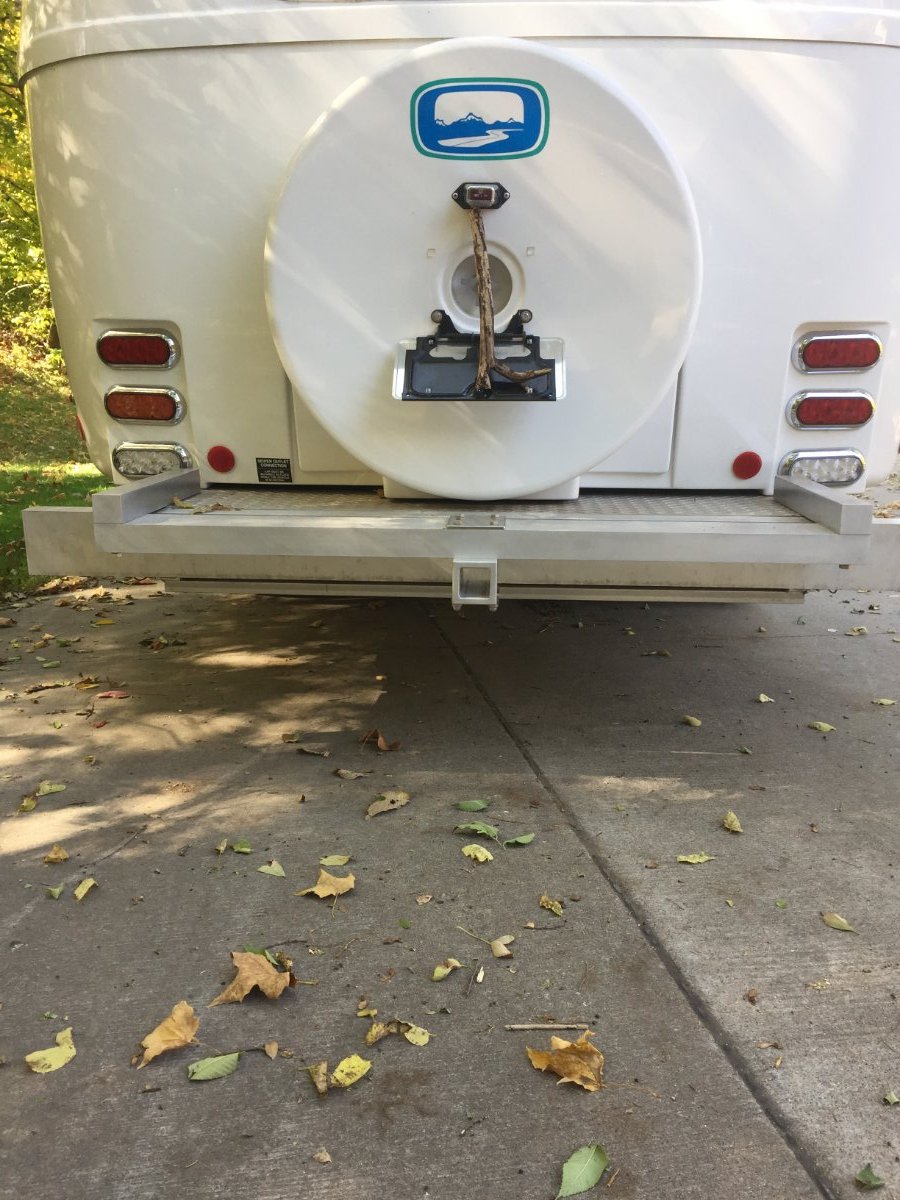
Sharing a modification to the receiver hitch that allows access to the spare tire without removing any part of the hitch, up-sized the receiver to 2 in, and heightens security against thief.
It may not look like it, but the access to the sewer outlets is still functional.
-
5
-
-
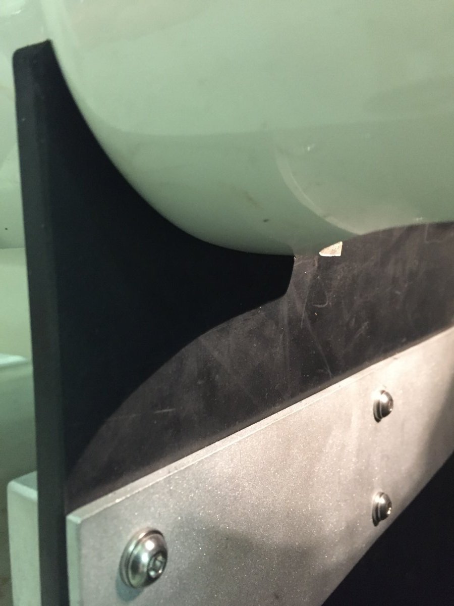
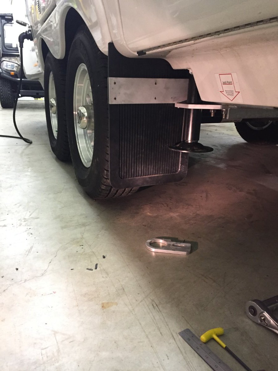
Sharing my modification to bring mudflaps closer to protect everything beyond the wheel well.
-
3
-
10
-
 1
1
-
.jpg.b4fb182c2dd38b005d42f99a3317e409.jpg)


.jpeg.ecac4362e715bf0263438706bed3777f.jpeg)


.jpeg.8b7f7e108535c1dcc1fffbc9041ff791.jpeg)


Breaking Subzero | Oliver Furnace Mod
in Ollie Modifications
Posted
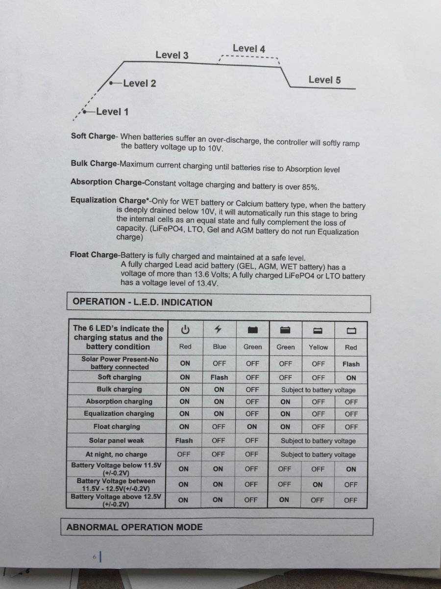
It is piece of acoustical insulation that was for large generator enclosure, it was 1-1/2" thick and 19" square. I believe It is open cell foam with a black finish that seals the cells on the one side and the other side has adhesive applied with a plastic tear off sheet. Just the edges would have exposed open cell, I would not expect the R-value to be very high but it did the job. If you look at the chart I put up It stayed in comfort range that Battle Born recommended and it sealed the opening with the water proof adhesive backing facing my door vents, plus easy to install and remove.