Search the Community
Showing results for 'Generator box'.
-
An interesting and neat looking storage area. How much does the new storage box and mounting system weigh and how much weight will you be able to safely carry in the box? Thanks!
-

Generator Inverter Usage
rich.dev replied to Wandering Sagebrush's topic in Mechanical & Technical Tips
If you have the Xantrex inverter I believe you have to change the AC input setting, that would be # 28 setting in the Xantrex FXC Control app. Your 1000W generator at 110V is only approx. 9A, the Xantrex (my 3000W anyway) is factory set to 25A because the breaker size for the inverter is 25A and the main power supply is 30A which is greater than the breaker size. So when you connect to a generator or house receptacle that supplies lower amps, you need to adjust setting #28 down to match the current incoming power supply. Or like @dewdev said, shut off the circuit breaker to your inverter. -
 I've had my heart set on a Ram 3500 Cummins HO with the Aisin transmission for a while now, but haven't pulled the trigger on the truck or the LEII yet. On the truck side I've been debating the following: Dually - Dual Axle (DA) vs Single Axle (SA) Crew Cab versus Mega Cab. 6'4" Box versus 8' Box There are three important caveats, You can only get the Mega Cab with the 6'4 box You can only get the 50 gallon Diesel tank with the 8' box. The 6'4" box comes with the standard 30 Gallon Tank. You can only get the Mega Cab starting with the Laramie trim, there are 2 lessor trim packages which could save $ Lengths: Crew 6'4"box- 19.75' wheelbase 149.5" Crew 8' box - 21.73' wheelbase 169.5" Mega 6'4" box - 20.82' wheelbase 160.5" I was leaning towards the single axle Mega Cab with the 6'4" box, but that requires at least the Laramie trim package, which I don't necessarily want. Also I really would like that 50 gallon tank, which puts me back to the Crew and 8' box which allows me to save some money and get back to the Tradesman trim. Having said all that, 90% of the time, there will only be 2 people in the truck and the Mega Cab really only benefits back seaters. Unless of course you put the seats down and use it as a flat space for storage. I wanted to see what you experienced Oliver haulers thought about these options. Any opinion on the wheelbase differences on towing or driving around town? Or is the 149.5" wheelbase already so long adding another 20" isn't going to make much difference in towing. DA vs SA, I am leaning toward SA mainly because of the rear width size during non-towing everyday driving. However, I would also appreciate any opinions on this as well. Any thoughts on the 6'4" box vs 8' box, in terms of running out of space? Everyday driving? U-turns, etc.
 -
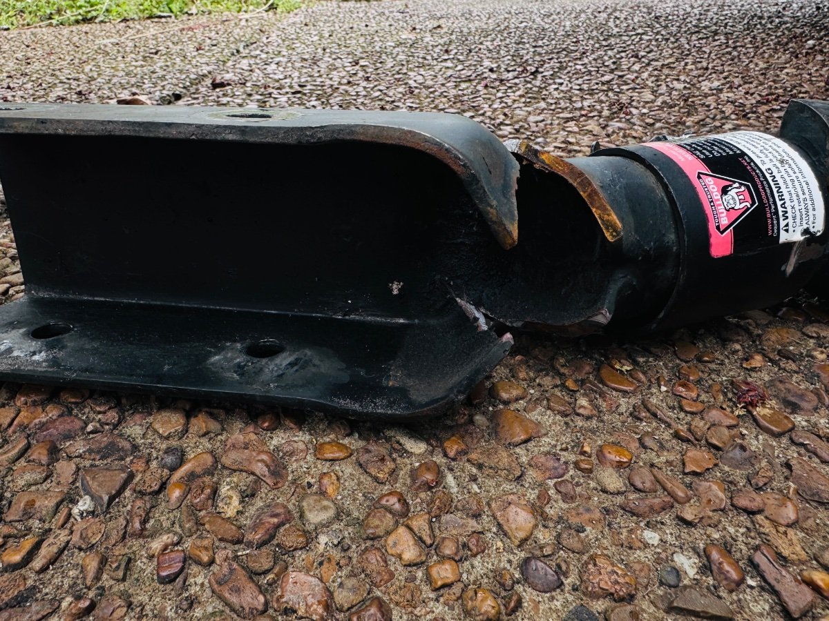
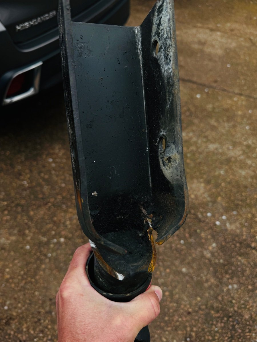
@mountainoliver @Steph and Dud B That is very interesting. Mine definitely did not have that gusseted welded section where the break occurred. I wonder when they made the change and why they didn't put out a recall if that is the case. Or mine was just defective from the factory. More pics of others pre-2018 might be interesting. @Geronimo John I didn't see any signs of galvanic corrosion. Bolts, aluminum and steel around bolt sleeves looked good to me. @MAX Burner I am just curious. How can the max tongue wt max be 485 lbs when the TT dry is 4900 lbs. A basic rule of thumb is tongue wt max 10% of total wt. Through various online sources, I have always considered the V-8 Tundra's to be in the 600-700 lb range. I would appreciate any input on this. I mean if you can overload your max tongue wt with a 55lb generator in the front basket I would be shocked again. And correct me if I am wrong, the Tundra pulls the Ollie incredibly well without a sway bar or WDS. SO why not just OEM the 2-5/16th coupler instead of the marginal 2 in. Lots of variables here to think about for me personally and fellow owners as well. BTW, we are back home safe and sound in good ol' Tennessee!

-
It had nothing to do with your failure but I’d seriously consider adding a WD hitch to your trailer. You have a lot of tongue weight with your front storage box loaded, well above what’s recommended for a 1/2 ton.
-
My wife and I have been lurking for awhile, but wanted to join to be able to interact some with y'all 🤗 Both of our kiddos are in college now. And so, of course, we see a window of opportunity opening for new adventures! 💯 We've considered many options including: Class A, Class B, Class C, van conversion, school bus conversion, box truck conversion, minivan conversion, etc.. We are now leaning towards pulling a trailer for the convenience of not having another engine to maintain and the ability to leave the camper behind at campsites for excursions, as well as to be able to use the tow-vehicle as a daily-driver when at home. My wife wants me to build a custom trailer, which sounds like a fun project, but one that would likely take a long time to complete! The LE2 seems to be a good rig. Loving the fiberglass shell. Looked at other fiberglass shell models, including Scamp, Happier Camper, Casita, Bigfoot, Barefoot, and Escape, but there's always something not right: too small, too wide, not tall enough, yada, yada. I'm sure you know how it goes. Please be on the lookout for our posts!
-
It seems that not everything that this video claims to be is nor accurate. I can’t recommend this product.
-
Made in USA leaf springs
MAX Burner replied to Mountainman198's topic in Mechanical & Technical Tips
Good discussions and points of view regarding this "OTT Spring Issue". What a great group!!! Speaking with Mike, I asked about ALCAN's track record, and can confirm @Patriot's comment that indicated they've never had a set of springs returned. Don't think Dexter can make that claim. But that's not the only reason why we're upgrading our suspension with ALCAN 5-packs. OBSERVATION: There may be a couple "OTT owner" camps here - there are those owners that purchased their rigs new from Oliver and those, like us, that bought used. Those buying new know exactly where their rigs have traveled, they know the level of maintenance performed over the years, and they know what's been broken, replaced, and upgraded. OTOH, those owning 2nd/3rd-hand Olivers have absolutely no clue how their treasured rigs were treated by previous owners, at least we sure don't. That said, especially concerning running gear, we don't take any chances and err to the side of safety. Short of taking our springs to an NDA lab for analysis (not a cheap date, either) - we've decided to go with the ALCAN 5-pack upgrade for peace of mind. For those that choose not to have their springs NDA-inspected, having a spare in the bottom of the tool box might be a prudent action, IMO. Totally agree with @hobo's assessment - $'s well spent. 'Nuf said here.... Cheers! -
I also purchased new battery terminals, crimped new lugs on all cables and new battery hold-downs, since they were all pretty crusty (see pics). The new batteries did not fit the OEM hold-downs (new Dorman hardware), so if you look closely, you'll see I had to rig some inserts to hold them tight. I went with Military style terminals. First experience with these, and I love them! I purchased this item but would make another choice next time. Great terminals, the rubber covers are decent, but the lugs and heat shrink were not of best quality. Dodge Cummins Military Dual Battery Terminals, Lugs & Boots | eBay These terminals have a 3/8" bolt end, so use 3/8" lugs on all your cables. The other side has a 5/16" bolt to tighten the terminal on the battery post. The beauty and simplicity here is that you can keep the 3/8" cable end held tight, and merely loosen the 5/16" nut to remove it from the battery. I've been fighting cables on dozens of vehicles since the70's! I purchased another couple of sets to use on our other old cars and trucks in the future, to be installed each time we need a new battery. The other thing about Group 27 vs. these H7 AGMs is the posts are in reverse orientation. In making all new connections I had the change the +/- location of all cables. The main + cable, connecting the two batteries, mounted over the radiator core had to be shifted about a foot over. I had to make a new cable from the LH battery to the power distribution box, but most other cables had room to move 10" left or right. I think it came out pretty good. The AGMs should last much longer. Every time I park the truck voltage is 13.1V or better, where LA is usually 12.6V at best. Let it park for a few days (and I have a cellular router running, rid-rat devices and more) and it's still at 12.9V. Love the AGMs! What do you think?
-

Oliver batteries not charging with generator
Galway Girl replied to chiwald's topic in Mechanical & Technical Tips
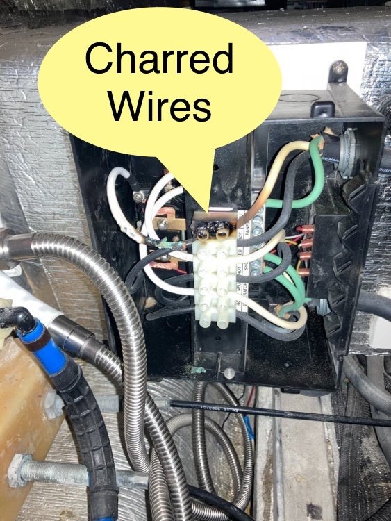
As a safety check as you contact Oliver. There have been a few of those under the dinette transfer switches that failed due to loose wiring connections inside and had thus melted internal wiring. Transfer relay wires can wiggle loose and cause the switch to toggle back and forth when power is applied. To check, you would need to disconnect from shore power and generator, then open the transfer switch box to check if its connections are tight and no smoked wiring.
-

Oliver batteries not charging with generator
topgun2 replied to chiwald's topic in Mechanical & Technical Tips
A couple more things to try - 1. have you simply shut everything off, unplugged the generator from the Ollie and waited at least 5 minutes to give all systems a chance to reset? 2. If it is the transfer switch (I doubt this because you've now had the same problem with both the front and side transfer switches on your Ollie) and you have a rubber mallet then you can hit (tap) the transfer switch box. This will help the springs inside the switch snap back into place if they are "stuck". -
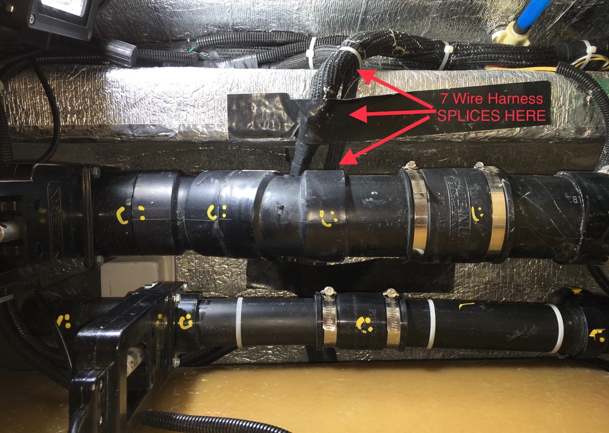
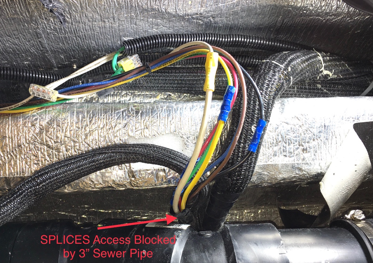
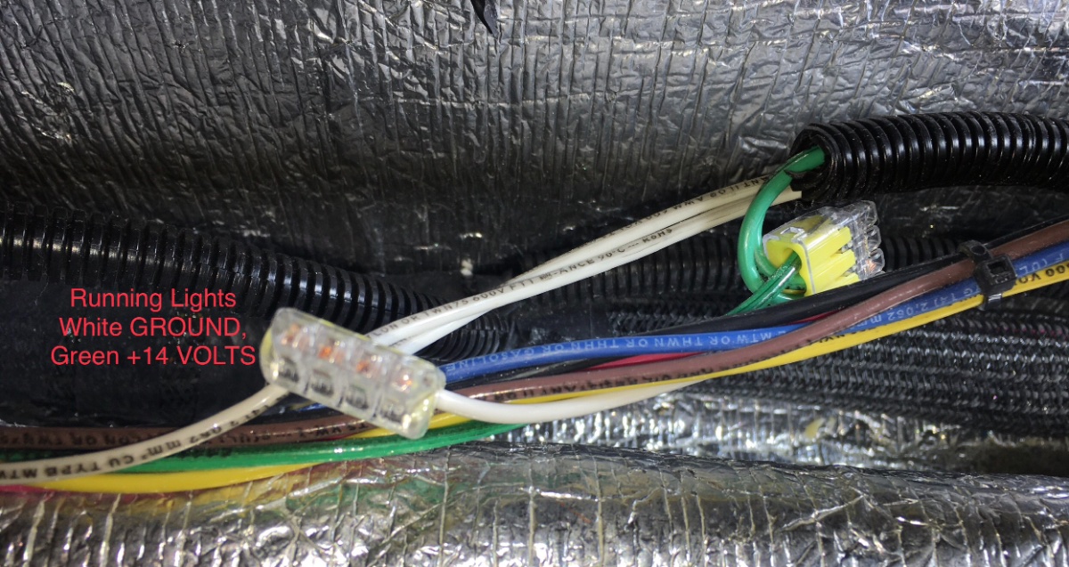
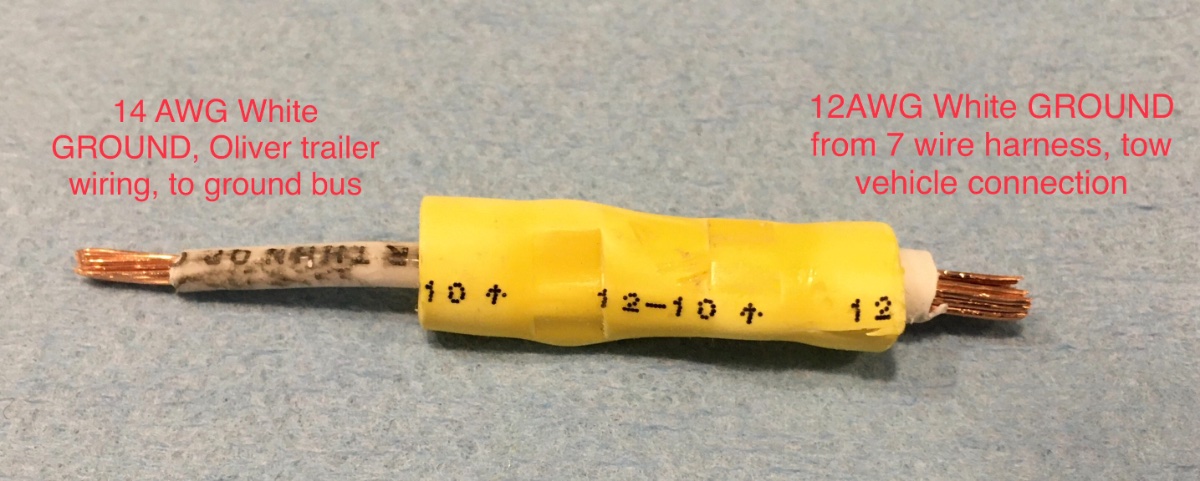
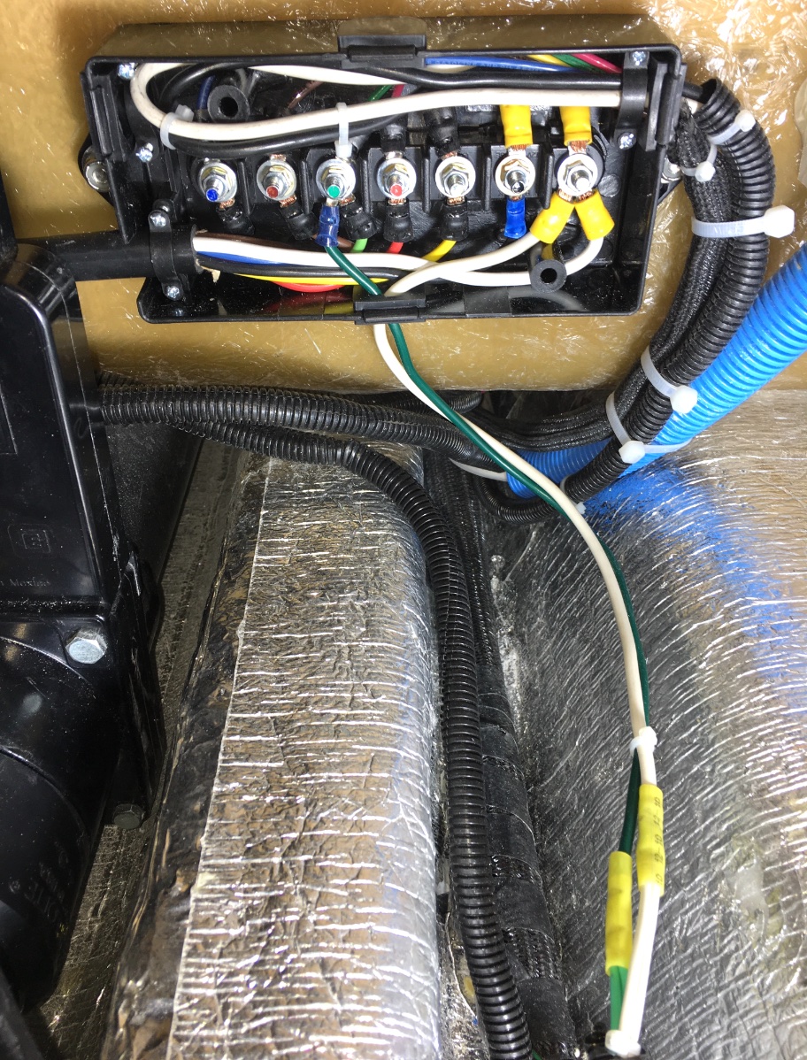
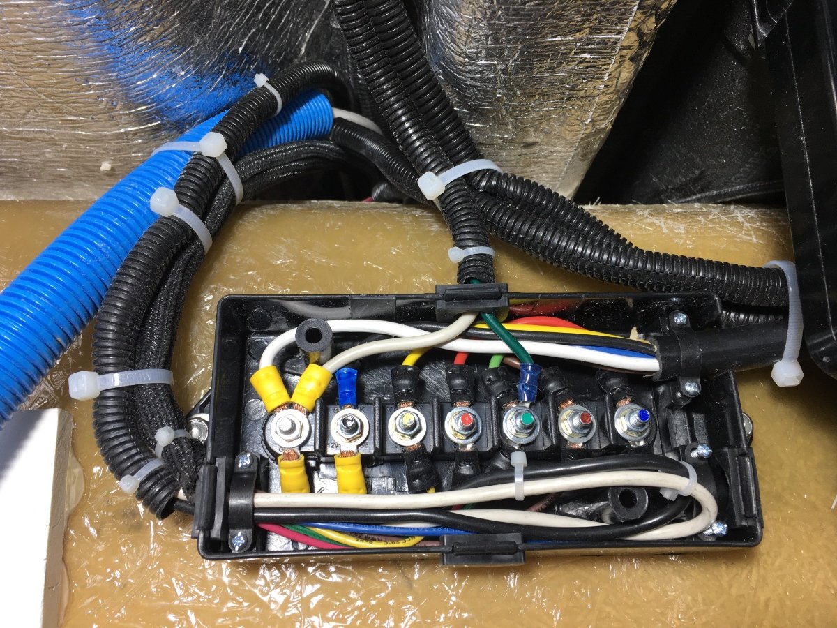
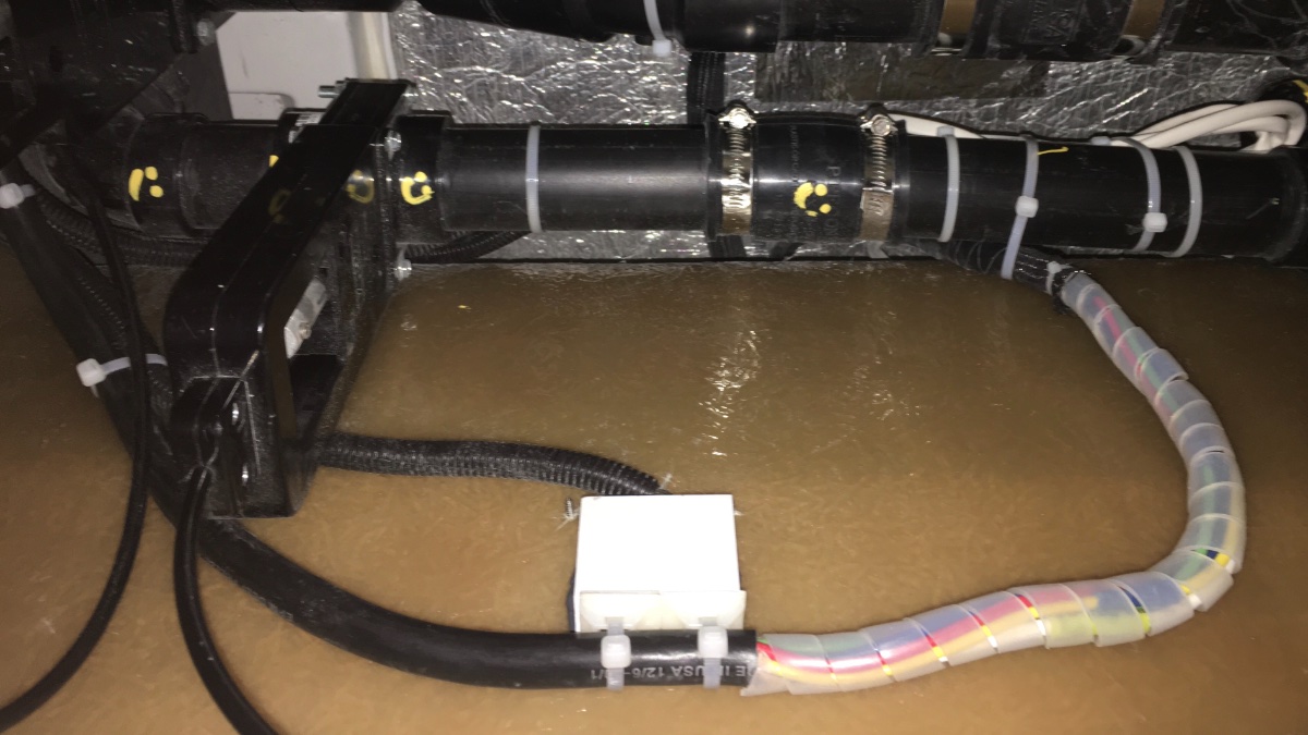
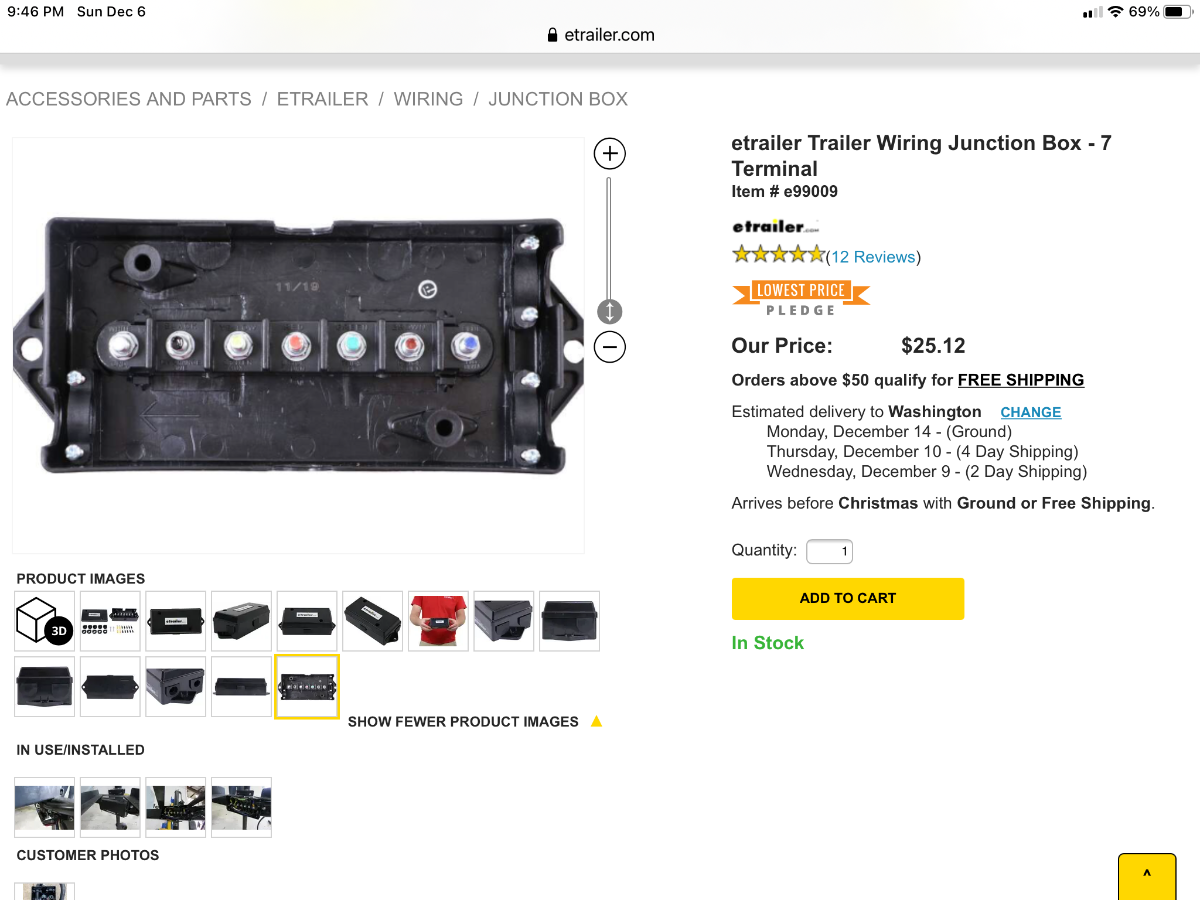
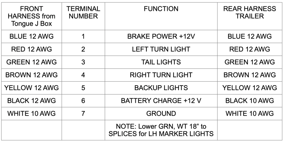
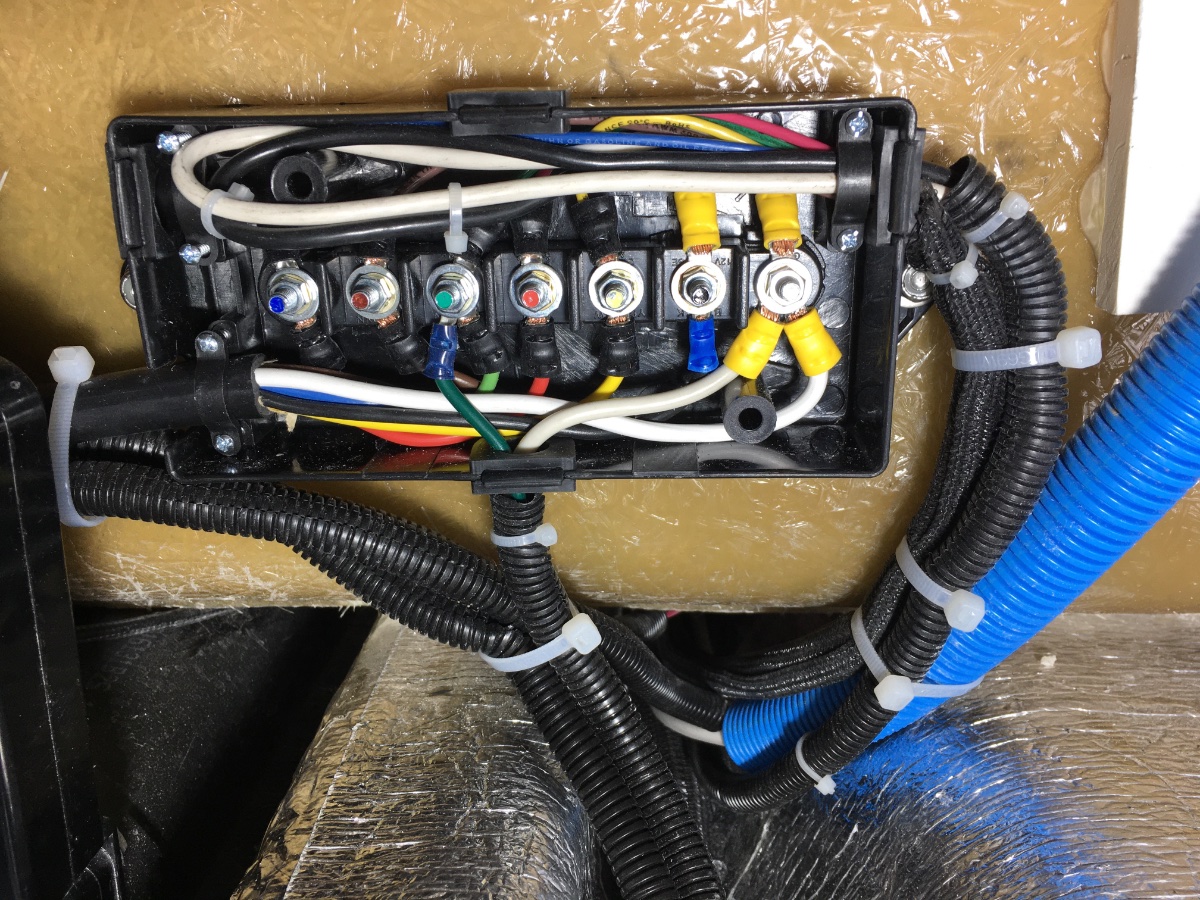
 Here is a related thread, I installed a similar box up front under the jack: ... https://olivertraveltrailers.com/forums/topic/2688-how-to-junction-box-for-trailer-harness-repair-or-extend-the-harness/ This all came about because I wanted to install a ... Redarc DC to DC Battery Charger .... and I needed to know FOR SURE that the wires were big enough. 12 AWG is the absolute minimum according to Redarc, and bigger is always better, especially in an Ollie with a very long run back to the batteries. Here are the existing butt splices, half of them are absolutely buried under the sewer pipes. Time for a J-Box! So I cut all the splices, and dragged the ends up to where I could inspect the wires. Most were OK, but the white Ground wire was not. Somebody extended the front wire with a smaller sized one. Darn it! I bolted down the box next to the 120 VAC outlet. I spliced into the green and white running light wires and brought them up to the box via the bottom hole. The other wires come in from the left and right sides. I ran heavier 10 AWG black and white wires (power and ground) from the box back to the appropriate posts. So now the Redarc charger will not suffer from excessive voltage drop, and with the easy access, it will be very simple to troubleshoot any future 7 Wire Harness problems. The new splices are easy to ID because they have clear spiral wrap plastic, and they are secured to the inside wall using a 1" thick block of HDPE plastic, bonded with JB Weld directly over the small LED light. The placard goes inside the J Box using 3M double stick tape. Here is the placard, in Apple Pages format: Oliver Junction Box wiring placard Rear 7 pin.pages Note that I indicated where those marker light splices are - I hate not knowing! John Davies Spokane WA
-

Oliver batteries not charging with generator
chiwald replied to chiwald's topic in Mechanical & Technical Tips
Okay we turned off the EMS and it is charging with the generator. Okay so what does that mean? How do I fix this for the future. I trust the generator is okay. Is there a reset for the surge protector? -
Oliver batteries not charging with generator
topgun2 replied to chiwald's topic in Mechanical & Technical Tips
OK - the data link error should not have anything to do with the charging problem. This error code only means that the remote display is not communicating with the main EMS computer. I do not have a generator, but, I still suspect that the issue lies with the either the generator or the transfer switch. Try what Steph and Dud B are telling you. Bill p.s. thanks to Steph and Dud B for trying to help out! -
Hello everyone, I'm new on here and excited to be a part of the community. I just placed an order for a small 2500 watt dual fuel Champion generator and plan on running it off of the propane quick connects. Will i need to get a diaphragm regulator? Anyone have advice and/or photos of their setup? Thanks, Happy Camper
-
It's been some time since we have had a towable RV. Our last was a 30ft fifth-wheel with plenty of onboard storage. Now that we are getting an Oliver, I'd like to know just how much do you use the pickup bed for carrying essentials. Our TV is an F350 SD long bed crew cab. It doesn't have a canopy or even a tonneau cover. It is also my husband's primary vehicle, aside from his motorcycle! A few theft-prone items I know we will be carrying: small toolbox, portable inverter generator, and fuel for the generator, bike gear, inflatable kayaks and gear. Other items I'm not concerned about: firewood, water jugs, Beyond these, what do you find you routinely carry in a pickup bed and how do you protect cargo from theft and the elements? For the tools, generator and fuel, a bed width locking toolbox would suffice. And we could secure the kayak/bike gear in the back seat. We're open to any and all suggestions. Thanks
-
GJ - Actually, THAT pic was taken in my workshop. The two holes in the "L" plate are from those self tapping screws that I put in place (the first time) through the 4 inch circle that I cut in the floor of the cubbie above the MW. I could never tell if the "L" plate is screwed hard against the MW cavity ceiling because you simply can't see in there once the MW is in place. However, if it is not hard against then it must be fairly close. The "problem" is that the two screws are the only thing holding the MW in place and the "case" of the MW is simple sheet metal. So, even if the "L" bracket is hard against the top there will still be flex in the rest of the MW cabinet which will place strain on the only other contact point(s) the face plate. I frankly was surprised by how much the MW still moved. But, bouncing down dirt roads let alone expansion joints on our super smooth interstates just might explain a bunch of things. No, I did not epoxy or "liquid nail" anything in place - the simple friction fit seemed to do the trick. All I was trying to do was to keep the MW from bouncing and it appears that I succeeded. If you try to do something similar to what I did - be mindful of trying to not restrict airflow too much given the heat that can collect in and around the MW. It is rare that I use my MW for longer than 3 or 4 minutes in one sitting. But, for years it was the lack of airflow inside this space that prevented Oliver from offering something like the convection oven that is now available. Bill p.s. In re-reading your comments above I'm thinking that a better mental pic of the wood box(s) into which the MW is placed might be of some benefit. Basically, it appears to be a box inside a box or at least a three sided box inside a box with the three sides being the top and (at least ) two sides - I'd bet on a regular five sided box with one side missing - the front where the MW slides in, but, since I didn't want to tear what was there apart, I really don't know. Having said this - I was a bit surprised when Oliver Service told me that I would need to drill a 4 inch hole in the cubbie above. And, when I drilled that hole (it absolutely ruined a 4 inch carbide hole saw doing this - that fiberglass in really touch stuff - I looked in expecting to see the area where the MW was located. All I saw was what turned out to be the top of the "wood box" I mentioned above. Blindly, I drilled pilot holes for the self tapping screws and that is where the two holes in the "L" bracket came from. Next, I was worried that I'd play hell getting those two screws back into those two holes when it came time to put the MW back in place the second time. But, (maybe luck was on my side) it was a piece of cake given that I (obviously) slide the MW right back into the same original position. Hopefully this helps. p.p.s. Where did you dig up that pic? A moldy oldie for sure. I had forgotten that I even took the pic.
-
I guess I'll check my springs tomorrow when it's dry out. I'm not sure how "good" my 2016 #110 springs are. I still need to install my EZ-Flex suspension kit I have sitting in the box. Need to pick up a new grease gun too. Great info on this thread. Thanks for sharing.
-
Now - this is interesting ---- I lined the metal box with aluminum foil with the exception of the lid. Now, when approaching the truck - about ten feet away - the truck's courtesy lights come on, the doors unlock and the running boards deploy. So, I didn't even get inside to see if the truck would start since my lined box failed even step one. Next I'll try lining the lid but that will have to be tomorrow. Bill p.s. thanks to Patriot for busting my safety bubble!
-

Faraday pouches for Tow Vehicle key fobs.
Mike and Carol replied to Patriot's topic in General Discussion
We ordered a box and two pouches that we’ve been using for some time. Car thefts are up around here, they get close to the house, do a scan for the key inside the house then drive your vehicle away. Our car and truck are in a locked garage, but the faraday box is extra insurance. We use the pouches when traveling. Mike -
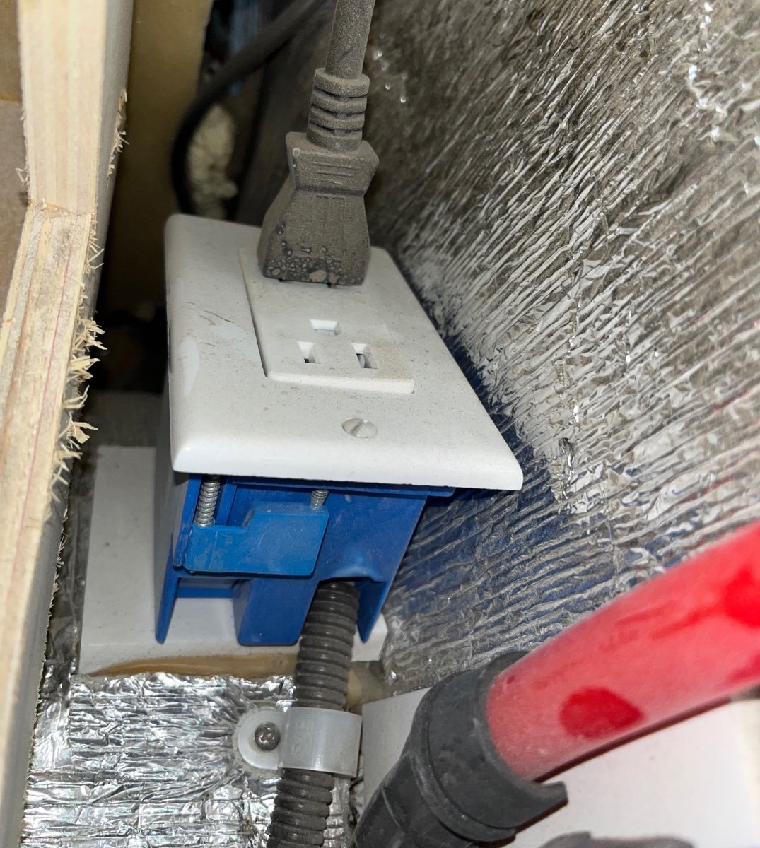
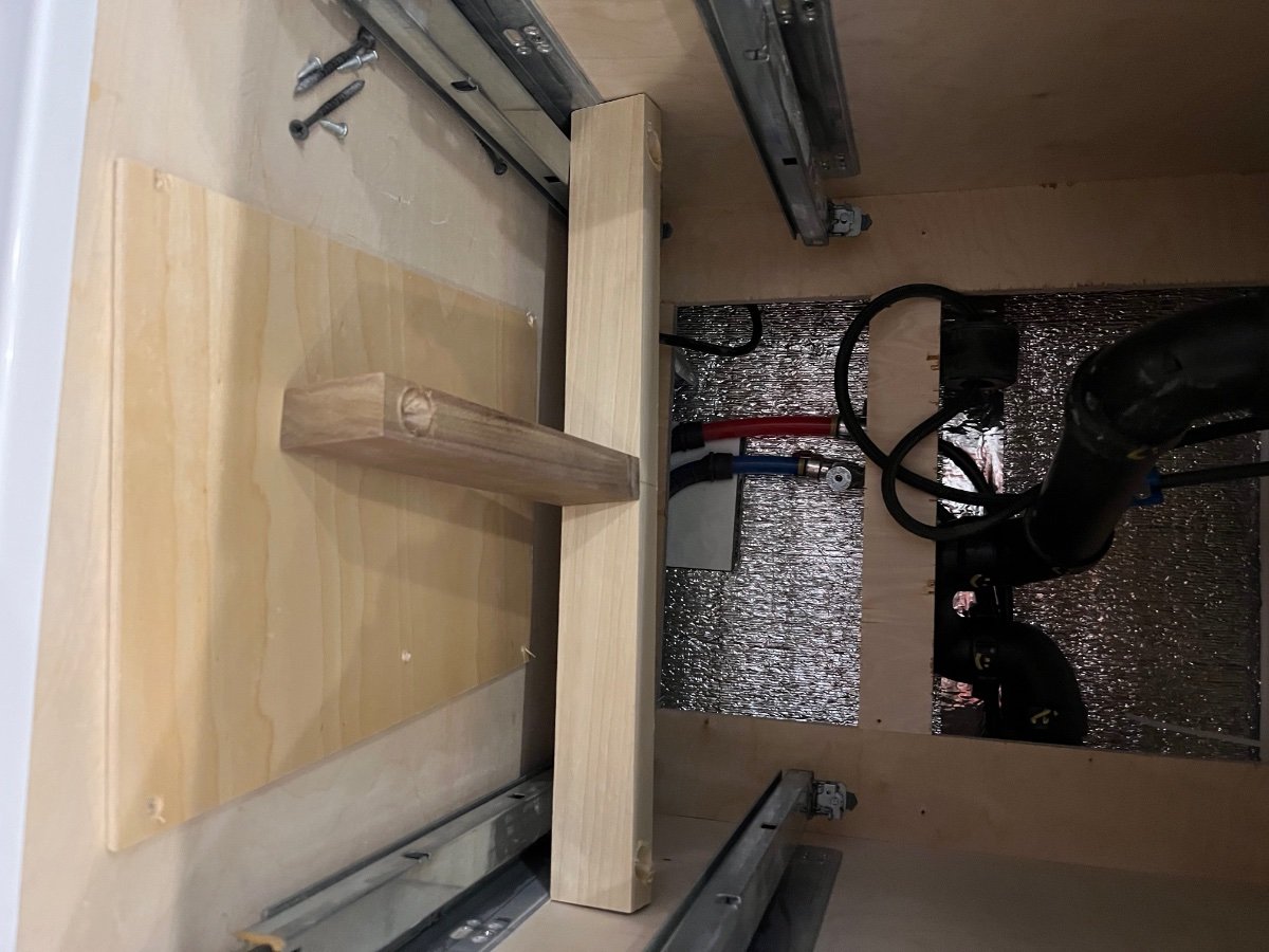
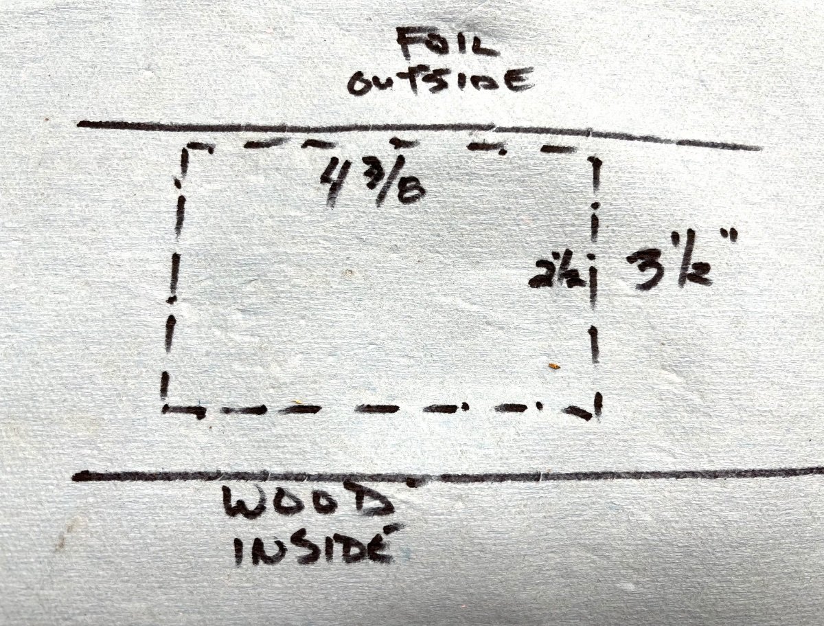
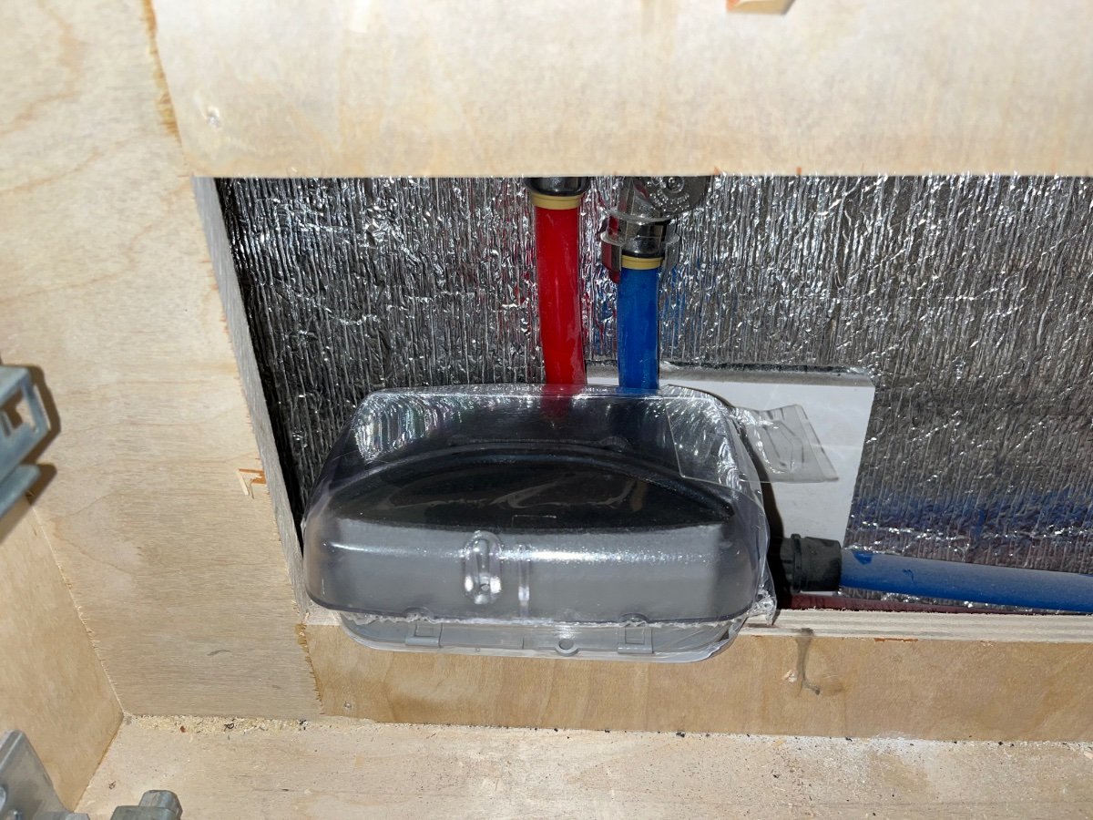
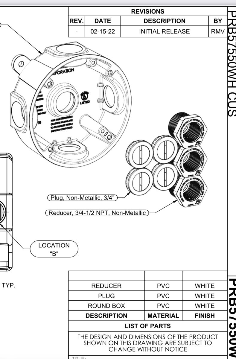
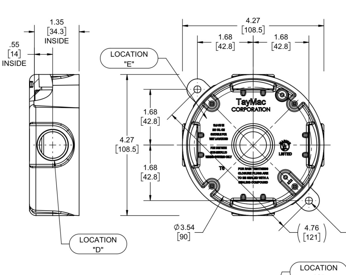
NEW JUNCTION BOX: This has literally been bugging me for five years, from the first time I saw a picture of the outlet mounted right below the faucet water supply hoses and the drain pipes. It is not even a GFCI outlet! If there is a water leak, it could be dangerous. Sorry for the rotated pics, some come through this way! Remove the two lower drawers by squeezing the orange release things, and lift up and out. Remove the flip out tray screws. Remove the tee piece (three long screws) and then the 1/8' plywood access panel. DISCONNECT SHORE POWER, double check to make sure these wires cannot be energized! Flip the main breaker to make sure! I measured the space and found that it is too tight to install a waterproof "in use" outlet cover. I even tried, I ordered one from Amazon, I can return it easily. Nope, it won't work. I decided to eliminate the outlet entirely. I am not sure why Oliver did not hard wire this in the first place...... I found this plastic junction box at Home Depot: Here is what comes in that kit: This is a true approved 100% waterproof cover; Dimensions. It is plenty thin to fit in that area. More to follow. John Davies Spokane WA
-
I saw this earlier in the day and have been waiting for someone else to challenge this statement. I agree with the general statement that as AC frequency increases, current will as well. It just doesn't apply to those of us who connect our camper to the power grid. Maybe if you were boondocking and running a crude generator the frequency could change with a change in load, but not if powered by the grid. AC frequency in the US is fixed at the power plant at 60 Hz (in Europe and many other places it's 50 Hz). As far as I know there is no changing the AC frequency with any of our appliances or by loads at the campground. The purpose of having the EMS display a code for frequency is because you could be running off of a non-inverter generator, such as a PTO driven farm generator. You can end up with high or low frequency AC power if the tractor's PTO turns the generator input shaft too fast or too slow. It's very unlikely that this is the issue. A normal multi-meter doesn't have a setting for measuring AC frequency. A specialized multi-meter or an oscilloscope would be able to measure AC line frequency. Most of us are not carrying those specialized tools in our camper. HTH, Ken (I took a couple of electrical engineering classes a long time ago as engineering degree electives. If I've got it wrong myself, I don't mind being corrected. It's not something I use everyday.)
-
Thought I'd wrap up this discussion with some more test data. It's been around freezing here the past few nights so I wanted to verify past results and include a baseline test with the original OEM setup with just the return by the furnace. Pretty much all original results (OEM return blocked, and two 6" returns added at the rear of trailer) were confirmed, with some minor variances, with curbside rear temps increasing on average 15 degrees, street side rear temps increasing on average 20 degrees, and the under sink area increasing on average 12 degrees. Floor temps at the rear of the trailer increased 14 degrees. These increases were from a cold start in the morning. To start, all under floor areas were about 5-6 degrees warmer than the outside temps, and 11+ degrees colder than the inside temps (I keep a small space heater running in the trailer in the winter). Interestingly, when I put the heating system back in its OEM configuration, and closed off my 6" test returns, this showed only 3 degree temperature increases in the rear curb and street side areas. So not so great there! Under the sink, however, had similar gains (12 degrees). So I think some return air must travel in through the spaces between the cabinet drawers and back to the area under the sink. In my 2015 E1, the cabinet box is open in the back so return air can pass through to that area. All this may not apply to some of the newer trailers, but there are a lot of older ones out there that could benefit from this mod if you travel when it's cold out. Just how cold one can go I can't say yet, but this mod will certainly help a lot and is very simple to implement. The E1 will be different than the E2 as the furnace locations are different among other things. The same principles will apply however, with high pressure (cabin) moving to low pressure (under floor), and the returns will just be located in different areas. Preferably, but not always, as far away from the furnace and supply outlets as is practical (depending what path you want the return air to travel). Thanks. Now I have some big holes to drill out...yikes! 🤯 Dave
-

Show us your furry traveling companions..............
Steve and Mary replied to Ollie-Haus's topic in General Discussion
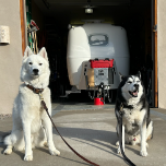
Ok, we can start the furry feline post. We have two Egyptian Mau cats, RJ is 16 and Sophia is 7. They always travel with us and love the adventures. Steve made a cat scratch post for them on the dining table stand. We open the door to our lower compartment and store their litter box there while being camped. On the move their litter box goes on the back floor of the truck.
-
 I wanted to share with you my recent battery replacement. My Ollie is a 2015 Elite II which originally came with Trojan T-105 AGM batteries in support of my solar system which utilizes the Blue Sky solar package (SB2512iX-HV MPPT controller and IPN-ProRemote). I replaced my Trojan AGM batteries with Bright Way Group Bright Way Group EVGC6 - 6V 220AH Deep Cycle Golf Cart Battery which OTT are currently installing on the Elite II as the AGM option. As part of this process, I contacted Bright Way Group technician in order to obtain the battery specification sheet (attached). I then provided it the Blue Sky Technician (Ryan Gurin, 760-208-2149). Ryan provided me with the settings needed to reprogram my Blue Sky MPPT Controller SB2512iX-HV via the IPN-ProRemote. Ryan is an excellent resource and was very helpful. I ended up talking to him multiple times. In a nutshell, here is what I did: 1. Disconnected the solar panel via the cutoff switch (street side bed) and opened fuses on the bus bars (also street side bed). 2. Removed the old Trojan Batteries (after taking pictures of the wiring configuration). 3. Cleaned all battery wiring connections. 4. Cleaned up the battery box and repainted the battery tray. 5. Inserted the new AGM batteries and made all appropriate connections (maintained the original wiring configuration). 6. Closed the fuses on the bus bars. 7. Reprogrammed the MPPT controller via the IPN-Remote using the new battery settings. (see attached sheet with adjusted settings) 8. Reconnected the solar panel via the cutoff switch. 9. Verified solar system was operating correctly and batteries were charging as appropriate. Additional Notes: 1. If changing to AGM from Wet Cells, you must ensure the equalization dip switch on the MPPT controller is off. You do not want to equalize AGM batteries. The dip switch will override the IPN-ProRemote settings. 2. Bright Way Group batteries have the same dimensions as the Trojan batteries so they fit in the tray (just as tight). 3. Recommend you review the Blue Sky Learning Center video on how to program the IPN-ProRemote. 4. IPN-Remote Programming instructions (attached) – please note I downloaded the menu sheet from the IPN-ProRemote manual and annotated the needed updates. I found it easier to utilize this menu sheet in order to understand where I was in the programming process (most parameters do not change). As you review, please note you should “restore default settings” first from the set-up menu. I have highlighted in yellow the menu options that you will need to perform an action on. The new settings are also highlighted in yellow next to the appropriate menu box. Hope this helps anyone considering replacing their AGM batteries. 1492893628_BlueSkyIPN-ProRemoteRe-programming.pdf BWG_Spec_Sheet_BW EVGC-220A-AM Final.pdf