

Minnesota Oli
-
Posts
106 -
Joined
-
Last visited
-
Days Won
4
Posts posted by Minnesota Oli
-
-
This is what I used this space for.
-
 1
1
-
-
Here's a paragraph from Got Earplugs by katanapilot from My version of the Houghton AC install posted May 27.
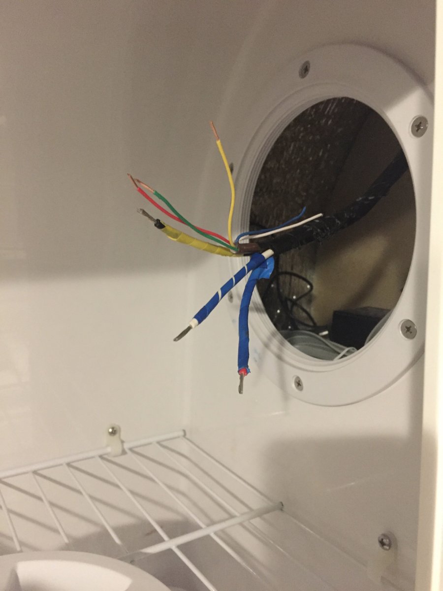
As a sidenote halfway through the install I thought of a different way of doing the wiring for the thermostat. If a person replaced the LCD thermostat with a older manual style you could do away with the LCD relay board. If you look at the first picture that shows a group of wires that are in a black sheath, these are the control side of the wiring for the AC. In that group of wires there are two blue wires one with a white stripe. The one with the white stripe is hot 12 volts DC and the solid blue is the wire that goes to the furnace relay board. So re-allocate the existing thermostat wires by doubling them up ,two of them hooked to the solid blue and the other two hook to the blue with the white stripe. Then at the wall hook the two thermostat wires that are hooked to blue with white stripe to the power in on the new manual thermostat and the other two to the power out. The reason I would double them up is because of they're small gauge. This would do away with having to pull wires and using the LCD relay board. Also save you having to toggle through the unusable modes (heat strip, cool) on the LCD thermostat to get to the furnace mode.

By re-allocate the existing thermostat wires and doubling them up ,two of them hooked to the solid blue and the other two hook to the blue with the white stripe. Now you are able to utilize wires that are already there saving you having to run new ones. Simply switch out the thermostat with one that does not need a control board.
Paul
-
3
-
 1
1
-
-
20 minutes ago, wolfdds said:
@Minnesota OliWho did you purchase your Houghton from?
-
1
-
-
I would take a look under curb side bed and make sure the heating ducts are still attached to the furnace.
-
1
-
-
8 hours ago, ChrisMI said:
It looks like the Houghton models spec out at 1370w and 1550w for the 9.5 and 13.5. The dometic 11k list out at 1382w. @Minnesota Oli was the amp draw on the low setting and did you replace a 13.5 or 11k unit?
My old AC was 13.5 Dometic the new is Houghton 13.5 I had the fan on auto and the compressor was running and it was show 10 amp draw.
-
1
-
1
-
-
9 hours ago, 2008RN said:
Minnesota Oli:
1. Did you leave the ends of the flexible heating pipe open?
2. Was the only other opening the hole in the straight pipe, or did you poke any holes in the heating pipe around where the check valve are at?
3. Where did you source the mounting bracket holding the straight tube below the battery compartment?
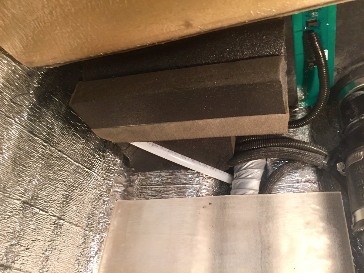
Yes I left the ends open. I added two additional runs to the furnace. One was a 2 inch which ran literally on top of the water pipes that run across the back of the trailer and ended pointing into the trough where the city water and freshwater and their check valves are located. Because of that area being covered by the floor of the storage area it forms a tunnel which the other end comes out right below the outdoor shower valve, so the heated air flows by all the plumbing in the tunnel and rises to warm the whole area around the outside shower valve. The other run was a 4 inch because it was a longer run, it was directed to go by the outdoor shower plumbing on its way past the battery compartment. That was the only place in the duct where I put a hole for flooding heat under the battery compartment. The 4 inch continued on towards the front of the trailer until the foot well of the dinette where it needed to be reduced to fit into the small trough so it could continue its way to the front to flood the area around the bathroom plumbing. When reducing to two inch there was room to add two more pipes to flood the area on ether side of the black water drain pipe which also formed a tunnel under the dinette foot well. This brought additional warm air to the front end of the trailer. My thought was to rely on heat radiating from the duct work to help keep the plumbing from freezing, but also flooding key areas.This is mimicking what the factory did on the curbside but neglected on the street side. One other positive side effect of adding the two extra heat runs was that the furnace now runs quieter,less forced air noise.
The question about the mounting bracket, this is something that I fabricated in my shop.
Your question about maybe less condensation on the walls, all I can say is overall the trailer was way more comfortable the bathroom was warmer and while sleeping in the street side bed there was not that chilly wall to contend with.
I highly recommend that Oliver owners should do this modification to the heating system, it's not that complicated pretty simple and straightforward with great results. It was enough to make the four season Oliver truly four season.
-
1
-
1
-
-
9 minutes ago, SeaDawg said:
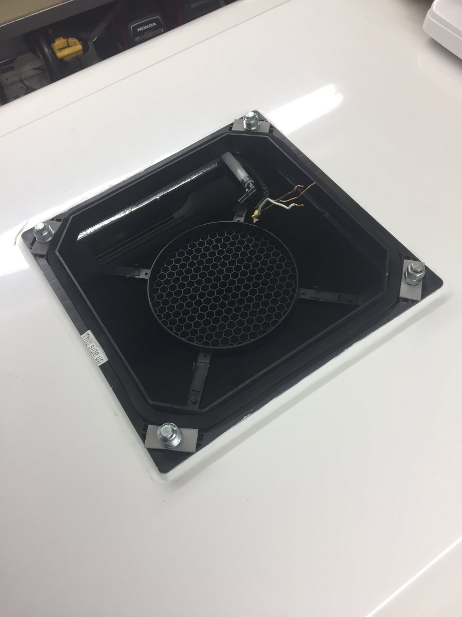
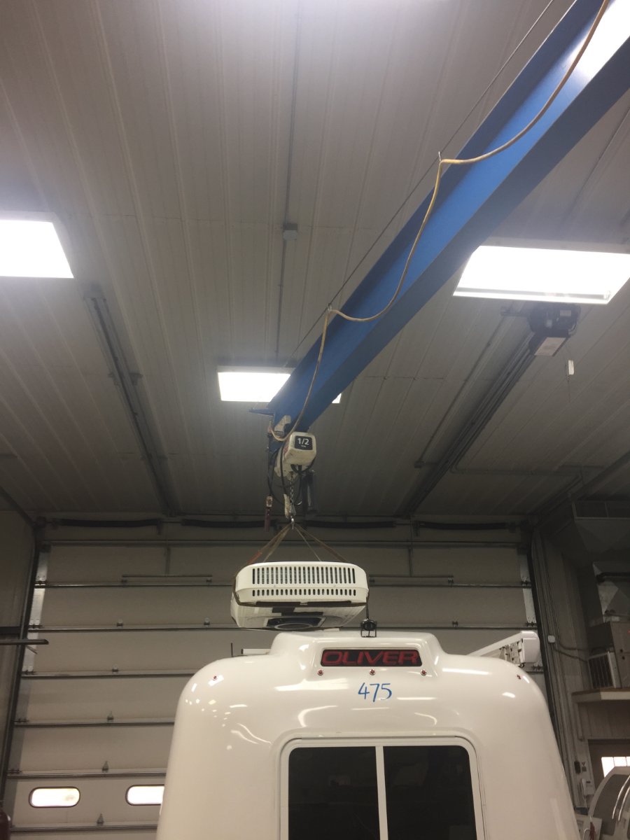
Looks great, with your low profile fan, too.
I'm curious about the relatively short cycles. We haven't experienced this, but we have a smaller unit, and smaller trailer.
I'd like to see a wider range in temp with the thermostat setup. We haven't been able to use our Houghton, much.
Yes I was thinking about the short cycles also and a possible explanation would be the trailer internal temperature had not stabilized yet since I only stayed long enough for it to drop to temp set on thermostat. I did stop in to check the batteries couple times during the 6 hour test but neglected to check cycle time. I have also not used it much ether.
-
1
-
1
-
-
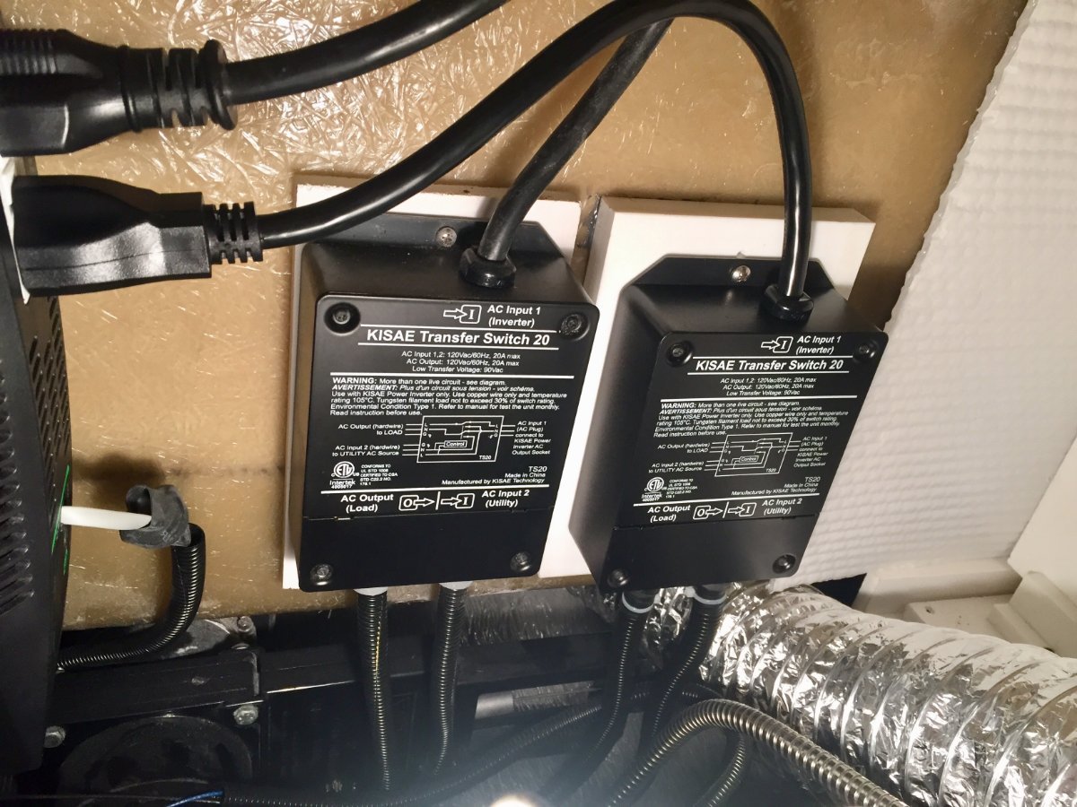
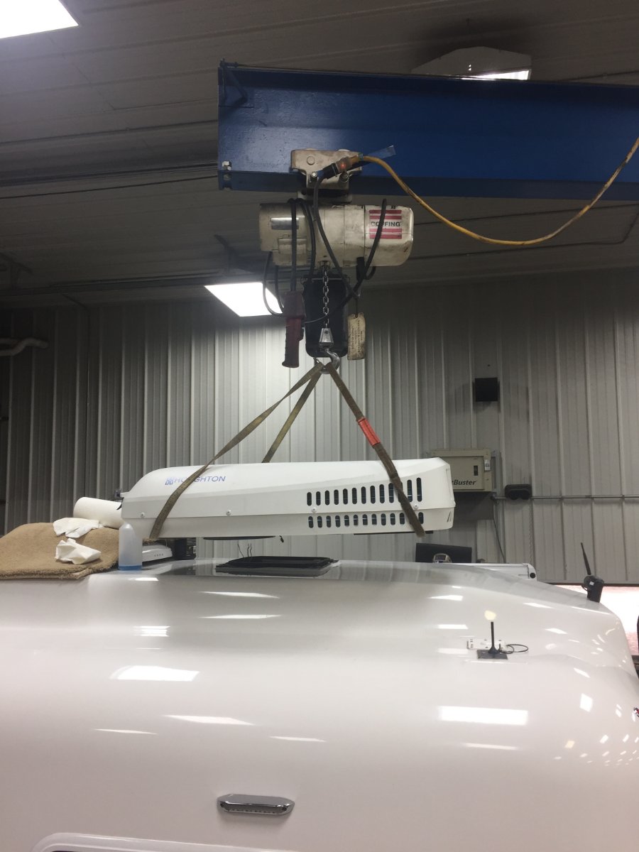
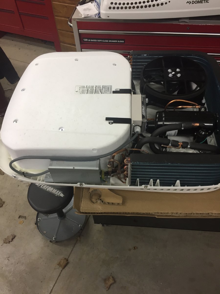
Besides the huge improvement in the sound level there is also another area where it surpasses the Dometic AC that I had replaced. The Houghton with the compressor running draws 10 amps while the Dometic was pulling 16 amps. So I decided to install a second transfer switch for the air conditioner to test it running off the batteries.
It was 11 o'clock in the morning on a cloudless sunny day the temperature was 88 degrees. I had my batteries 400 Ah fully charged with 340 watts on the roof and 230 watts remote ready to feed it. I set the thermostat at 70 degrees and turned on the AC. Once it brought the temperature down to 70 I noticed it was cycling four minutes on with the compressor and four minutes off. I left it running until about 5 o'clock and was surprised to see that the batteries were at 97 percent. So I was happy with those results but time will tell if that is the norm.
I put the picture in to also show it's nice low profile.
Paul
-
3
-
5
-
-
15 hours ago, mossemi said:
Nicely done but I have to ask, what’s the coiled duct work for? Is that heat for camping up north?
Mossey
Thanks. I try to share some of my projects to give back to the Oliver forum for all the great info and ideas I have gleaned from it.
To answer your question yes that is part of an upgrade I did to the heating system. Last winter here in Minnesota I was able to test my heating modification in sub zero temperatures. I loaded the Oliver with water and with no added insulation I spent 2 1/2 days in temperatures reaching negative 12 below zero. This was done using only battery and available solar to power the trailer. If interested check out Breaking Subzero | Oliver Furnace Mod under Ollie Modifications.
Thanks Paul
-
2
-
3
-
-
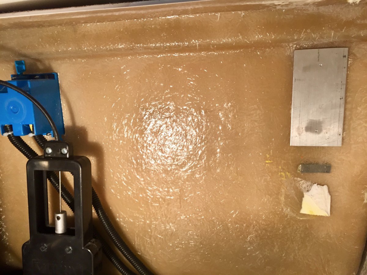
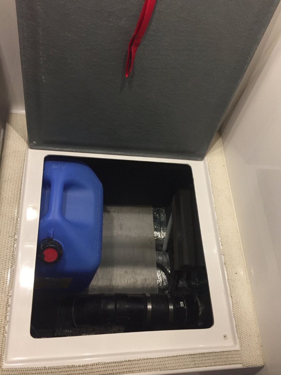
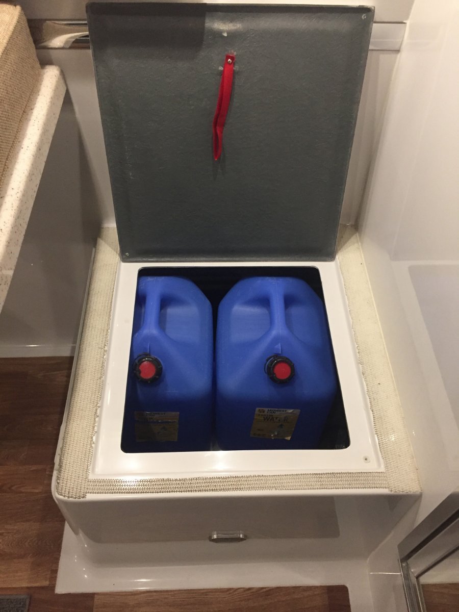
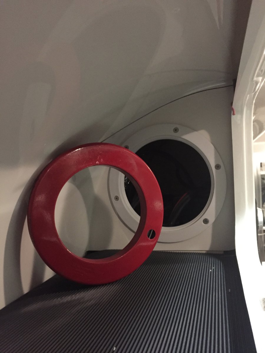
We prefer to bring our water from home which is filtered through ceramic filter. We use 6 gallon jugs to bring a supply of water with and then have smaller glass containers for our daily use, one is kept in the refrigerator for drinking water the other on the table for coffee or cooking. So to free up some space in the closet I decided to utilize the space under the dinette seating. To be able to accommodate two jugs I would drop the first one in the opening and slide it towards the foot well and then have the room in the opening to drop in the second one in. To accomplish this I had to remove the obstacle which was a receptacle box for the ground fault outlet. I relocated it to the opposite side on the same wall. By the way this was the first time that I cut any fiberglass on my trailer. It wasn't as bad as I thought it would be. I then made a aluminum backer plate so I could use a blank cover on the front to fill the hole that was left.
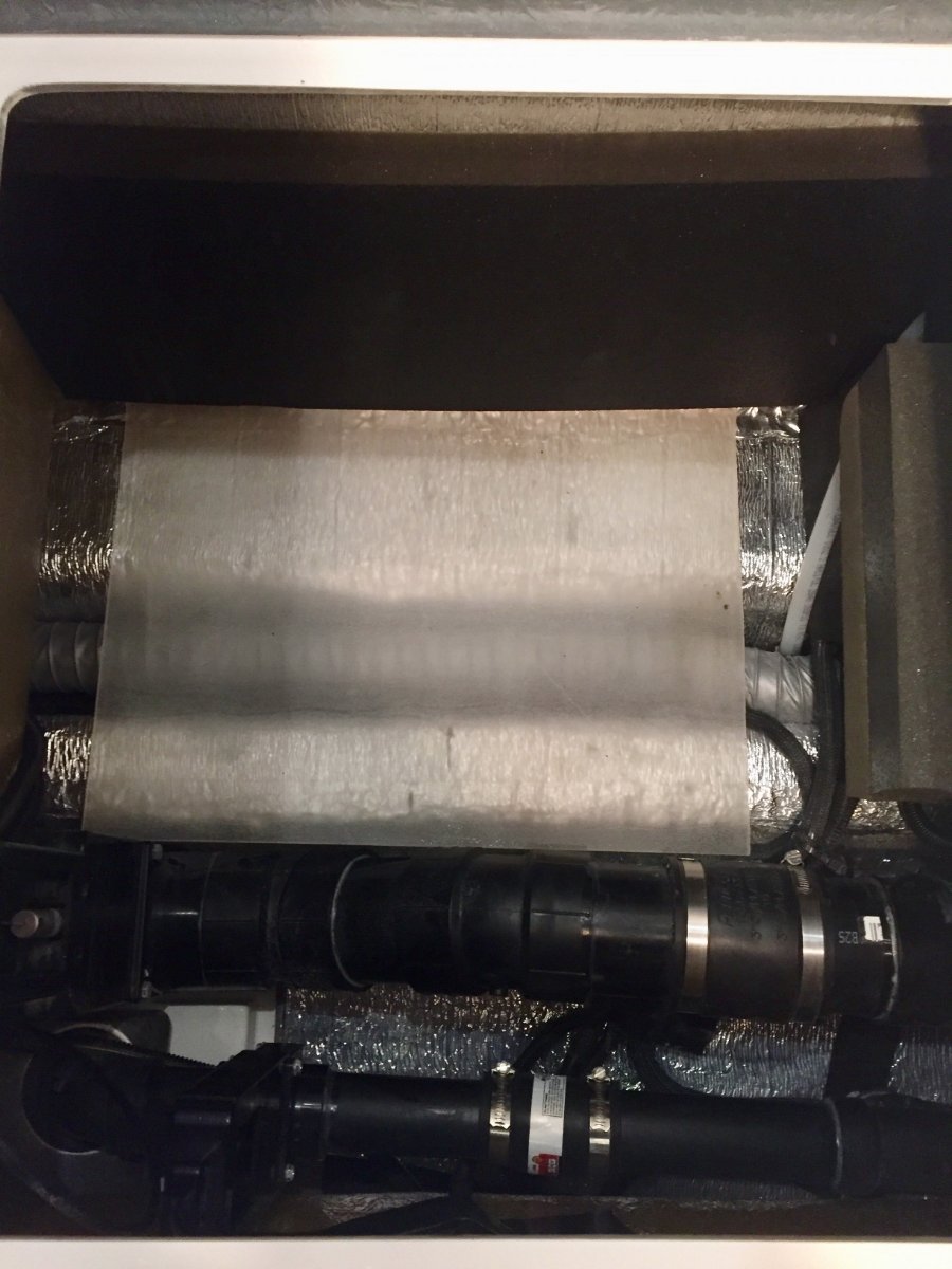
My next concern was to protect the insulation on the floor of the compartment, so I decided to fit a piece of quarter inch plexiglass that I had on hand
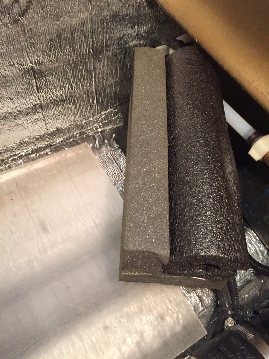
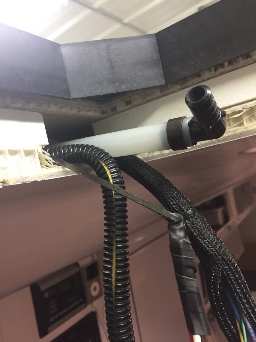
The last step of the project was to make a bookend to stop the water jugs from sliding forward. Here I used a short piece of 3/4" foam water pipe insulation and added some pieces of adhesive backed one inch foam to form the back stop, this is slipped over the black tank back flush pipe and butts up against the black water tank.
There was one other obstacle, there were a series of wiring harnesses that came up out of the trough and were tethered with tie straps and screwed to the floor and then went off to various locations I had to undo the tie straps and gather enough slack to move the harnesses back far enough to clear the area where the plexiglass was laid.
What am I going to do with all the extra space in the closet?
Paul
-
3
-
6
-
-
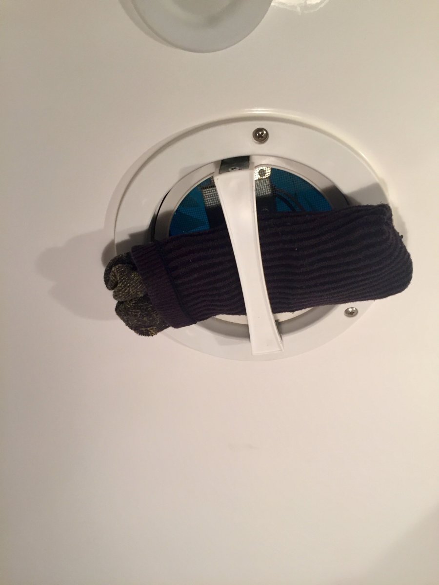
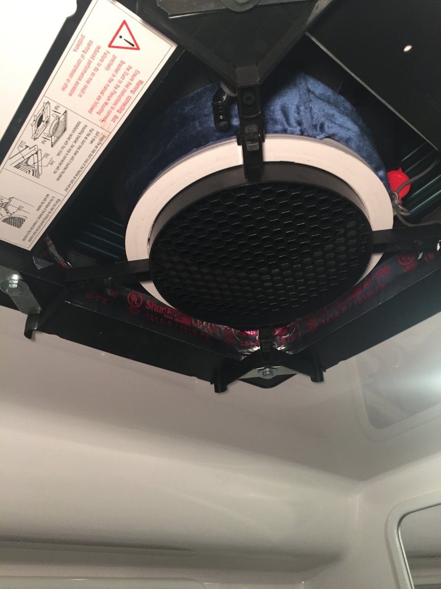
I noticed this happening on our last trip. My temporary fix was obviously to stuff a sock in it.
When we were back home I found that the plastic hood was deformed around the screw that mounted it to the inside handle. So this caused a small air gap around the plastic hood where it made contact to the frame. This resulted in wind getting underneath and lifting it open. The remedy was to use a heat gun and warm the plastic around the screw hole and then form it flat again. Once the plastic cooled off it stayed flat. I then added a flat piece of stainless steel as a back up plate. I did use some silicone sealant between the hood and the plate. So far it has cured the problem.
-
2
-
5
-
-
Carl
I have the Honda 2200 with propane conversion and has no problem starting AC from eco mode running from ether fuel source. Wish you good luck with your project. Happy to answer any question you might have.
Paul
-
Ocala Guy
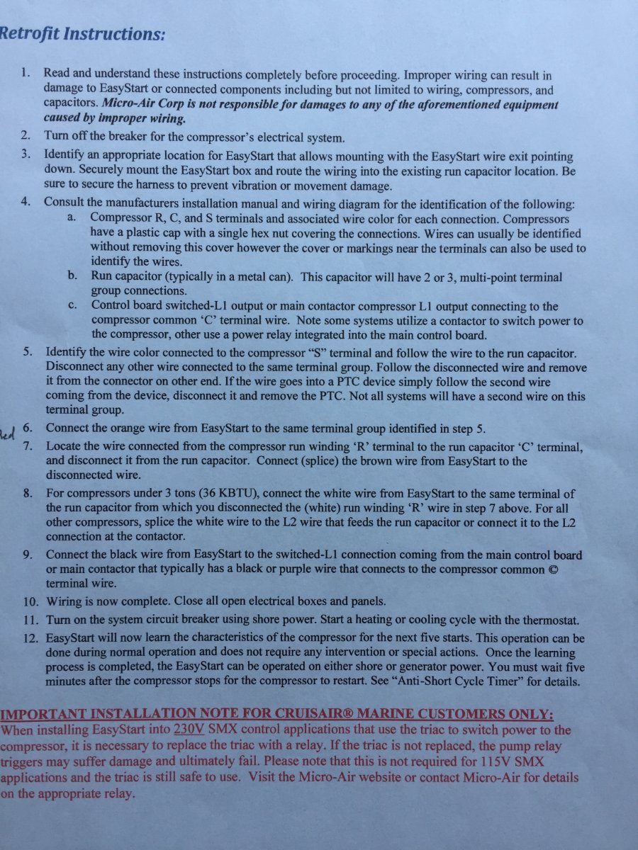
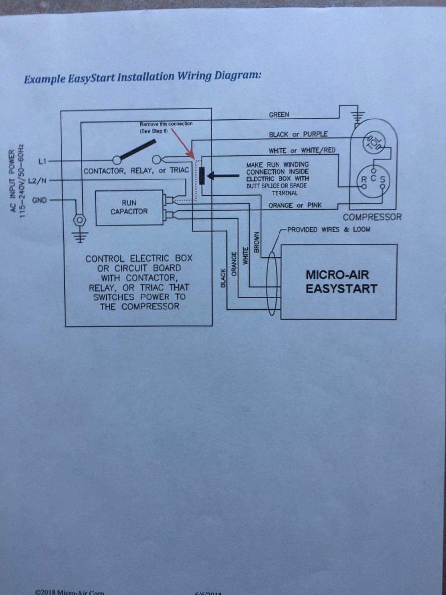
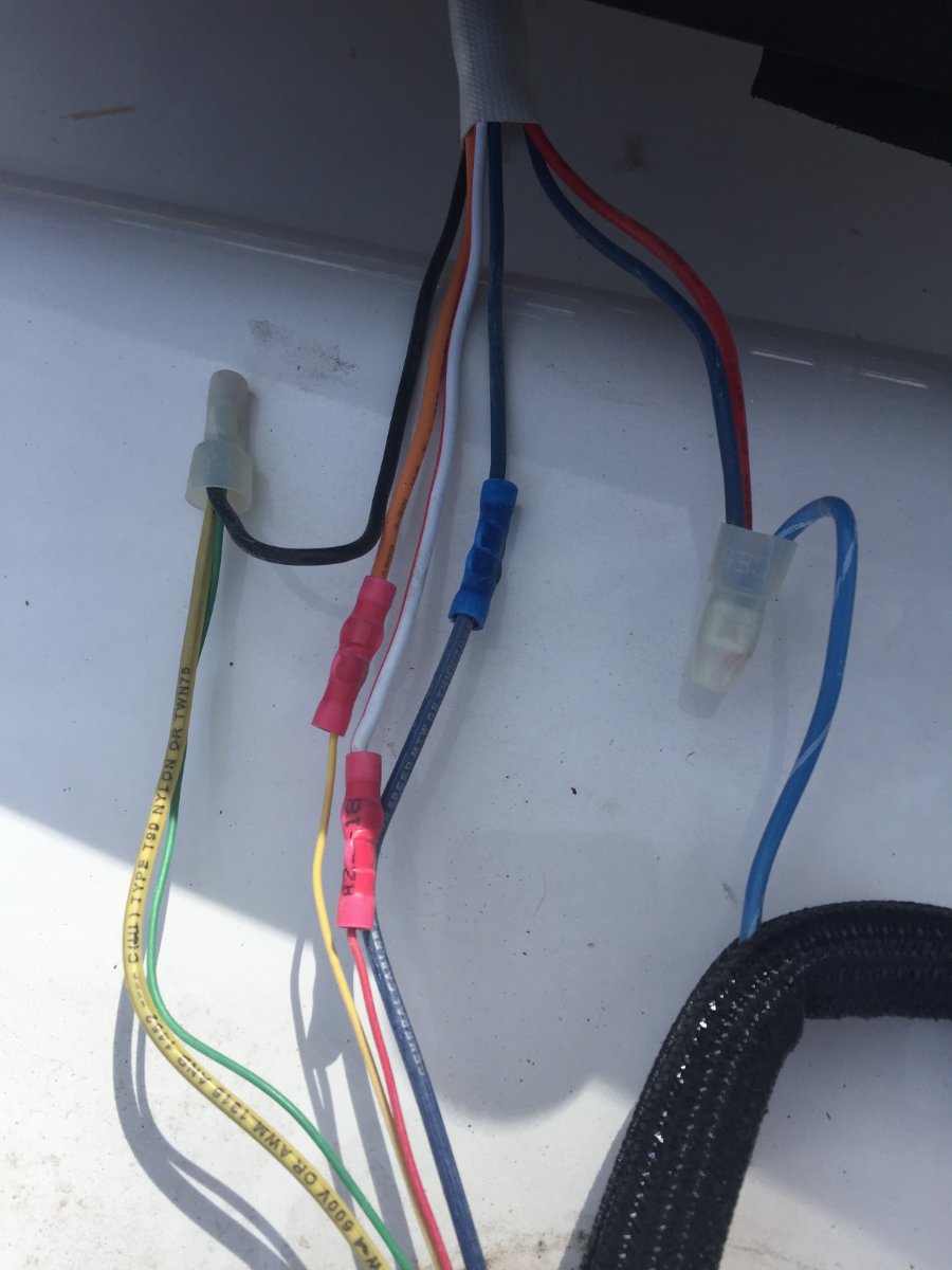
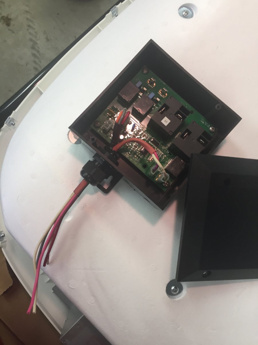
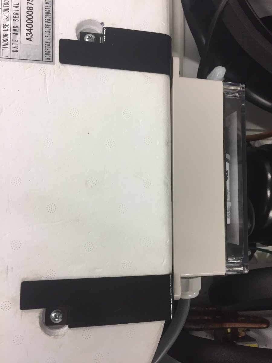
If you go to Micro Air Easy start website, they have resources on how to install their product plus specific schematic for the Houghton AC. Print them off for reference when installing. Under the hood of the Houghton space is limited, you can't see from the pictures but there are two electrical boxes, one on each side of the insulated portion of the AC. Looking at the pictures, the enclosure that has the lead wire from the Micro Air soft start going to it contains the capacitor you will need to connect to. You will also have to run wire to the other enclosure to connect the black wire from Easy Start to the switched-L-1 connects coming from the main control board or main contactor that connects to the compressor common terminal wire. I chose to make a shorter wire run directly to compressor just in front of the over load protection devise.
For mounting the Micro Air I used Velcro but added two straps made from banding to help support it since it was hook to Styrofoam.
Paul
-
2
-
1
-
-
I thought I would call Battle Born Batteries and ask them about this issue with camping in hot temps. First I looked at their website and found this information.
Temperature restrictions on Battle Born Batteries
Battle Born Batteries protect themselves from charging in cold temperatures and won’t accept a charge once the internal cell temperature drops to 24°F. At this point they will continue to discharge even down to -4°F. At this temperature we recommend no longer pulling power to avoid damaging the batteries.
Insulated battery boxes, heating blankets, and placing your battery bank inside your RV will help keep the temperature stable. On the high end of temperature range, the batteries will shut down once 135°F is reached.
When talking to the representative he advised me that I would see a slight loss of performance in 105 and plus degrees battery temperature but it would not hurt your battery and it would retain it normal performance once you were in cooler climate and battery temp drop below 105 degrees, also the battery will shut down once 135 degrees is reached in the battery. He said that it has not been a problem with RV users.
I think in the case of the Oliver with it's battery not in the direct sunlight I don't think they'll be a problem. I would suggest anyone trying to make a decision on what battery type to buy should contact the battery manufacture and get all of their concerns answered. I know at Battle Born the rep was very knowledgeable and friendly and would probably talk to you all day.
Paul
-
2
-
3
-
-
On 4/9/2021 at 3:37 PM, Minnesota Oli said:
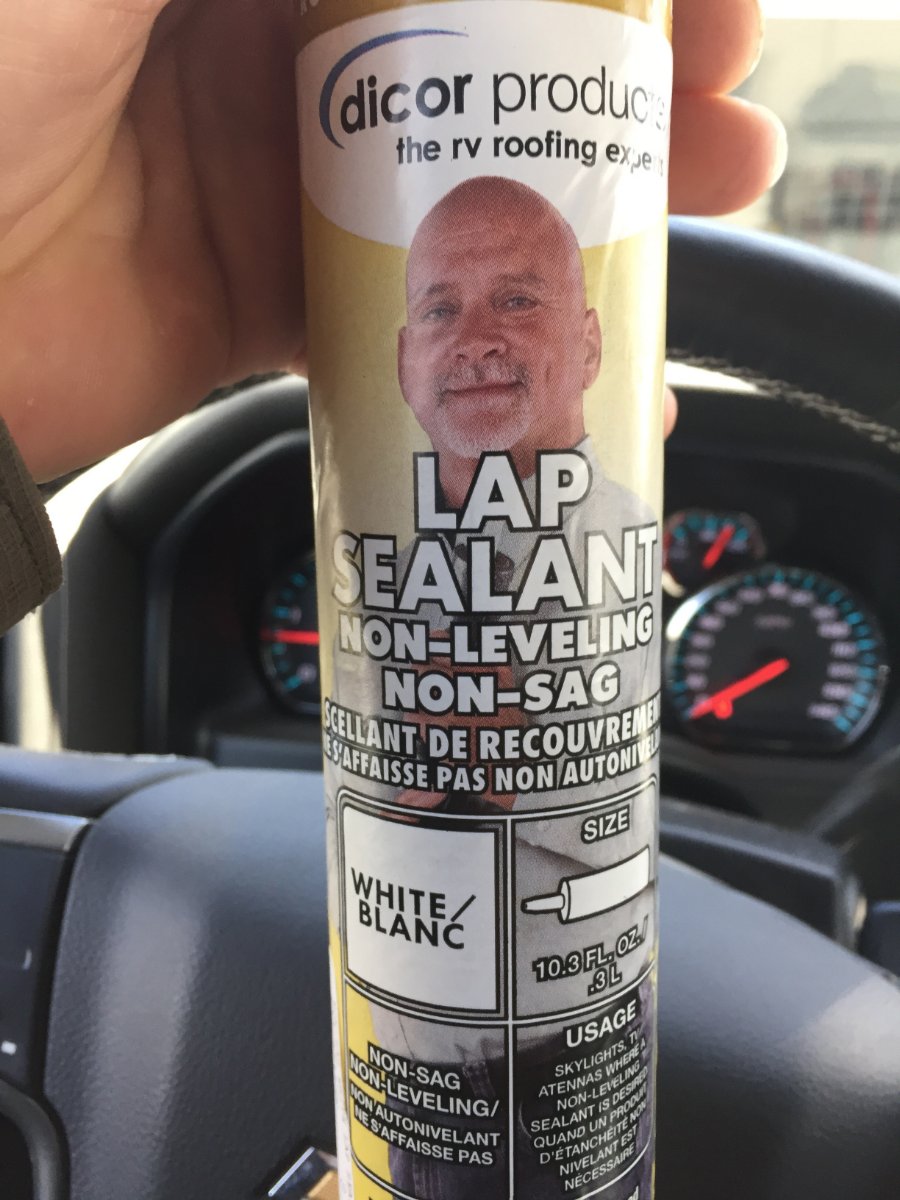
I will chime in because I went with Dicor lap sealant non leveling. I applied it to the under side of the outside mount frame and put it in the opening with four bolts in place. Then I put the inside mount frame in place and hand tightened the nuts with very little force. This assured me the all was lined up properly. I smooth out what squeezed out by dipping my finger in water and forming a bead around the frame. I let this sit for 24 hours before installing the ac. When I torqued the bolt to 9 ft lbs I looked up on top and saw a couple spots where my formed bead had some small bulges but I'm satisfied that I have a good seal. When time permits I'm planing to write up my version of this AC install.
My version of Houghton AC install.
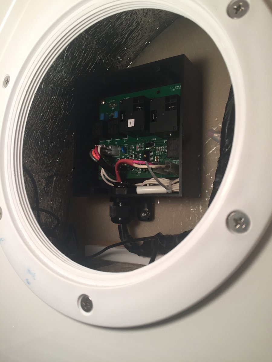
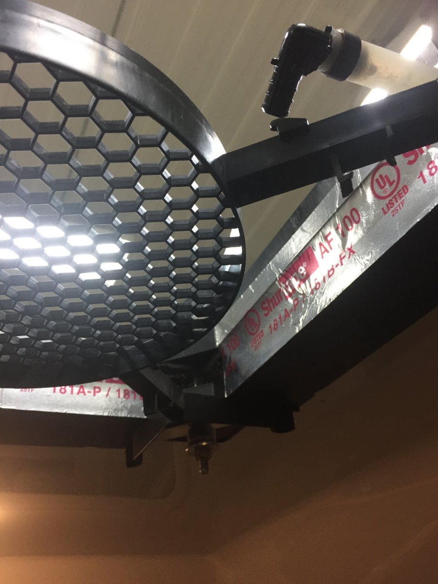
Start out by cutting 120 volt power to AC and 12 volt power to furnace. Next remove the plenum of the Dometic Penguin II on the inside of the Oliver. This will expose a group of wires that are in a black sheath, these are the control side of the wiring for the AC. These go to a LCD relay board that controls Cool/Furnace/Heat Strip that is mounted up in the AC. You will also see a metal electrical 4" x 2" Handy Box that will have the 120 volt power supply for the AC. Both sets of wires can then be disconnected and the four bolts holding the AC on can be removed, this allows you to remove the AC from the roof of Oliver.
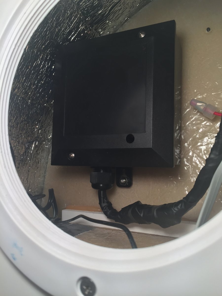
The Houghton AC will not be using the Dometic thermostat that's mounted on the wall because it comes with a remote but your furnace still needs the wall thermostat which works with the LCD Relay Board. I wanted to preserve my old AC with the LCD relay board intact for resale, so I purchased a replacement board mounted it in a plastic box. I installed it in the area where my tank monitor is with the access through pantry.
Where I disconnected the control side of the wiring harness from the AC I then connected wires long enough to be routed back to the new LCD relay board that is mounted next to the pantry.
I then connected those wires to the relay board. One other item is the relay board has a freeze sensor that needs to be hook up or you will get a error message. That sensor is mounted in the cooling fins on the AC, so I had a temp sensor left over from a refrigerator repair I did a while back and that worked as a replacement.
The Houghton comes with a roof mount frame, this gets a sealant applied to the under side of it and that is set in the opening in the roof, I used Dicor Lap Sealant. The roof has a slight radius built in to it to help shed water so the flat roof mount frame will tend to teeter in the opening. I applied the sealant to the under side of the outside mount frame and put it in the opening with four bolts in place. Then I put the inside mount frame in place and hand tightened the nuts with very little force. This assured me the all was lined up properly. I smooth out what squeezed out by dipping my finger in water and forming a bead around the frame. I let this sit for 24 hours before installing the ac. When I torqued the bolt to 9 ft lbs I looked up on top and saw a couple spots where my formed bead had some small bulges but I'm satisfied that I have a good seal.
I made the 120 volt connection to the AC with waterproof connectors and discarded 4" x 2" Handy Box so I would have less obstructions in the air passageways. I also used aluminum foil tape to smooth the transition between the two mount frames.
As a sidenote halfway through the install I thought of a different way of doing the wiring for the thermostat. If a person replaced the LCD thermostat with a older manual style you could do away with the LCD relay board. If you look at the first picture that shows a group of wires that are in a black sheath, these are the control side of the wiring for the AC. In that group of wires there are two blue wires one with a white stripe. The one with the white stripe is hot 12 volts DC and the solid blue is the wire that goes to the furnace relay board. So re-allocate the existing thermostat wires by doubling them up ,two of them hooked to the solid blue and the other two hook to the blue with the white stripe. Then at the wall hook the two thermostat wires that are hooked to blue with white stripe to the power in on the new manual thermostat and the other two to the power out. The reason I would double them up is because of they're small gauge. This would do away with having to pull wires and using the LCD relay board. Also save you having to toggle through the unusable modes (heat strip, cool) on the LCD thermostat to get to the furnace mode.
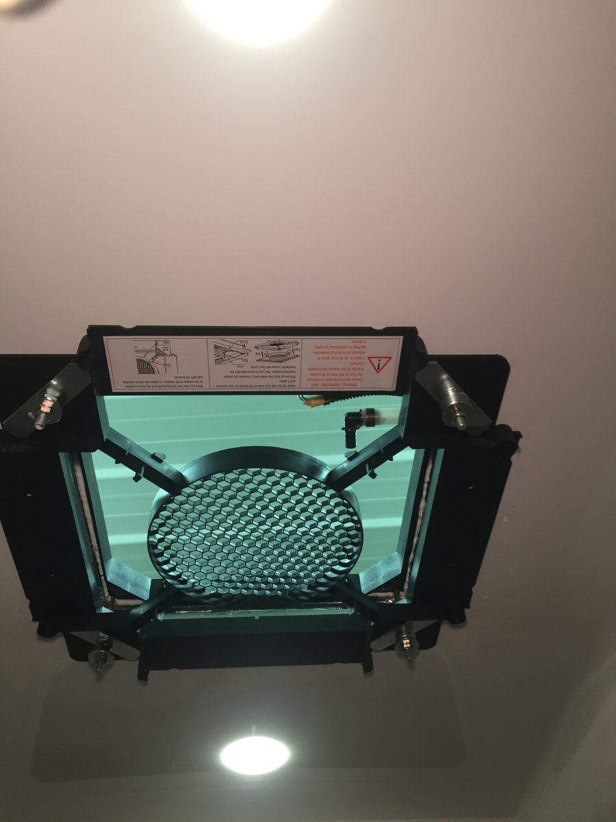
I am very pleased with the sound levels of this AC, you can easily have a conversation between two people without any difficulty of hearing each other. Plus it also has heat mode and dry mode.
I should have done this write up sooner when it was fresh in my mind. Oh well.
Paul
PS I also installed the Micro Air EasyStart. I wanted to ensure that my Honda 2200 would be able to start the AC from eco- mode. You can see from the pictures it was very tight space to mount the unit.
The captured inrush amps before installation was 67.1 and 48.9 after install.
-
5
-
2
-
-
13 minutes ago, River Rat said:
Hey Minnesota Oli, thanks for this!
You mean to say I don't NEED to change my inverter? Somehow I presumed i had to go w/ pure sine wave when converting.... can't explain the rationale that made me arrive at this conclusion, but this is, indeed, great news for my dusty wallet:)
@SeaDawg, these poor AGMs are badly swolen, and no longer keep a charge for >15 minutes or so. Yikes!
I have all the stock charge controllers, the Zamp ZS-30A solar charger does have as selectable battery type on the display panel with LiFePO4 as a option. Battle Born did advised me to disconnect the temperature probe from the Zamp solar controller. The Progressive Dynamics Power Center charger has a selectable jumper on the board that needs to be put LiFePO4. The stock inverter only takes DC and converts to AC nothing to do with charging.
Paul
-
I have upgraded to 4) 100AH Battleborn, and also added Victron Smart shunt. I kept all other factory installed charging components only switching them to LiFePo.
We had spent the last two weeks of April in Utah and Colorado with out ever being hooked up to shore power. We had to use the furnace every night and used inverter for coffee pot every morning and some use of microwave. I was happy to see that my batteries were always at 100 percent after a short time of solar charge. So at this point I am not planing on up grading my charging components, time will tell.
-
2
-
-
Here's a link to Dicor web site.
https://dicorproducts.com/product/non-leveling-lap-sealants/
-
I will chime in because I went with Dicor lap sealant non leveling. I applied it to the under side of the outside mount frame and put it in the opening with four bolts in place. Then I put the inside mount frame in place and hand tightened the nuts with very little force. This assured me the all was lined up properly. I smooth out what squeezed out by dipping my finger in water and forming a bead around the frame. I let this sit for 24 hours before installing the ac. When I torqued the bolt to 9 ft lbs I looked up on top and saw a couple spots where my formed bead had some small bulges but I'm satisfied that I have a good seal. When time permits I'm planing to write up my version of this AC install.
-
1
-
2
-
-
2 hours ago, NCeagle said:
And my .01 cents (only half as good as what katanapilot has done)...
I did something similar to what katanapilot did but I was a bit more lazy. 🙂 I removed the 120V connections from inside the relay box as that's mandatory to connect to the new Houghton. Once those connections are gone it is easy to remove the board as katanapilot did. This is where I got lazy - rather than remove the compressor relay, trim the board and fit it into a custom box, I just wrapped the board in a non-conductive plastic bubble wrap bag and secured it up in a void in the new AC unit. Maybe I'll do it right and do the extra work that katanapilot did one day - especially if my board fries in the bag. 😬 "Right" for me would be not having that board in the Houghton at all - I'd just put a new board near the furnace and run a new set of wires.
I don't have the E5 error like katanapilot. My freeze sensor is connected directly to my thermostat apparently as the sensor and wire come out of the wire bundle - not the relay. So I suspect mine was set up slightly differently than katanapilot's but not sure. I just rolled up the wire and stuffed it back into the roof with the thermostat sensor intact. No issues yet.
Minnesota Oli, definitely looking forward to a report back on your install after seeing the amazing work you did on the street side heat duct!
I really value the feedback from both you and Katanapilot, this will be my first experience with RV furnaces , AC's and thermostats. Looking forward to the project and learning the ins and outs of it.
Thanks Again
Paul
-
2 hours ago, katanapilot said:
I'll offer my two cents as to how I modified the relay board and box. I removed the AC power lines from the box and reused the quick connect wire connectors from the Ollie's romex wire to the new Houghton AC lines. I would normally use wire nuts or similar, but I assume OTT has had good results with the quick connectors and if they become problematic - they are easy to change. I opened up the Dometic relay box and removed the board from the box. I removed the large AC relay (that controlled the compressor on the Dometic A/C) as described in a earlier post. I trimmed a couple of corners on the relay board using the pencil grinder and cut slots in the new box for the DC wire connections to/from the thermostat and furnace. I put the cover on the new box, connected the thermostat and furnace wires and attached high strength velcro to the box. This smaller box fit nicely up in the void in the plenum (picture provided earlier). I did not save the freeze sensor from the Dometic A/C as the only use for it would be to prevent the "E5" error code that shows up when the Dometic thermostat is powered up. It doesn't bother me and it doesn't affect the functionality of the thermostat in furnace mode.
Sorry I didn't take a bunch of pictures.
Hey thanks for the reply. I received my Houghton AC last week and now have time to do the install. I appreciate you sharing your research and solution to the noisy Dometic , I think the hard interior of the Oliver makes it worse. I have been following this topic and see that several other owners have made the improvement but have not mentioned anything of this issue of Dometic thermostat requiring Dometic AC for the Dometic furnace to function. Then my Oliver is a 2019 and maybe theirs is set up with different equipment. Well thanks again, I can now move forward with the install now that I have a better understanding of what I dealing with.
Paul
-
If I understand correctly you have to pull the control board from the AC and mount it somewhere in the opening so you can still use the furnace through the existing thermostat. If that is right could you describe the process.
-
Could you convert the files to standard JPEG? Would love to see your project!
-
I received this from a friend who lives in Nevada. Struck my fun bone thought you all might enjoy.
-
 4
4
-
 1
1
-


.jpg.abf6c21f021b036ef41968cc19b9f78a.jpg)


Battle Born Lithium Ion 12 Volt Batteries in an Oliver?
in Mechanical & Technical Tips
Posted
Yes they fit very nicely.