GSMBear
Members-
Posts
30 -
Joined
-
Last visited
Everything posted by GSMBear
-
RecPro Houghton Interior Fan Mod v2.pdf
-
It's been a year since mine was out-of-the-box new and installed but it does sound familiar to the time when I did not have the compressor fan relay mod and relocated indoor temperature sensor in the equation. I just used mine this weekend (it's in an Airstream, not an Oliver) parked in full sun and low 90s for the highs. When set to auto, my fan will come on high for a short while and then taper down to low as it gets cooler inside. During the hot part of the day, it would run on low for quite a while (an hour?) which was fine with me. It's very quiet and it kept the inside temperature at a comfortable 74 degrees which was the set point. At night, I like it cooler. I would set it to 70 degrees and it would maintain that. On cycles during the night were frequent and short. I don't know what the interior humidity was because I've stopped measuring it as that problem seems to be solved. My application is different from yours, though. I do not have the timer mod installed in mine but I do have the fan relay mod. Moving the indoor temperature sensor was a pretty easy task with my RV but might be significantly more difficult in the Olivers and Casitas.
-
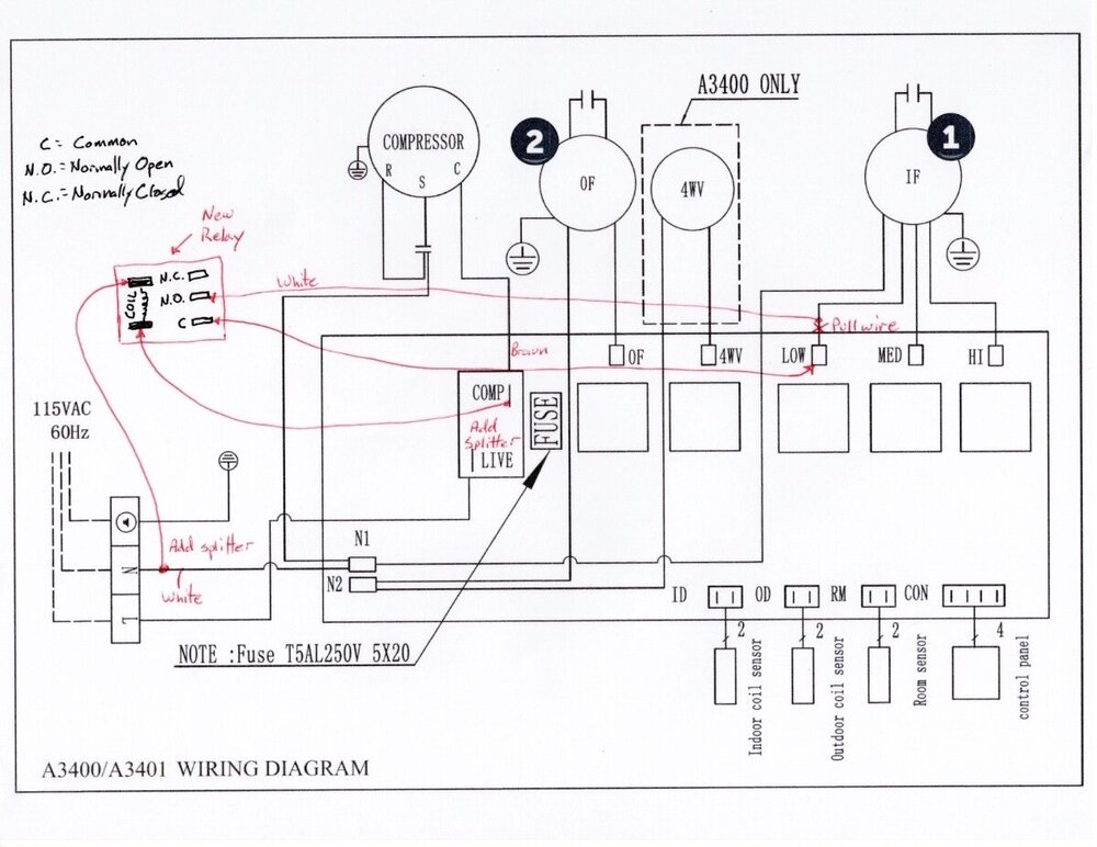
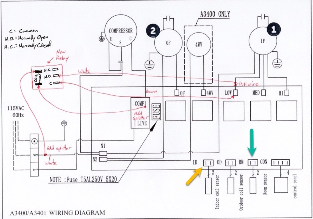
I apologize for unintentionally creating confusion. The schematic diagram posted above was meant to illustrate the ports for the coil sensors. It also has the conceptualized wiring plan for the new relay. The conceptualized plan was drawn prior to knowing what my wire color choices were going to be limited to based on my wire supply. Please ignore the wire color labels in that diagram. To be more precise about your question though. . . When you open the cover to this control box, you will see the thin white wire from the factory connected to the low fan speed blade. You want to remove it from that blade and reattach it to the COM blade on the new relay. Then, take a section of your own wire that you'll need to supply (about 10") and connect one end to the low fan speed blade and the other end to the Normally Open (NO) blade of the new relay. In the pictures from the v2 PDF document, both of these wires are white with the new wire that I had to supply being the thicker wire. Hope this helps and I apologize for creating the confusion.
-
The A3400 has separate sensors for the room temperature (the one I relocated), indoor coil, and outdoor coil. The room sensor is not used for detecting coil freeze-up. In my particular application, it was easy to disconnect the factory sensor from the main board and attach an auxiliary sensor with a much longer cable and route it to the location of the RV's original thermostat. This won't be the case in every application and I think your timer solution is a very valuable addition to the knowledge base with the non-desert applications of this otherwise fantastic AC unit. It's been in the upper 80's and low 90's in East Tennessee this week and I've been running the AC with a setting of 74 degrees. I keep the RV stored on my property where it is connected to power and internet. I've been monitoring the temperatures in the front and rear sections and it remains within less than a degree of the set point. My RV is 23' with no slides and was originally equipped with a 13.5K unit -- it is not an Oliver RV. EDIT: please ignore the wire color descriptions in the schematic below. The schematic is attached to show the connection points for the coil sensors.
-
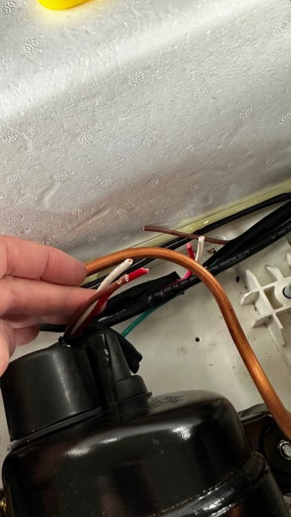
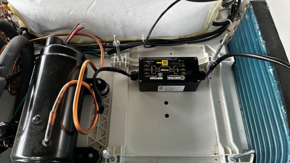
Yesterday, I installed a Spartan Power Soft Start in my RecPro/Houghton A3400 air conditioner. It's identical to the one RecPro sells and is $100 cheaper on Amazon at https://a.co/d/cvYZV39. The wiring method on this one is different from other popular models. I've done both now and this one is much simpler. I removed the fan and found a place mostly out of the way underneath it on a flat surface. All you have to do is use your finger to trace the wrapped set of wires coming out of the compressor to a point where you can cut them. There will be 3 wires: red, white, brown. After snipping the wires, the 3 that are still connected to the compressor get connected to the "compressor" side of the Soft Start. The 3 remaining wires on the other side of the snip location get wired to the "supply" side of the Soft Start. Red-to-Red, Blue-to-White, and Black-to-Brown. Button it up and let it run for 30 minutes with the temperature set close to the interior temp so that it will cycle on/off a few times. Then good to go! I had no trouble when mine cycled on while the microwave was running. The combination of these two puts me near my limit of 30 amps so it will depend on what else might be running. The refrigerator was off and if it had been running, that might have put me over the limit. It's a balancing act, for sure. The picture with my fingers shows the snipped wires that lead back to the compressor. The other end of the same snipped wires represent the "supply" side. The other picture shows the mounting location which is accessed by removing the 4 nuts that secure the large black fan. Clean the surface with some rubbing alcohol first then peel the double stick tape and press it down.
-
FORD SUPER DUTY TRAILER MOUNTED CAMERA
GSMBear replied to Wandering Sagebrush's topic in General Discussion
I'm also interested in this. I believe there is something similar for the F150. And I'm wondering if a lower mounting location -- such as license plate level -- would still offer good multi-views on the dash display. -
I kind soul over on the AirForums has brought to my attention a discrepancy in the original PDF document I shared about the fan mod that I did on the RecPro/Houghton AC unit. Steps 5 & 6 are correct when viewing the pictures but the narrative I added was incorrect. I've updated the narrative and I will try to post the v2 document here. RecPro Houghton Interior Fan Mod v2.pdf
-
This is the one that I used: https://a.co/d/ceHt1sT. That's a suspicious looking link but I guess that's how Amazon creates them so that they're short. I followed the link and it does go to the correct place. Or search for this item in the picture.
-
I was browsing the RecPro website the other day and noticed a new addition to their Quiet AC lineup. They now have an AC/Heat pump model with a condensate pump for retrofit installations that have existing drain management to whisk away the condensation. Unfortunately for Oliver owners, the 15K size of the unit is probably too much for the space. It is also their higher profile unit which might not be appealing to some. Perhaps it will be an expanded offering someday in their low profile units.
-
Ah, I see. Very clever how the former wires were put to good use. But as a former co-worker used to say: "Your problem is very clear to me." Unfortunately, I'm coming up short on solutions. But tinkering and just sitting in the space and thoughtfully observing - and then repeating as necessary - is likely what lead me to find a solution that worked my situation. When you ask about intercepting the drain tube in the basement area, are you saying this would require cutting out a section of the fiberglass skin to (hopefully) find the tube located behind it? Akin to cutting away drywall to find a pipe or wire inside the wall? I can understand your concern about that, if so.
-
John -- having another thought. . . Your Houghton is a replacement to an original Dometic, right? Is there still an RJ-45 cable that runs from the air distribution box location to the location of your original thermostat? If so, might that wire be the ticket to relocating the thermistor? If I recall correctly, that's not exactly a phone wire. Can't recall where I read it but I think the gist of the message was that two of the wires have their positions swapped from one end to the other which makes it different from a phone wire. The wires are color coded so that should be enough to identify which ones (there are 4, I believe?) are being used to extend the thermistor. And I don't think the concept of polarity is involved -- meaning, I don't think it matters which wire gets connected to the two on the other end.
-
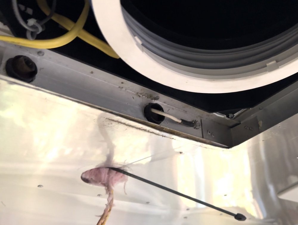
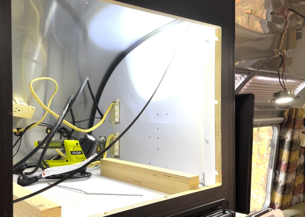
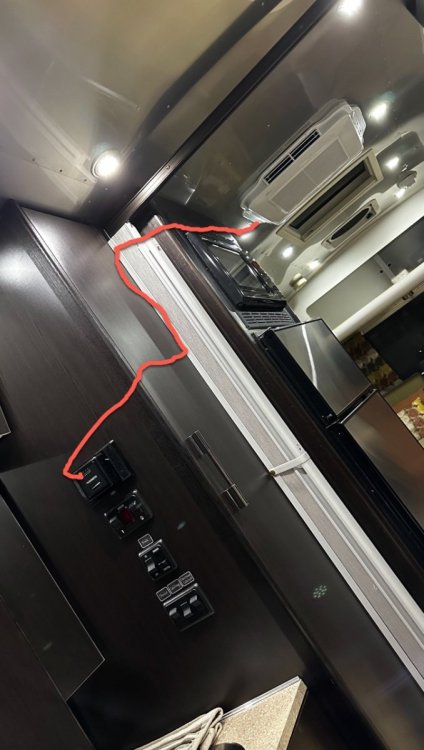
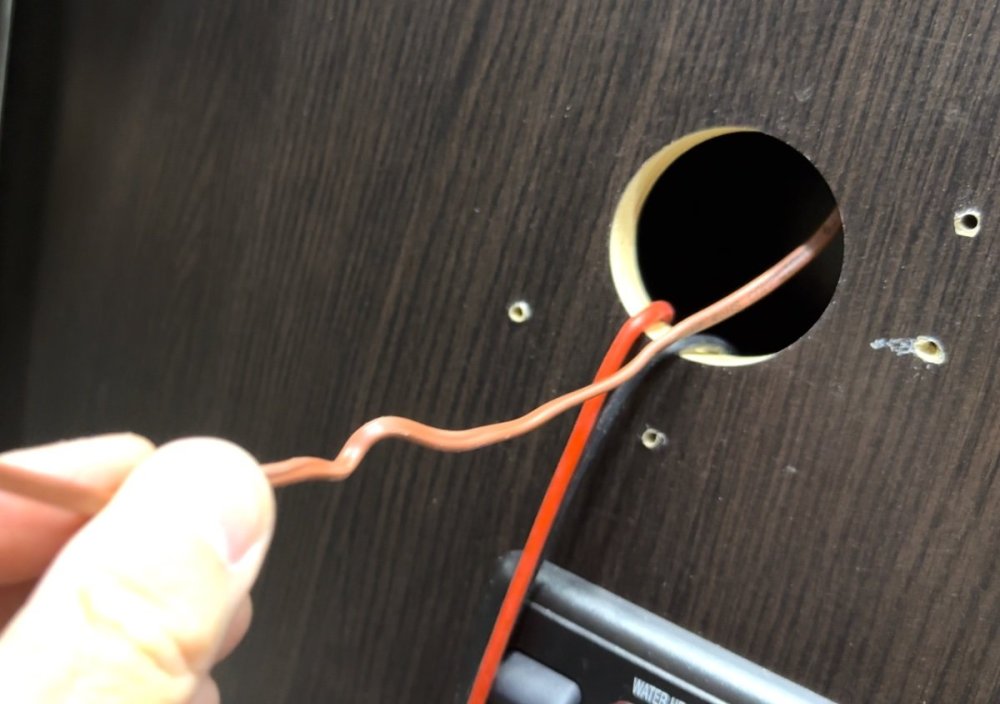
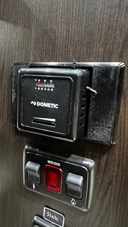
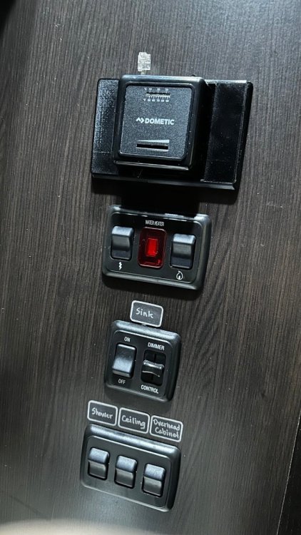
Great minds think alike? 🤔 What I did ended up being similar to this. The final location where I wanted the thermistor provided some good shielding from airflow. It's also at a more reasonable vertical level. My initial testing had the thermistor pretty close to the ceiling because that's as far as the original wire would reach and still get it around the corner of the cabinet. I took a big gasp and snipped the end of the thermistor wire about 8 inches from the tip. Then I added several feet of supplemental wire to extend the length so that it would reach where I wanted it to go. I tucked it behind the cover of the ugly mechanical thermostat that now controls the gas furnace. At first I had it poking out the other side so I wouldn't see it but that appeared to provide too much shielding. I switched it to the side you see in the picture and it seems to have the perfect balance. The short cycling stopped. I didn't time it but I'd say the on cycle was about 10 minutes and felt very comparable to the original Dometic unit. The off cycle was a little longer. Two wifi-enabled temperature sensors provided temperatures of 68.5 at the front by the panoramic windows (in the airflow path) and 70 directly on top of the mechanical thermostat where the sensor is (shielded). I probably had this kind of temperature difference with the original AC but I never measured it. It was too warm to test the heat but I'll get that done later. (If our theories are correct, those fins still would have had a lot of moisture on them.) Pictures below show the path the thermistor wire took: 1) from a factory wire access hole to a nearby ceiling puck light, then 2) across to the top of the interior of the microwave cabinet, then 3) down the side of a closet and under a shelf and through an existing wire access hole for closet lighting to 4) the ridiculously large and off-center hole from the Dometic CCC2 to 5) the final location! In the first picture you can see the snipped drain tube from the Dometic in the top left corner. In my Airstream, this runs directly down the side of the wall and it exits in the street-side wheel well. Would have been nice to integrate this somehow with the Houghton. I'm not sure how this is different in an Oliver RV so I've not commented on your question about this. I'm not understanding how this might provide a path for the wire but I'm sure it's because of my lack of familiarity with your setup.
-
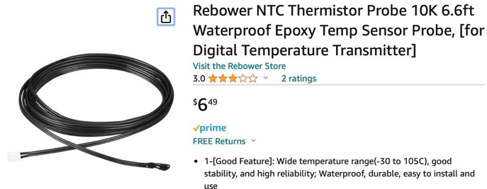
Good News! I am happy to report that the auxiliary thermistor I bought from Amazon works as a replacement to the factory thermistor. These two things are critical to the success: locate the new thermistor away from the air distribution box and away from the airflow. For me, this will be around the corner of a cabinet and likely in the same location as the original Dometic CCC2 thermostat that controlled the original Dometic AC and gas furnace. I tried multiple experiments with the thermistor in the same area as the air distribution box with varying degrees of shielding from the airflow. But it just wasn’t good enough to suit me. This would have been the simpler solution and I wanted to rule it out before moving on to something more involved. I think there’s just too much air movement everywhere around the distribution box and it tricks the thermistor into thinking it’s a different temperature than it really is. The test that pleased me the most was when I stretched the cord out as long as it would go and I taped it in a location near where I hope to set it permanently. The cord isn’t long enough to get me there right now. But when taped to the wall around the corner from the airflow the AC set temperature of 70 was reached and three other temperature devices in the RV measured between 70 and 72 in different locations. The on/off cycles were fairly short which concerns me a little bit and I’m hoping this will improve when I have the thermistor in the final location which will be more shielded from airflow and at a more reasonable vertical location. In heat mode this morning, there was a greater difference between the set temperature of 66 and the actual temperature of 72. Cycles were short and I think if I had let it continue the interior temperature would have gone higher than 72. Perhaps this will also even out more once the thermistor is not as close to the ceiling. I’m less concerned about an accurate reading with heat than I am with AC. I use the RV more in the warmer seasons than I do in the cooler ones. Also, when I turned on the heat this morning, there was a great deal of humidity pumped into the living space. The windows fogged and the moisture on the interior aluminum skin (this is an Airstream instead of an Oliver) was visible. I was surprised to see this and I wondered if it was due to residual moisture still on the evaporator fins from the prior day’s AC testing. Overall, I’m pleased with the testing knowing that I can relocate the thermistor elsewhere and get reasonably good results. If I have to adjust the settings to reflect the differences between set temperatures and actual temperatures I’ll learn that over time and adjust. I feel like the two major wins in this obsession of mine are: 1) getting the additional relay installed to allow the interior fan to cycle with the compressor (solves humidity issue with AC), and 2) finding an easy path to get an auxiliary thermistor from the rooftop control board location to the interior sealed area without much effort. For those interested, this is the thermistor I am using right now. It has the two-pin connector on the end that fits the control board. https://a.co/d/dV31de2
-
Hi John -- that extra wire is the connector to the air distribution panel for the limited control functions offered there instead of from the remote. None of those pins (4, I believe?) involve the thermistor. That wiring clip appears unused in the picture because the air distribution panel has been removed to access the innards. When it's all assembled, there is a corresponding end for that wiring harness on the air distribution panel side. They get connected together upon assembly so that the display panel and controls will work. The "hot poker stick through the Styrofoam" approach wasn't hard and it allows the factory thermistor to remain in place as a backup. I'm going to test the auxiliary thermistor more on Saturday and report back here once that's done. Fingers crossed!
-
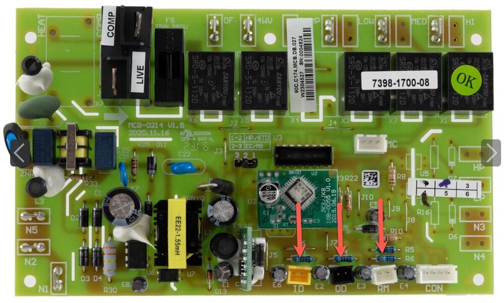
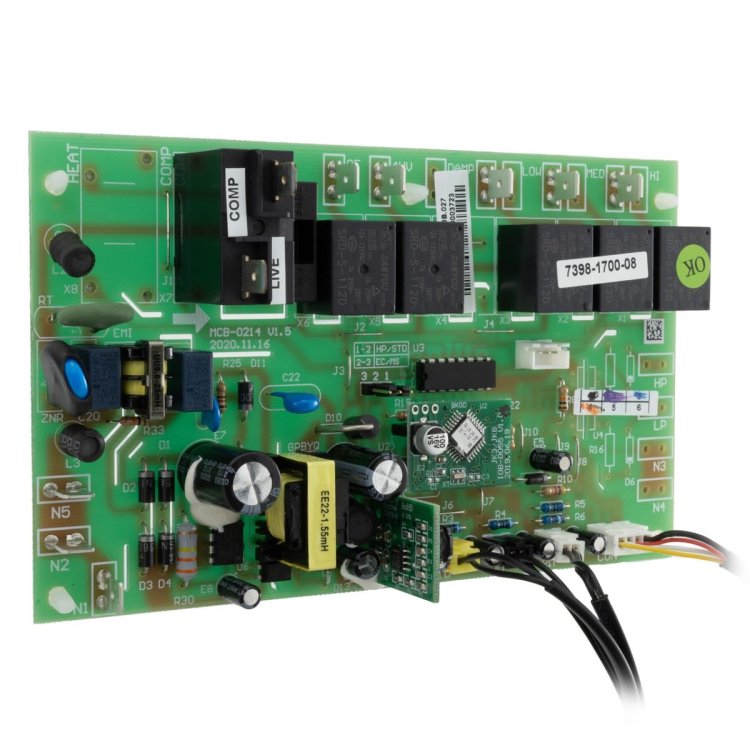
Ah, methinks you're onto something! Your remark about the heat pump not sensing that warmth is being produced made me look at the wiring diagram. I'm now pretty sure that I mistakenly unplugged the interior coil sensor instead of the room sensor. I know it was a yellow connector and the attached picture of the control board positions this one in the location of the interior coil sensor according to the schematic. This adds up! Without the interior coil sensor connected, the fan would continuously wait for the signal that the coils are warm enough to start blowing -- so the fan would never start! OK, so stupid mistake on my part but there's hope left. I will give it another try next weekend and report back.
-
Well, I just couldn’t stand it and had to give it a try. The access method described above worked as expected. The new thermistor, not so much. I’m disappointed, for sure. For testing, I just dangled the new thermistor directly down from the air distribution box which is centrally located in my RV. The thermistor was about waist level. In AC mode, it seemed to be a pretty good solution although I did not spend much time in this mode. The compressor did come on as expected and seemed to turn off much closer to the set point when measured by an external inexpensive indoor/outdoor thermometer at countertop level. In heat mode, the fan would never come on. I could hear the compressor turn on as well as the fan in the rooftop unit, but the interior fan that blows the warm air never came on. Heat was occurring in the coils because when I switched it from heat to fan-only mode, the fan did come on and the residual heat from the heat mode allowed for some warm air to come out. This puzzles me and I can’t help but wonder if the prior fan modification is in the equation somehow. That mod is described upstream in this thread. Prior to the new thermistor, I did notice a change in the fan behavior between AC and Heat modes: In AC mode, the fan cycles with the compressor only when the fan is in Auto mode. It remains on all the time if the fan is switched to medium or high mode (can’t recall about low speed). However, in Heat mode, the fan will cycle with the compressor no matter what speed the fan is set to, including auto. After the new thermistor, the fan would not come on at all no matter what fan setting I used. I returned the setup to what it was before I tinkered with it today and it’s back to running as expected in both AC and Heat modes. HVAC and resistors are by no means my area of expertise. I’d be interested to hear from those who know more on these subjects. For the record, the replacement thermistor I bought is a 10K NTC thermistor. That means absolutely nothing to me but there are gobs of these on Amazon with this specification and advertised as being suitable for mini-split systems which do both AC and heat. So I figured I’d start there. I can’t find any specs on the one Houghton uses.
-
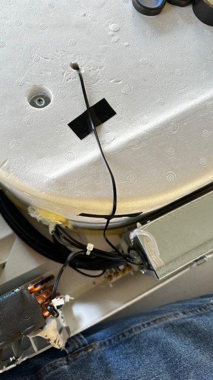
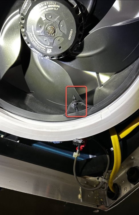
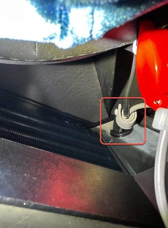
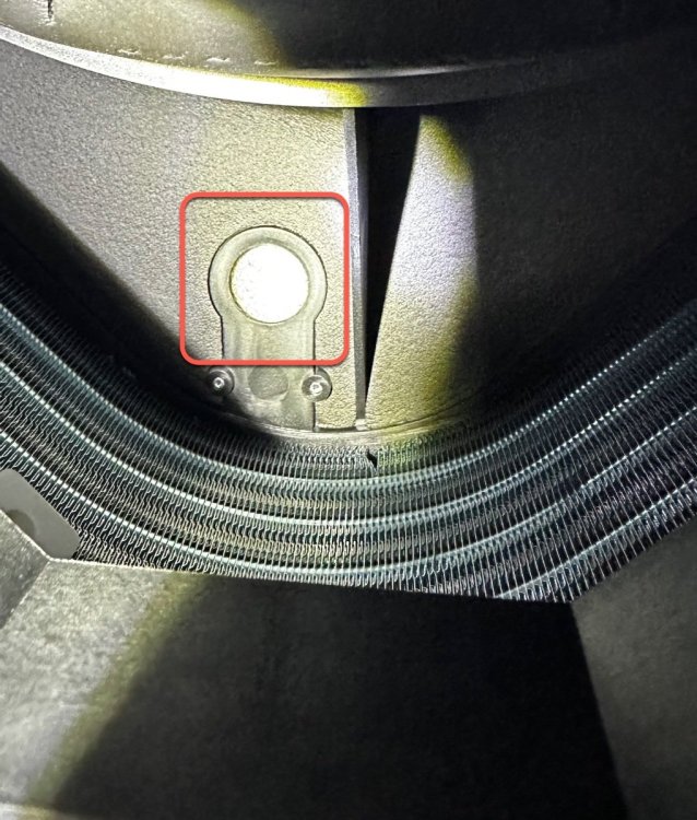
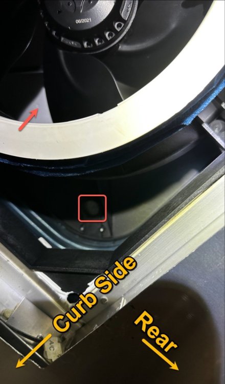
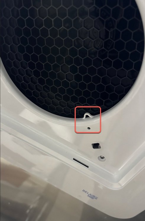
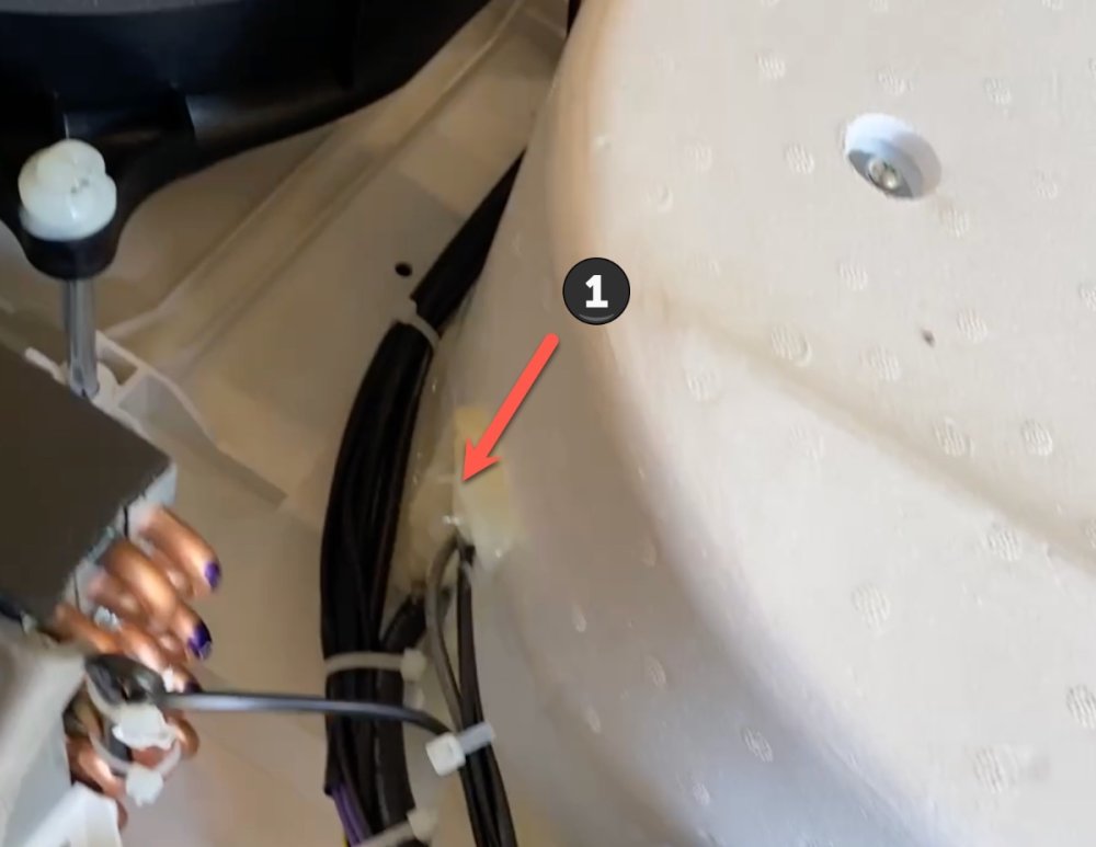
Yes, the continuing saga of finding a way to add and relocate the temperature sensor to the Houghton/RecPro A3400 AC/Heat Pump. Some backstory: with engineering assistance from my brother, we added a relay to the interior fan so that it cycles with the compressor. This made a substantial improvement in the interior humidity issue while in AC mode with the manufacturer’s design. In fact, I’d say it eliminated the problem. But this solution introduced a new problem: Since cabin air isn’t constantly flowing over the temperature sensor mounted in the round return air chamber, there is an increased disparity in real cabin temperature versus the temperature observed by the sensor. This prevents a steady and comfortable cabin temperature. Relocating the temperature sensor to an external location away from direct air flow of the distribution box might solve this problem. But finding a path from the rooftop control board location to the interior cabin space has been a problem. And the existing sensor has no apparent slack in the wire as a means of extending it. Nor do I want to cut it. I removed the air distribution box today to examine the situation again and I think I might have found a path from the rooftop control board to the interior sealed area without breaching the seal — at least not much, anyway. The attached pictures, in order, show the (1) current location of the temperature sensor, (2) enter/exit path of the wires from the rooftop section to the interior section. I’m unable to get a wire pushed through this area to the visible area in the rooftop unit. I can get a wire to go a short distance through this area but it hits something and just bunches up. The situation is the same when approaching this from the rooftop side. The new idea is to make use of this thing (3) — whatever it is. I can poke my finger through the white covered hole in the middle. Another inch or two above that is the interior side of the white Styrofoam insulation that seals the interior system from the exterior system. I’m definitely opposed to removing this cover as it appears to be very well sealed by the manufacturer and I don’t want to disturb it. But I’m not too opposed to poking a very small diameter hole in it with a hot coat hanger or something similar. Any air gap around the new wire could be caulked and sealed. Picture (4) is poorly focused but it shows the access point inside the red square while the arrow points to the white Styrofoam box that seals the system. A small access hole melted into the foam straight up from the access point should lead right to the same corner in the rooftop section where the control board is. From there, I’d disconnect the factory sensor and add the new sensor with plenty of cable length. I’d then route the sensor through the attic space of my Airstream RV and out to the original location of the Dometic CCC2 thermostat that is no longer in the equation. (I’m not sure how complicated this part gets with an Oliver.) It might be a while before I actually tackle this. I’m interested in hearing from all y’all about what it is I might be missing though! (And, when I put the air distribution box back together, did I spot (5) the location of the temperature sensor in the version 1 model of this unit which would have placed it closer to the interior cabin air?)
-
Now that some cooler weather is here I have spent some time in the RV with the Houghton/RecPro in heat-pump mode. As a refresher, I added a relay as a modification to cycle the interior fan with the compressor on the low fan speed circuit. This nicely solved the issue of pumping humid air back into the cabin when in AC mode and the compressor turned off. But it introduced a problem (somewhat anticipated) with the unit having about an 8 degree differential for cycling on again when needed. Also, with this modification, the fan would operate as intended by the manufacturer in Medium or High speed since only the Low fan speed was involved with the new relay. In AC mode, this worked as expected. Fast forward to now with the cooler weather and I'm finding the fan cycles with the compressor regardless of the speed selection when in heat-pump mode. I'm not sure why this is the case. I was thinking in heat mode I might like the fan to run continuously to help keep the set temperature and actual cabin temperature more aligned. Fiddled with it some last night and nothing seemed to keep the fan running in heat mode. I now have something new to keep me awake a night. . .
-
I wish I had taken a picture of the area where this work needs to be performed but I didn't. It's really tight quarters. And for that reason, I think the soldering iron will be necessary because the heat gun will spread heat in areas that might damage something nearby. It's worth consideration, for sure, but I think it would be risky.
-
I hear ya! I have my expectations set very low for the mechanical thermostat but it's already purchased with a custom 3D printed backer plate to cover the factory holes from the Dometic CCC2. I will only need to use this when the temps get low enough that I need heat around the holding tanks. Apart from that, I'll use the heat pump or an electric space heater.
-
It's very tempting! And I agree about the best views being out the rear window. I wish my floor plan had been reversed for this very reason. Airstream no longer sells my model (23D but later called 23CB) and I suspect it is because of the narrow 48" fixed bed in the corner. It's a bugger to make, for sure. I lived in it by myself for a little over 2 years while having a house built and didn't go all Jack-Nicholson-The-Shining-Crazy during that time. Adding a 2nd person for that length of time would no doubt have pushed me over the edge. I can also say during that time I was able to confirm what I suspected: the insulation is fantastically awful. From some remarks in this thread, it appears Oliver does a much better job with this. I imagine the Houghton would perform nicely on an Oliver. So tell me. . . do the Olivers that came with factory Dometic ACs operate via a wall thermostat that also controls the gas furnace? My Airstream did and the "brains" of that operation that allowed the furnace, AC/Heat Pump, and thermostat to all play nicely together was in the AC unit -- which is now out of the picture. I'm going full low-tech on my gas furnace solution with an inexpensive 2-wire mechanical thermostat mounted in the same location as the original Dometic CCC2 (comfort control center?) thermostat. I've yet to run that wiring but I don't expect it to be difficult given their respective locations. Just waiting for a nice crisp autumn Saturday morning to do it. I do, however, still have the phone cable that ran from the thermostat location to the 14" roof opening where the AC unit is. That's the wire I have in mind to use and extend/relocate the thermistor for a better ambient reading if the wire gauge is the same or better. Just need to get my brother here with his soldering iron to give it a go. Of course, if/when that happens there will be a full write up to share!
-
On another note. . . In previous posts and also in a PDF "how-to" document I posted, I referenced about a 4 degree temperature swing with the wiring mod to cycle the interior fan with he compressor. My updated experience is this temperature swing has been as much as 8 degrees! I have temperature sensors in 3 different places inside my 23' RV (it's an Airstream, not an Oliver) and they all give different readings. I'm not too surprised by that. Only the one that is somewhat in a path of the air out of the air distribution box on the ceiling gives a reading close to the set-point on the Houghton. I'm also experimenting with setting the fan to Auto only at night. This is the setting that turns the fan off when the compressor is not running. Then, during the day, I'll set the fan on medium which allows it to run all the time as designed by Houghton. I started this approach yesterday and during the day, the interior RH reading was in the upper 50s. I only have sensors to measure RH. I left the fan on medium overnight and woke up to an interior RH reading of 78%. I slept in the house so it wasn't my breathing that added any humidity. I'll continue to monitor it today with the fan on medium and see if the interior RH drops. BTW, I appreciate the engagement here on this topic. I've posted remarks and questions about this on the AirForums and there hasn't been much engagement. I also find myself looking more and more at those nifty Oliver Legacy Elite II's! A lot less tongue weight for my F150 than my comparably sized 23' Airstream. I like the twin bed offering, too. A buddy of mine and I want to hitch up and point ourselves west and "go see America" when we retire -- if my parents' health permits. The two fixed twins would be ideal. But, man, I'd hate to give up my front panoramic windows that I love so much! Conundrum. . .
-
I hear ya! I won't be that brave soul. . . but my brother might! He lives out of state but he loves the Great Smoky Mountains so it's not hard to convince him to visit, when he has time. When he does visit, he stays in the Airstream that is tucked away nicely in its own "AirPort" not far from the house. He's an electrical engineer and is always curious about solving problems like this. He has seen where the thermistor is and knows that soldering new extension wires would be an over-the-head task. But I think he's open to it. Whether we can get all of the necessary hands up into the area to manage the task is yet to be seen.
-
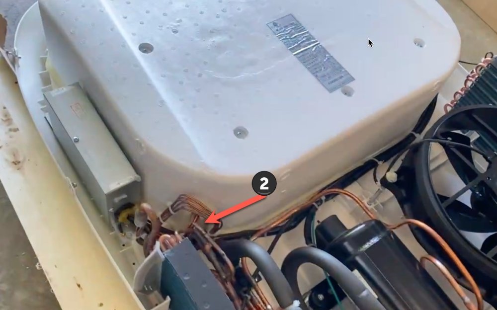
Hi John -- yes, the thermistor wires end up on a 2-pin connector on the control board on the curb side of the rooftop unit. The problem is getting a replacement thermistor wire from the outdoor/exposed area of the rooftop unit into the interior/sealed section that is accessible from inside the RV looking up into the unit after removing the ceiling plenum. In the pictures from the post directly above, the thermistor wire goes from the control board and enters the sealed Styrofoam area at marker #1. However -- and this is the part to really understand -- that thermistor wire does not appear anywhere from inside the RV looking up until it comes out of the area by marker #2. How that wire gets through the sealed area from marker #1 to maker #2 (on the inside) is not clear to me. I think I would have to unseal the Styrofoam section to see and follow that path and I'm not keen on doing that. I already have a new thermistor and I tried feeding it through the entry point at marker #2 and it never showed up inside the RV. Where it went, I don't know. But I'm not convinced that's the path to use. To make matters worse, there appears to be some cable ties (a reflection of a good quality build, IMO) that would prevent me from splicing wire from the outdoor rooftop side (where I have good access and can use a soldering iron easily) and gently pulling it though whatever path it takes. So it's a bit of a pickle, to say the least.
-
Yes, but. . . I have seen the thermistor by looking up into the return air duct after removing the inside plenum. There's a short section of wire that leads to an exit path on the STREET side of the unit. And you would think this would exit into the rooftop section on the STREET side making a replacement a simple task. However, my experience is this: From on top of the roof, the lead wire from the control board enters the protected/sealed area under the Styrofoam on the CURB side of the unit. From there, it appears to travel to the STREET side of the unit in a way that I think can only be accessed by unsealing the Styrofoam and removing it. A task I'm not keen on doing. When I attempted to feed a new thermistor into the access hole on the STREET side of the rooftop unit, it never appeared on the inside when looking up into the return air duct. Where that lead wire went, I have no idea. I'm guessing it got all bunched up on something. (If someone else has done this, I wanna hear from you!) In the attached pictures, marker #1 is the entry path to the sealed area on the CURB side while marker #2 is an entry path on the STREET side. My findings might be wrong, and I hope they are. But I gave up on the task because the unit is new and apart from the roughly 4 degree temperature change for cycling, I have it working well. I'm definitely in agreement with John's remarks about soldering an equivalent gauge wire to the thermistor to extend it. The problem is, without the ability to easily feed the wire from the rooftop section to the interior section (the issue described above), there isn't enough slack wire to get it to an easily workable area with a soldering iron. It's pretty tight quarters up in the return air duct. My brother has some experience with this and I'm planning to wait for a return visit from him to explore it more.


