
RnA
-
Posts
80 -
Joined
-
Last visited
-
Days Won
4
1 Follower

RnA's Achievements
")


-
And then there is the Electric Airstream to go with your electric truck... https://robbreport.com/motors/aviation/airstream-new-electric-trailer-estream-1234659272/ Still, 300 mile range for the Ford truck and the trailer isn't enough.
-
 Thanks John, I was reading that on the Victron reference you provided and the Blue Sky Solar web site as well. They have modified their MPPT controller to take higher input voltages (i.e. panels in series up to a limit) . My comment should be for a PM controller.
 -
For RVs, I don't know of any advantage other than when using long cable runs with portable panels. The higher voltage output lets you use a higher gage wire for the same power transmission. With a portable panel you have the option to move the panels and keep them in the sun. The disadvantage is that when in series, if one of the panels gets shaded your pretty much done for output. MPPT controllers help, but they can only do so much. When the panels are paralleled, shading of one panel will not effect the other panel and you will be down to half power, but at least something. This may not be an issue for some that camp in sites open to the sky however much of my camping has some shade. Sometimes one panel is shaded in the morning while the other panel gets sun and vice versa in the afternoon. With the panels in series, I wouldn't get anything.
-
$150 to $250 off on their 100AH LiFePO4 batteries today if anyone is looking. https://battlebornbatteries.com/product-category/lifepo4-batteries/
-
Is my electric switch for the rear jacks are upside down
RnA replied to Trainman's topic in Mechanical & Technical Tips
Doesn't the inverter power the water heater if the ac switch is on? -
Why not use the Furion 10amp exterior connector straight from the solar panel? Are you planning on going beyond 100watts? If you use that connector could then locate the controller under the aft dinette seat. My setup has wires from the outside Zamp connector direct to the batteries (through a 10amp in-line fuse). You could install the controller between the port and the fuse. When using the extension cord you need to be careful of powering the male plug from either batteries or solar panels. If male is at the panel end with an adapter (with an inline fuse) to the panels I think ( but you need to check on your specific charge controller) the charge controller should have diodes to prevent current flowing back out to the panels (this is done to keep your batteries from discharging back into the panels at night). With the extension cord male end at the other end, you risk damage your panels with an accidental short of the plug. Your idea of using only the ground and neutral is a good one to keep from putting 120 ac into your controller. Just make sure the ground is 10awg also. A Furion connector to male plug would complete the trailer side.
-
agm batteries still have a potential to vent hydrogen, particularly if overcharged. here’s a good link with an explanation of the rvia position: https://rvnerds.com/2017/11/01/electrical-myths-part-4-agm-batteries-dont-need-venting/ “The Recreational Vehicle Industry Association’s Low-Voltage similarly requires venting for all battery locations, whether or not batteries are actually installed, and prohibits installation of other potentially spark-producing equipment in the same compartment (e.g. inverters, charge controllers, disconnect switches):.....” regarding Li, i wouldn’t want any electronics (fire potential) co-located.
-
more simply, the voltage output of the controller is optimized for the battery state. if the controller is at the panels the voltage drop will be more over the long run of wire and less than optimum for the batteries.
-
it will work better with the controller close to the batteries. i would not locate it in the battery compartment though. a pulse type controller will pulse the output to match the the voltage needs of the battery. the duty cycle of the pulses will be driven by the amount of current and voltage on the input. thus as the voltage and the current, drops the frequency of the pulses spread over time. there is probably some minimum input voltage dependent on the specific controller where it all falls off a cliff and the controller won’t output. i think 14.9 volt input would be more than enough though. obtw. an mppt controller will give the voltage output your batteries need but drop the current giving a more constant current flow not pulses of energy to the battery. make sure you fuse the lines. give a try. you can always make cord shorter if need be.
-
50 ft of 10 gage copper wire for 17.7 volt output of the panels, 4.7 amp you'll loose 0.47 volts, 2.65% for 14.3 volt output of the charge controller, 5.8 amp you'll loose 0.58 volts, 4.75% there will also be some minor losses through each of the connections. voltage drop calculator at the link below: https://www.calculator.net/voltage-drop-calculator.html?material=copper&wiresize=3.277&voltage=17.7&phase=dc&noofconductor=1&distance=50&distanceunit=feet&eres=4.7&x=51&y=23 not sure if this calculator is for solid or stranded wire, you should get slightly less drop with stranded as the current tends to flows on the outer surface of the conductor and the stranded has more surface area.
-
One 200 AH lithium battery or two 100 AH?
RnA replied to John E Davies's topic in General Discussion
John, Consider the life time cost of a bank with higher capacity. This will of course be more money in the short term, but the batteries should last longer because they will be discharged less than a smaller bank. As an example; using your battery specification chart above: 400 ah bank discharged to 80% = 320 ah for a life of 2500 cycles Using 320 ah of a 600 ah bank = 53% for life of ~5000 cycles. So by increasing your cost by 50%, you get 100% more life out of your batteries. Either way, that's a lot of cycles. Assuming you got through 5000 cycles, the lifetime cost of three 200 ah batteries would be cheaper than two 200 ah batteries. This is very simplified and I'm sure there are other factors. Something to consider on whatever bank you build, it seems to be better to size for lower depth of discharge. This has certainly been my experience in sizing lead acid banks. -
We used a similar but not as elaborate setup with our previous TV. Two 80 Watt panels on Thule load bars on the truck cap. Since we camp under trees a lot, it was nice to be able to park the truck in the open to recharge. We are looking to do the same with the GMC 2500. We used a 30 gal Valterra tank for water. 8x16x60 size from the tanks at the link below. The tank was rectangular so it took up minimal space at the front of the truck bed. https://www.valterra.com/product-category/rv-products/aftermarket/freshwater-products/fresh-water-tanks/

-
https://nikolamotor.com/badger This looks much better than Cyber Truck. Now teamed with GM who has been working with Honda on fuel cell technology for a while. Fuel cell option seems problematic for refills. Range falls short of the 2500 Duramax for towing. Would be nice if the trailer could be charged off the fuel cell though. - Randy
-
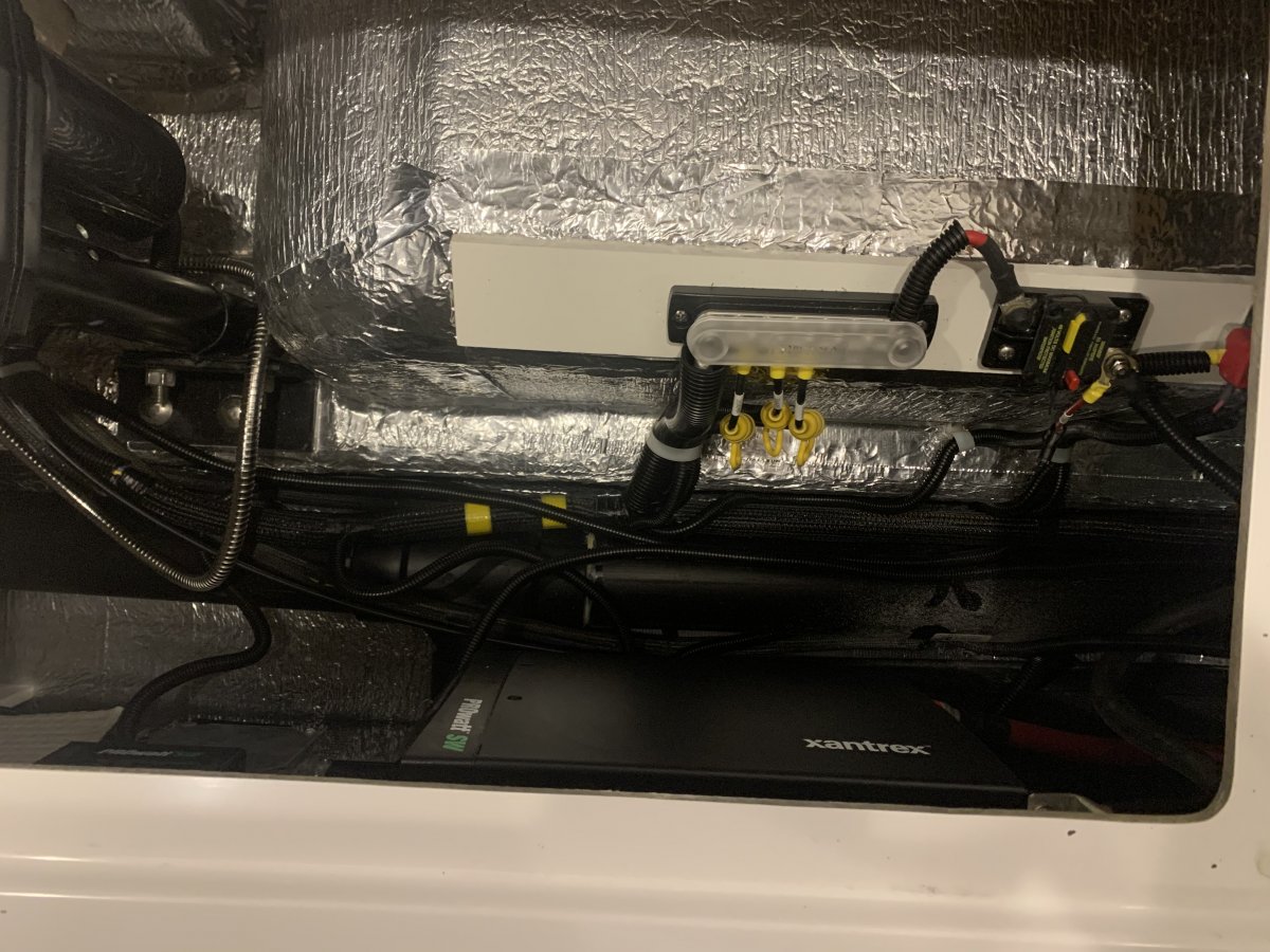
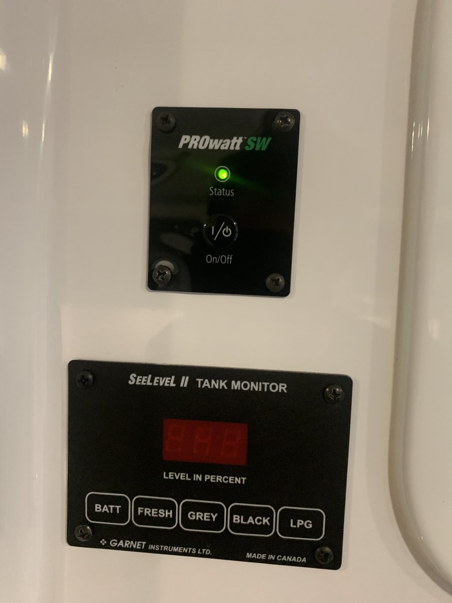
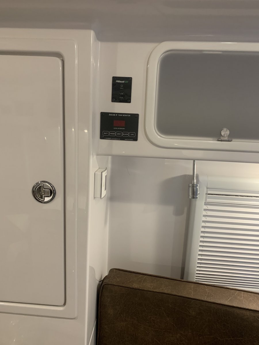
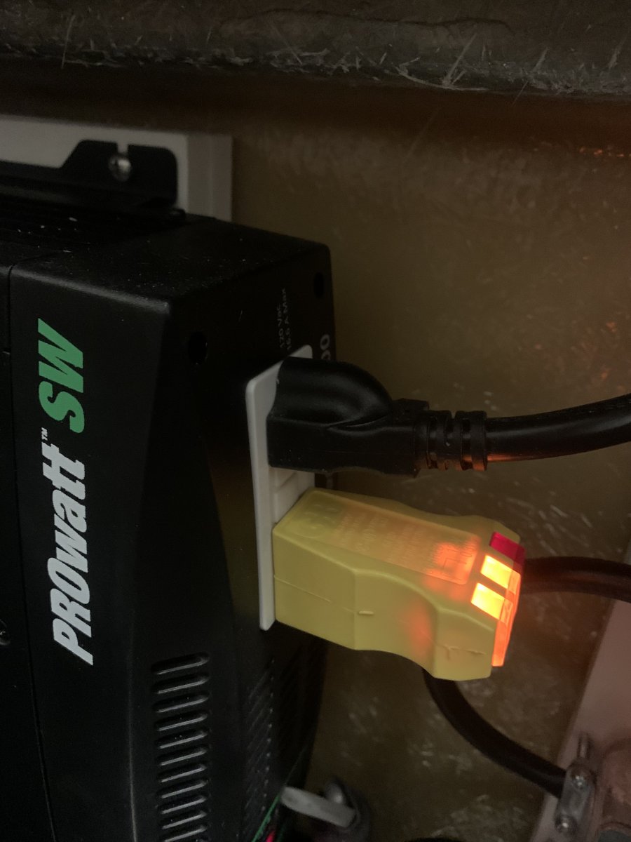
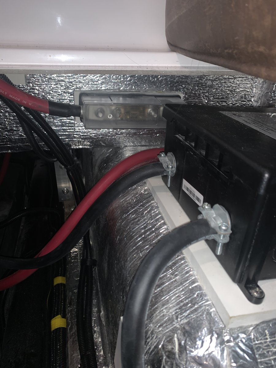
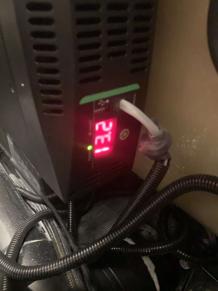
From past posts, it looks like you may have bought 183? If so, it should have the Xantrex inverter. Some of this has already been suggested but I've added some photos. These come from 365 but it should be close to what you have. Your issue may be as simple as put the ON/OFF switch to the ON position. Don't worry, we've all done it. If it's that, then hopefully these trouble shooting tips will help someone else. If it's more than that, here are some additional things to look at. 1.) Check that the inverter is turned on at remote (green light in "Inverter Power Control Close-up_ON" photo). If the green light will not turn on, proceed to step 3. 2.) Check the power indicator at the bottom/back of the inverter. The indicator should be green and the red led should cycle to show voltage in (see photo "Inverter Control and Power Display"). If power comes on, proceed to step 4. 3.) Turn on inverter at inverter by pressing the green power button next to the LED display (noted above). - If power comes on, re-seat the "phone" cable just above the LED display. This is the cable to the remote power switch in step 1. Proceed to step 2. - If inverter did not turn on, it may have failed or is not getting power. Proceed to step 5. 4.) Check the GFCI outlet on the back of the inverter located under the port side bed (twin models) or port aft dinette seat (standard models). Check that the GFCI is not tripped. (See photos "Inverter Power Outlet_GFCI"). Check power at the outlet by plugging something in. (See "Inverter Power Check") If power is good at the inverter, make sure the 120 volt plug is fully seated and re-seat the plug at the inverter as it feeds other outlets in the trailer. 5.) If you can measure voltage, check for 12 vdc at the inverter. If voltage is good, I would suspect the inverter. If no voltage, trace back to batteries. This will include the large ANC fuse under the forward side dinette (see photo "ANC Inverter Fuse). Be care, these cable can draw a lot of power (see photo "ANC Inverter Fuse" top of photo, fuse block connected to large red cables). Check positive voltage both sides of fuse. Let us know how you make out. For the moderators, maybe a section on trouble shooting tips? - Randy
-
Here's another idea. Not a mountain bike though. https://www.tuckbike.com/ I would have a hard time trusting the wheels/tires. I've been over the front of my handle bars before. Fortunately I was younger and more "pliable" when that happened. - Randy