

rideadeuce
-
Posts
152 -
Joined
-
Last visited
-
Days Won
10
Posts posted by rideadeuce
-
-
12 hours ago, Ty J said:
How noisy is your unit when running
So far, no vibrations just some low humming but acceptable (muted by mattress). I did glue down a rubber mat on the basement floor before weighting the aluminum base and then setting HDPE board to wall with epoxy.
-
 1
1
-
-
31 minutes ago, Ty J said:
have ordered the new victron 12v to 12volt charger to charge my Battleborn batteries as the efficiency is 95 percent or more on the unit. I am going to charge those
My next project as well. New 50amp version is nice.
-
4 minutes ago, Wandering Sagebrush said:
Looks interesting and nice. How will you protect it from weather?
Custom cover but it has some weather resistance, for the first time, built in as well.
-
 3
3
-
-
26 minutes ago, John Dorrer said:
We have had a Goal Zero 400 Lithium power pack for 4-5 years.
What you have had is Li-ion NMC. Lithium but very different than LFP technology. GZ first LiFePo4 solar generator was the Pro 4000.
-
2
-
-
https://goalzero.com/collections/escape-ecosystem-off-grid
They sell lots of different integration kits for off-grid use. So It can definitely be the primary power in ones TT but my specific application is trying to use it in conjunction with a Multiplus II. For me, I believe it will have to be used boondocking for powering external equipment only. But all in all, tremendous upgrade for the GZ line of solar generators. LiFePO4 finally.
-
2
-
-
Heavy but nice backup and works seamlessly with all their solar panels. 30 amp plug in back. 3600 watt inverter. 4kWh backup expandable to 20kWh. Lockable mount.
The one drawback to installing the MP2 the way I did was that it has to be on for power to pass through (shore or gen) so I haven't figured out yet if the Yeti can only be supplemental power outdoors, etc or if there is a workaround so it can actually be main power backup.
Best, M


-
 1
1
-
-
These work great for a tandem axle trailer! All 4 tires rock solid, easy to set-up and take-down.
-
3
-
-
On 4/18/2024 at 5:27 PM, katanapilot said:
I was referring to the BMV and Multi Control. Are they not redundant with the GX?
So after finally getting the Victron and Epoch batteries talking and getting use to all the settings via the VRM online I would agree that the BMV and Multi Control are redundant. But redundant in the way you have volume control through software and a physical volume knob. I would still install the Multi Control for the immediate physical control but not sure about the smart shunt or BMV because of the built in communication EPOCH utilizes. Hope this helps.
Best, M
-
1
-
-
Important for Ekrano and EPOCH battery users:
If you use or plan to use the Ekrano display with the EPOCH batteries and Victron COMMS you must go in under Settings and go to Services and change the VE.CAN 1 to CAN BUS 500. Works like a charm now but literally no-one at EPOCH or any installer I talked to knew how to do this. Once done the batteries BMS talk to the Victron Components and take over charging parameters/needs. If you are using the Cerbo GX just plug into Can Bus port.
-
2
-
2
-
-
Quote
Shore/gen-> ATS->EMS-> Multiplus-> Breakers. When I removed the old inverter, I took down that part of the circuit and placed it back in the panel breaker (plugs/microwave) and then ran the shore power through the MP2 AC IN the AC OUT1 to the panel.
-
1
-
-
No, they are not redundant both do specific functions that you cannot do with the GX. So in my opinion necessary to get full functionality with Victron system. The only thing that might get rid of smart shunt and BMV is if you use Epoch batteries because their BMS communicates with Victron via BMS Bus on Cerbo or the VE. Bus on the Ekrano. I can't confirm how well that works yet because I installed the Ekrano and I am waiting on a cable that converts CAN bus to VE. Bus. So Epoch batteries BMS is not talking to Victron yet. Doesn't matter if you're using Cerbo GX it will work but Ekrano not sure yet.
-
2
-
-
3 hours ago, katanapilot said:
Why the multiple control/indicator screens? Will the GX Touch not do everything you need, or was this just to fill previous holes in the walls?
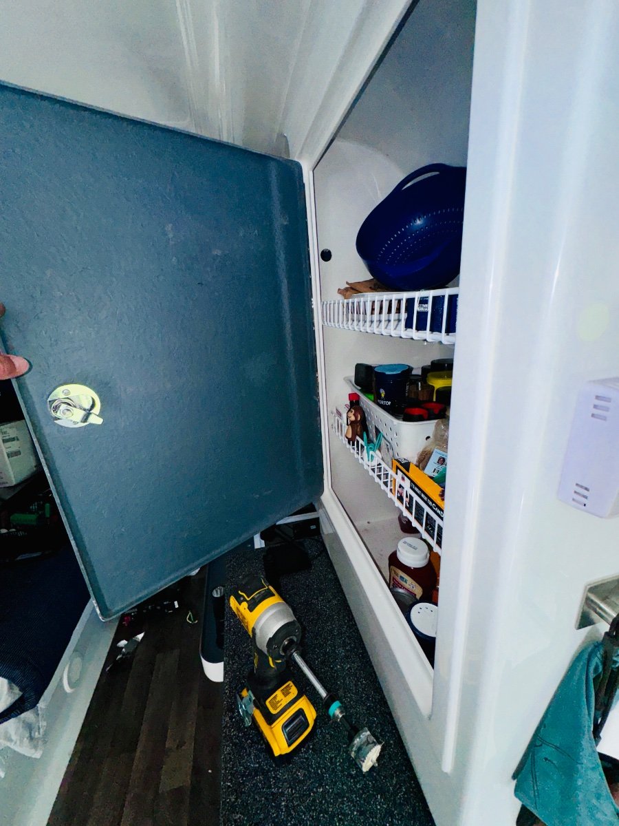
Top right is battery indicator in red supplied by Epoch (quick visual). Under that is the Victron toggle for inverter and power assist control. Old Zamp controller area is for GX display. 2 green buttons inside pantry are remote battery shutoffs.
-
2
-
-
So everything is working. A/C is running off the batteries as we speak. Woohoo! Shore power to ATS to EMS to MP2 AC IN then AC OUT to panel. GFCI circuit hooked back in to panel, all shore power running through MP2. Finally.... WOooohooo... and power assist is so cool.
Still have to mount the Solar charger.
-
2
-
2
-
1
-
-
So problem solved regarding no power to cabin. I had left off the main neutral to the bus bar. I had tucked it out of the way and with all those wires I just kept missing it. It was so nice to see the MP2 fired up and everything working in OEM configuration. @Ronbrink, I think you may be right. I have reached out to OTT and support at the place where bought the MP2. I will get it done eventually. At least the bulk of the install is done and I am ready to power some A/C when I get it figured out. Some other small things like the Can BMS port was removed from the new Ekrano monitor so Epoch battery Victron coms won’t work without a cable to convert CAn-BMS to VE.can. Old Cerbo GX has CAN BMS port. Now just to tidy up everything. Made a big mess.
SIDE NOTE: OTT did reimburse me for my coupler and hitch. Jason was very helpful. Still investigating but looks like a one-off still.
Best,
Mike
-
2
-
1
-
-
4 hours ago, mossemi said:
If you have decided where you were going to mount display, I was able to mount a a 7" Raspberry Pi touch display with the Pi mounted to it in the old Zamp CC hole. I replaced that with a GX Touch 70 display in the same location.
I am going to be replacing my old Victron color display (push button) which took the place of the old Zamp solar charger. So yes, doing the same.
For anyone reading the install, this is what I was trying to do without success so far,
"The best place to insert a multiplus is inbetween the ATS (assuming you have a generator) or shore power input (if you don't) and the breaker panel itself. That way the shore or generator power will charge the batteries, and the inverter itself keeps the power on even without shore or generator. It also enables the power assist mode to function correctly, where you can dial down the current limit to match the available power, and then no longer need a power shedding device to avoid overload.
Any outlets that have GFCI then continue to have GFCI as they should. Those that don't are probably better not to have GFCI, as heavy loads (air conditioner, electric heat) would end up often tripping the GFCI inconveniently and unnecessarily.
The one drawback though is that you *must* then have the multiplus in on or charge only mode to have shore power pass through. If you turn it to OFF, there will be no power at any outlet, regardless of the presence of shore or generator power available.
Also, no backfeeding. You don't want to deal with islanding, and you don't have to since the multiplus will do the right thing if wired correctly. Shore/gen (or ATS) is connected to AC IN1, and AC OUT1 goes to breaker panel. That's it. You *can* use AC OUT2 to switch additional loads based on other criteria (see relay assistant for control of ACOUT2 relay) but that would require an additional breaker as you couldn't then put that switched power through the existing breaker panel.
Note that if you have an existing converter/charger plugged into power from the breaker panel, this will have to be removed/disabled to avoid setting up a loop (120->12->120->...)
This is all assuming you have a single phase breaker panel, or one where the two phases have been merged with a jumper wire (also assuming 30a 120vac service here, not 50a 240/120 split, in which case get a multiplus2-2x). If you do have a 30a split panel (where an existing inverter has already been wired in) you would need to either connect it up the same way as the original inverter (one side of the split is "shore", the other side is "inverter"), or if you wanted to power everything through the multiplus (gain ability to operate aircon from battery) then you want to merge the two sides of the split (jumper between the two 30a breakers) and wire the multiplus in as above (shore/gen->ats->multiplus->breakers).
I do this on a regular basis (upgrading mostly b, some c class RVs).
-
1
-
1
-
-
Day #3
Wired in the MP2, Pos and neg bus bars, smart shunt.
Turned on inverter... Microwave works nothing els. AC plugged in... nothing. Oh well, had fun installing the hardware and attempting electrical.
So everything is mounted except Ekrano display. May give the project a break for a few days and then wire the inverter back to OEM configuration and then hire an RV electrician or talk to OTT to make the changes necessary to use inverter for AC.
Best, M
-
1
-
1
-
 1
1
-
-
4 hours ago, mossemi said:
I was curious about your use of HDPE and PC-11 Epoxy as I haven’t ever tried using the 2 products together. I haven’t used any of PC-Products line of adhesives, so I went their website and looked into their does and don't. I found the information below, so I will be looking forward to your results.
Mossey
Mossimo, that is interesting. Figures I would pick the one epoxy that does not stick to some plastics. The good new is that is rock solid as of now and most of the weight is being held up by the aluminum supports. I did buy the Marine EP-11 which is stronger than the original formula. I don't know if that makes any difference. Thanks for pointing that out that information though.
Best, M
-
HDPE Marine Board from Buyplastic.com. 12x27x1. It is heavy and expensive but turned out to be very well suited for this install. $57.00
PC-11 Epoxy adhesive paste. 1 lb in 2 cans. from Amazon.com
-
1
-
2
-
-
DAY #2
Yes, it is. Costly and ended up not fitting very well for this application without a lot of customization. So it gave me the idea of making my own mount with the heavy duty star board I did not want to use. Turns it out came in very handy!
-
1
-
1
-
-
29 minutes ago, rich.dev said:
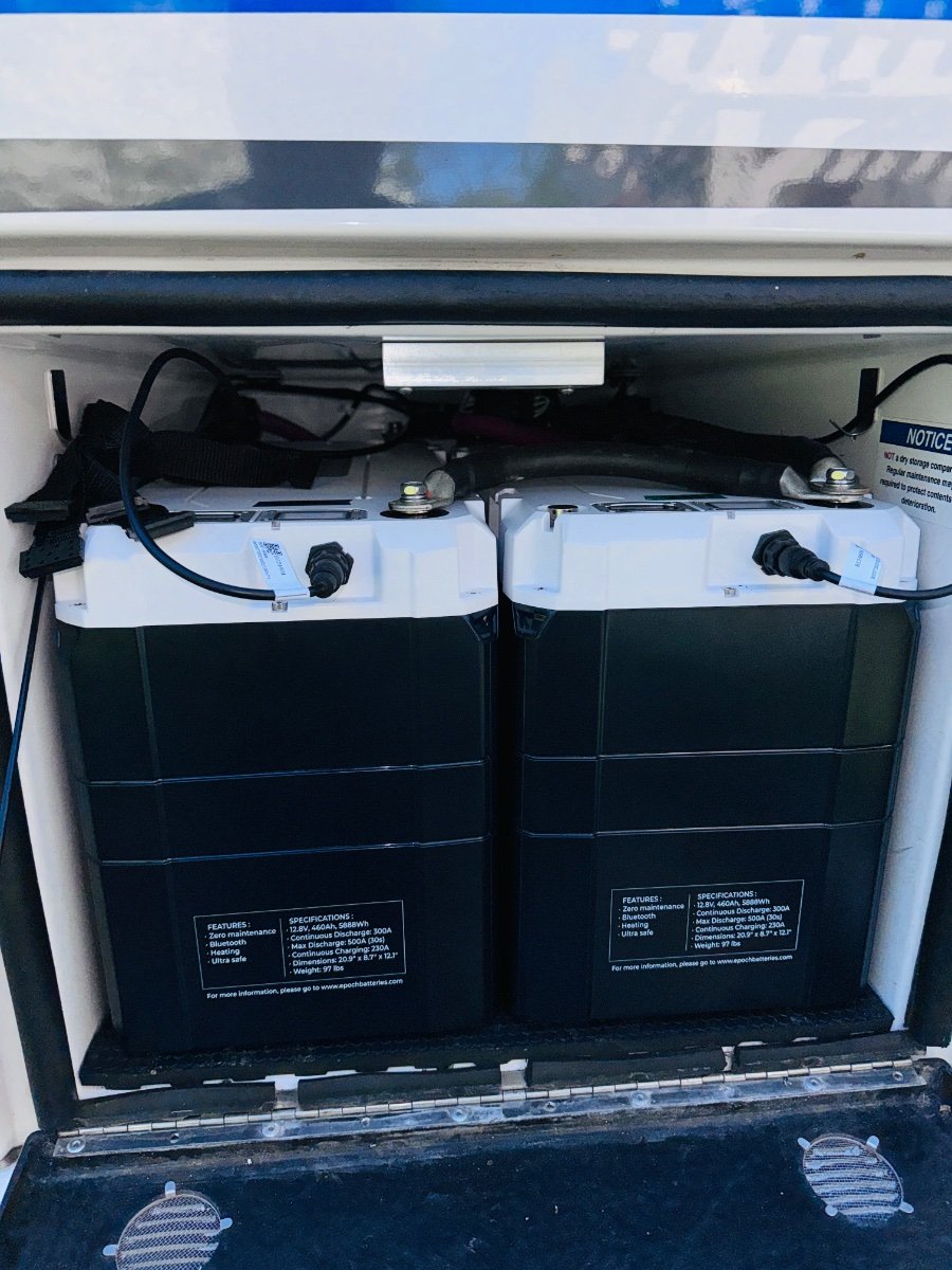
A pity you couldn’t keep the battery slide with the new batteries!
Packed to the gills. I felt like a German mechanic changing a water pump connecting batteries but I am happy with the result. No maintenance and they have remote monitoring and shut offs so they shouldn’t need to come out.
-
8
-
2
-
-
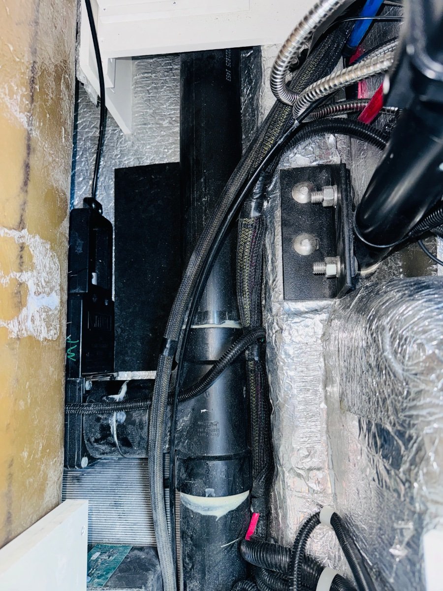
Removed: Old Xantrex inverter, transfer switch including ac legs IN/OUT, charger from PD4000, Trojan batteries, Battery tray
Mods: Wired Outlet and microwave circuit directly to breaker, mounted pos and neg bus bars using Star board (heavy), Pulled all wires from battery compartment except 4/0 pos and neg, ran wires for Epoch battery remote battery on/off switch and external battery level indicator, COM port from battery to MP2, Re-used all electrical wire (Used some new lugs and heat shrink), removed 10/3 main shore AC from EMS to PD4000Installed: POS and Neg bus bar, (2) Epoch 460 ah batteries, battery wire zip tie holders
Waiting on MP2 stand to give lateral support since it will be mounted horizontally. May still bond starboard to fiberglass wall to fixate MP2 but it weighs 49lbs so I want the extra support from stand. We shall see if it fits with some modified aluminum support for feet.
-
3
-
3
-
1
-
-
Anyone know what the name of the material that is used in the basement for mounting electrical components. It is strong and lightweight. Most boating HDPE and marine lumber material is very heavy. Or any ideas for using something else? Trying not to use wood.
M
-
@Galway Girl What are your thoughts about this. Connect the original jxn box AC IN and AC OUT together to complete circuit for outlets and microwave. Removes the transfer switch and inverter from circuit.
Then take main shore power from EMS that goes to PD 4000 and run it to AC IN on MP2
Then run AC LINE 1 OUT from MP to PD4000 main input.
ALL the power from shore/Gen runs through EMS then to MP2 and then back to PD4000 main, thus distributing to all circuits including air conditioner.
-
Thank you. I think we were reading the some of the same information.
"AC-Out-2 supports loads that you only want to run when on shore power or generator. "
34 minutes ago, Galway Girl said:You might try asking service how they connect up their 3000 watt inverter to run both a/c and outlets.
Yes, unfortunately they don't show their electrical schematics on new systems with 3000 W inverters it seems.


7 pin Trailer plug replacement
in Ollie Modifications
Posted
Plug needed changed plus I need to be able to disconnect the black accessory power due to large LFP battery upgrade. DC to DC charger next addition. Black was already loose. Glad I found it and got trailer plug replaced. Plus thanks to one of the forum members I got the idea to add housing storage for it. Thanks!
OP
