dhaig
-
Posts
133 -
Joined
-
Last visited
-
Days Won
1
Everything posted by dhaig
-
@ghopkins1033, Yes, we still regularly use our exterior towel bar assembly. It has held up well. I have not had to replace any components. I had added two support tubes which connected to two tees in the outer bar, at the suggestion of @Bill and Nancy. The support tubes had suction cups at the opposite end to connect to the body of the trailer at approximately a 45 degree angle. I no longer use the two supports, due to another suggestion from @Bill and Nancy. @Bill and Nancy, operate The Bird Store, which offers bird feeders which utilize suction cups for mounting. They recommend their customers apply a thin coating of petroleum jelly or olive oil to suction cups to improve their holding capability on smooth surfaces. The lubricant applied to the primary suction cups eliminated the need for the additional supports. I now apply a very thin coating of petroleum jelly or olive oil to the 4" primary suction cups before mounting the assembled rack to the body of our LEII. The addition of the lubricant to the suction cups substantially increases their holding capability. The two 4" suction cups now easily maintain a load of as many towels as we can fit on the 4 tubes of the rack. The suction cups are easily removed by raising their levers and lifting an edge of the suction cup. A plastic putty knife is also useful for releasing the grip of the suction cups. We have learned to use clips on towels/clothing hung on the PVC tubes of the towel rack to prevent the wind blowing them off. The clips also help to keep the towels from blowing against the body of the LEII, which is not always free of road grime. I usually put a clip on a towel just below the PVC tubes, holding the towel on either side of the tube. We have found clips for chip bags serve well for this purpose. Walmart is a reliable source of inexpensive clips. I usually assemble the towel rack on a picnic table, where I also apply the lubricant to the suction cups. A small amount of lubricant also helps the PVC tubes to slide more easily into the couplings. Disassembly is very quick. Little space is required for stowage when knocked down. Regards, Don
-
@jd1923, the remote control for our MaxxAir fan (2022) has 8 buttons, as does yours, but a different key arrangement than yours. It appears to have the button functions corresponding to yours. There is a button on my control showing an icon of an opening cover. When I press this key, to fan cover opens, but the fan remains OFF. Have you tried pressing the VENT OPN/CLS button? This may do what you want. Regards, Don
-
To Central Texas from Central Arizona the Slow Way
dhaig replied to jd1923's topic in Campgrounds & Parks
RV LIFE Trip Wizard also has filters for city and county parks, 2 of the 12 categories of park types it offers. @jd1923, kudos for assembling the route plan you posted. I learned there are categories which deserve more of my attention when planning routes. Don -
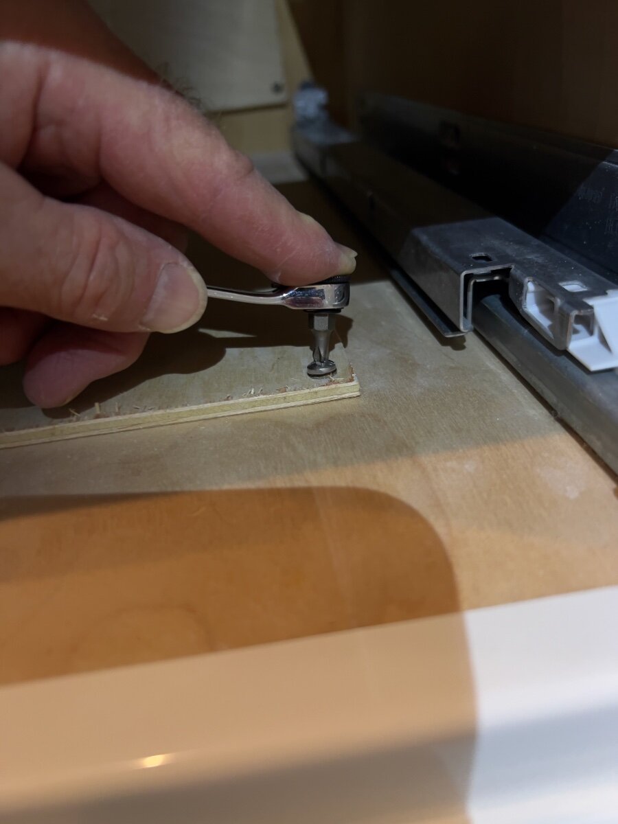
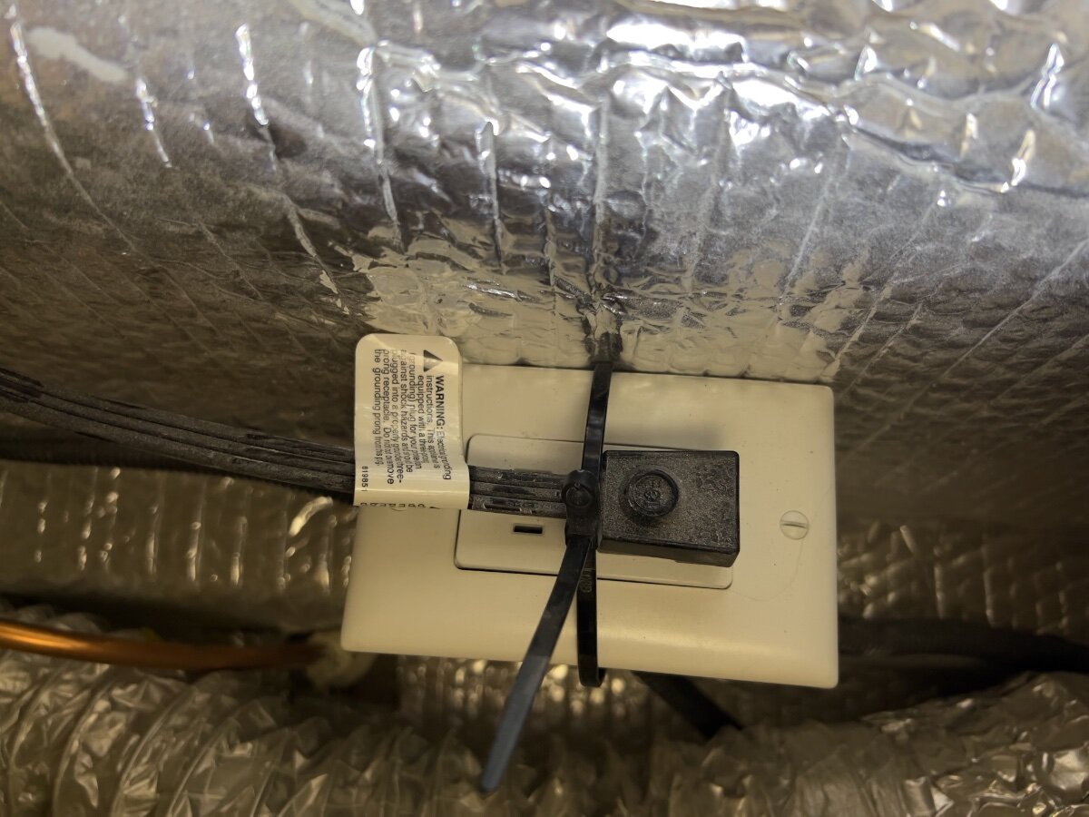
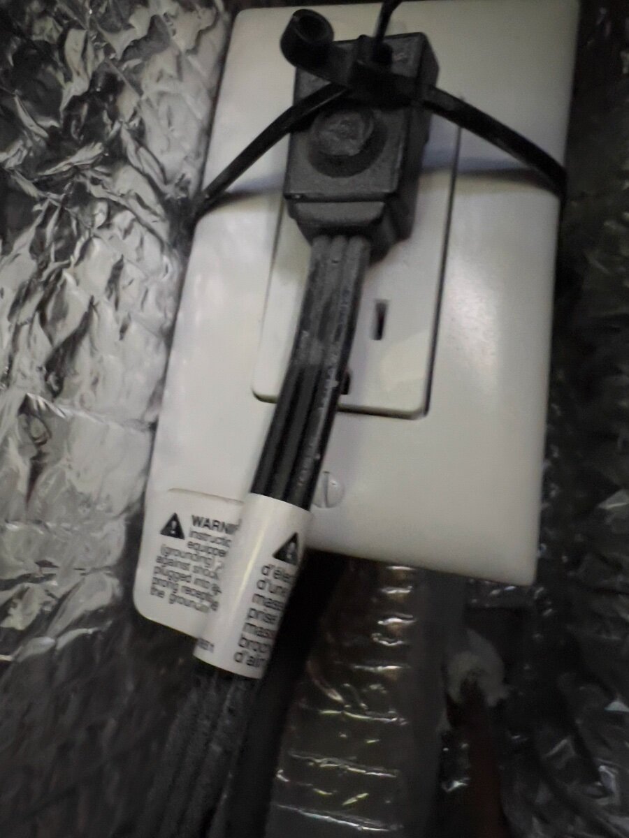
Yesterday, I retrieve OTT LEII Hull 990 from storage to prepare for a photo trip to shoot fall color in The Smoky Mountains National Park. Upon arrival home, I unhitched, connected shore power and turned ON the Norcold 3-way Refrigerator. The refrigerator would not startup on AC shore power and the fault indicator on the door displayed an "A". I consulted the Norcold N41x_ N51x_Service Manual and found troubleshooting steps in P. 21. I checked the AC breaker in the power panel under the rear dinette seat, which was ON. I checked the GFCI protected outlets and they were ON. Next, I removed the exterior access panel to the refrigerator, next to the entry door. I removed the AC supply line from the refrigerator (located in the lower left, near the control board cover) and found NO AC voltage on the supply line. This morning, I phoned OTT Technical Support and described the problem and symptoms and asked if there we any other breakers or fuses between the breaker panel and the refrigerator. Mike Strong informed me there were none. He did, however, tell me the refrigerator AC supply line plugs into an outlet below the left/forward galley drawers. This outlet is accessed by removing the bottom two drawers and removing a thin plywood hatch attached with four wood screws to the bottom panel of the drawer cabinet. I proceeded to remove the drawers and found the plywood panel. Removal of the wood screws requires a short Phillips screw driver. I used a small ratchet set with a ¼" Phillips No. 2 bit to remove the screws. I found the outlet and the AC supply line to the refrigerator. The AC plug was partially dislodged from the AC outlet. I reinserted the plug and tightened the zip tie, which had been installed to prevent the plug from vibrating or otherwise coming out of the outlet. With AC power restored, the refrigerator now operates normally. The first step in the troubleshooting flowchart on P. 21 of the service manual calls for checking the AC power input to the refrigerator. However, it provided no clue to the existence of the concealed AC outlet beneath the galley drawers. My thanks to Mike for informing me where to find the concealed outlet. Our trailer was delivered in mid-February, 2022, and now has traveled over 12,000 miles. I suspect the cause of the AC plug dislodging from the outlet was vibration while underway. I would expect other OTT owners will have similar experiences. See photos below. Access hatch removal AC outlet as found with plug dislodged (note position of zip tie) AC outlet and plug with zip tie relocated and tightened Regards, Don

- 1 reply
-
- 3
-

-
@Blain, Champion Power Equipment offer a number of dual fuel models, including a 3400 watt model, which can produce a maximum of 25.5 starting amps and 23.3 running amps when running on propane. The downside of this larger capacity generator is a weight slightly over 95 pounds. In contract my 2500 watt generator (Model 200961) approximately 40 pounds. Check the specs of these generators to ensure they will fit into the front storage box. You should also check the allowable tongue weight of your tow vehicle to ensure a heavy generator does present too much weight. How did you determine you need a generator capable of producing 30amps? I suggest this is overkill for an LEI. Do you really want to carry gasoline in your tow vehicle? As @dewdev pointed out, our LEII does not have the Truma AC unit. From what I have read on the OTT forum, I expect Oliver will confirm the Truma AC unit has lower power requirements than the Dometic Penguin. I suggest you add details of your tow vehicle and LEl below your signature, which will help other owners to make appropriate recommendations. Don
-
@Blain, I purchased a Champion 2500 Watt Dual Fuel Generator in late 2021, prior to our delivery of our LEII, Hull 990 in February, 2022. See: https://www.amazon.com/Champion-Power-Equipment-2500-Watt-Technology/dp/B0CRLWJSSX/ref=dp_fod_sccl_1/134-9963084-0325038?pd_rd_w=Z6nsM&content-id=amzn1.sym.783fbbc9-65f4-4105-bb20-37dc32815d16&pf_rd_p=783fbbc9-65f4-4105-bb20-37dc32815d16&pf_rd_r=C3KWVM2SBJ484K0Q57BW&pd_rd_wg=GJSmQ&pd_rd_r=3b8f7d10-4b53-41bc-b17e-e7792cfe7baa&pd_rd_i=B0CRLWJSSX&th=1 I have been very pleased with the operation of this generator, which I have operated only on propane. We carry it in a rear mounted cargo carrier on the LEII. I have actually used the generator more often at our residence in Dallas, TX when we have experienced extended power outages. It easily powers a large chest freezer and a 20+ cubic foot refrigerator/freezer. This generator will run 12-14 hours on one 20 pound tank of propane when supporting these appliances. On gasoline, this generator will operate for about 6 hours, depending upon load. This generator can also be paired with another similar Champion generator OR a larger model for additional capacity. I have no found the need purchase a second generator. Not having to haul gasoline onboard is a major advantage. I adapted the fuel hose on the Champion generator to connect to the low pressure connections on our LEII. The Champion 2500 Watt Dual Fuel Generator powers our Dometic Penguin air conditioner on the LEII. We purchased a Micro-Air EasyStart for the A/C unit as an option on our LEII. The generator will NOT power the Dometic Penguin A/C unit without the Micro-Air EasyStart. I did quite a bit of research prior to purchasing this generator. It costs approximately that of a gas only Honda generator and has produces about the same level of noise as the Honda. I also looked at propane conversions kits for the Honda generators and found these were an additional $250 to $300, AND installing them voided the Honda warranty. I would not hesitate to make the same purchase again, if needed. I see no downside to purchasing from Champion. Regards, Don
-
I also use The Collar and an Abus disk lock to secure the Bulldog coupler. Both were sourced from Heartland Lock. I prefer The Collar over other coupler locks, since it can be used to secure the trailer when both hitched and unhitched. In addition, I purchased a pair of chrome steel ball bearings from Amazon. I must give credit to @John E Davies. See:
-
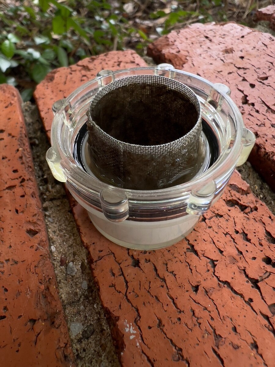
@CRM, if your are experiencing low water pressure when NOT connected to city water, but using the water pump to draw from the fresh tank, then check the filter on the input to the water pump. I recently was investigating an issue where the pump would not draw water from the fresh tank. Upon checking the filter at the input to the pump, I found it clogged with a slimy residue (see attached photo. I removed the fine wire mesh from the filter housing and washed both with Dawn dish detergent. Water flow is much improved with a clean filter.
-
Norcold Refrigerator Not Drawing off Solar?
dhaig replied to Cort's topic in Mechanical & Technical Tips
@Cort, I second the recommendation of @Geronimo John to add ventilation fans to improve the operation of the Norcold 3-way refrigerator. This is not a difficult project. Also, I had little problem routing the fan control to the front cabinet, immediately behind the control panel. Feel free to send me a PM if you have questions. See: -
How To Install a Rear Cargo Carrier on an Oliver Legacy Elite II
dhaig replied to dhaig's topic in Ollie Modifications
@Leftwinger, I missed seeing your request for an article on the installation of the 4 pin wiring harness to provide lights for our rear mounted cargo carrier. I have not gotten around to writing the article. However, if you still would like the details, send me a PM and I will respond. Regards, Don -
@johnwen, you are correct- yellow is ground and red is 12VDC. I believe you were referring to the image below: Please note, I later relocated the fan control to the upper storage cabinet above the refrigerator and microwave oven. The power connections for the fans remained unchanged from what is shown above. Regards, Don
-
@Geronimo John, the airflow around the fans is unobstructed. I suspect what you are seeing is the sloped interior wall above the refrigerator covered in aluminum tape. The fans do pull outside air into the lower vent and out the upper vent, where they are mounted. The flow of air is noticeable and I usually have them running at 50% of max speed, or less. The two fans easily produce sufficient airflow to significantly improve the performance of the refrigerator. Don
-
@johnwen, The fans on our LEII mount to the inner edge of the flange around the vent opening. Not to the slanted panel inside the vent opening. There was no cutting of the fiberglass. In the three photos below you should be able to see the screw heads which clamp onto the edge of the fiberglass. There are also small metal "ears" fastened with hex screws to the fan frame. The combination of the "ears" and the large screw head serve as a clamp. The fans are quite secure using this mounting mechanism. Regards, Don
-
@ThomB87, the fans are installed in the top vent. When they are running the movement of ward air from the upper vent is noticeable. There is very little fan noise. As @Ray Kimsey describes, only a 12VDC and a ground connection are required to run the fans. Attached to the fans is what looks like another wire, but is a temperature sensor. This is run down behind the regfrigerator. A small remote control panel is also attached to the fans with 5 or 6 feet of wire. I ran wires for the remote control up behind the main control panel near the entry door. There is an access hole behind the control panel, with a round cover. This is inside the forward most storage compartment above the refrigerator and microwave oven. I did not like having to remove the lower panel to access the fan controls. Also, the fan control has a bright blue LED which is visible outside the trailer if located behind the lower panel. Access from inside the trailer requires only opening the storage compartment and removing the round cover. This location also contains the annoying blue light on the remote control, which cannot be turned OFF.
-
@Nancy_D, we have a Norcold 3-way refrigerator and use it to freeze the blue freezer bricks. We typically use 6 bricks, in 2 groups of three and rotate the groups as needed to refreeze them. Typically this is a daily rotation. We have added supplemental fans mounted at the rear of our Norcold refrigerator, which make a significant improvement in the cooling capabilities of the Norcold refrigerator, especially when outdoor temperatures are high. If you encounter problems with you refrigerator, I recommend use considering the Beech Lane Refrigerator Fans The freezer bricks always refreeze overnight. I don't know exactly how long they take to refreeze, which will vary somewhat depending on the outside temperature and activity opening the door.
-
Book Storage bins beneath twin bed “Wing”
dhaig replied to Mountainman198's topic in Ollie Modifications
@Mountainman198 great idea? Could you please provide a link to the bins? I had no luck searching Target's website. Thanks, Don -
@Ronbrink, good question, I don't know. I have not opened the Xantrex app at the time the Xantrex Inverter/Charger has been heard to come on. On Sunday, I put our trailer back into storage, probably until January, so I won't be able to check until our next trip. Although I have been told by both Oliver Service and Xantrex "not to worry", I am still curious as to the cause. Also, I have noticed the brief periods when the inverter/charger comes ON mostly during the night, when I am in bed. I have not, so far, been sufficiently motivated to rise and investigate these incidents. We are planning a January trip to the TX gulf coast in January to photograph migratory birds. I will try to remember to check the Xantrex app when I next notice the short interval of operation. Regards, Don
-
@Rivernerd, @Chukarhunter, @Steph and Dud B, @MobileJoy, @aaronorange, @John Dorrer, My issue has been resolved. The Xantrex Inverter/Charger is now charging my Lithionics batteries. As promised, following are the details leading to resolution of the problem. After logging a service ticket (including thorough details) with Oliver on Sunday, 11/12/23, I continued to read the Xantrex owner's manual and search the internet for clues to resolve the "AC bypass" preventing charging of the batteries. This effort was largely unsuccessful. On Monday morning, 11/13/23, I phoned Oracle Service to inquire if they could provide guidance to resolve the problem. In short, they could not. I was told since this was an AC problem, Oliver could not help resolve the problem. They recommended taking the trailer to a service center. In the course of the discussion, I was also provided erroneous information, such as the as the state of the ON/OFF switches on the Lithionic batteries. I was told the batteries are fully charged if the switch button is lighted a steady blue color. This is incorrect. The owner's manual from Lithionics clearly states a steady blue light indicates only that the battery is ON. I knew from using the Lithionics app on my phone exactly what the charge state was- between 10% and 12%. Oliver Service did forward my service request to Xantrex and I received an email from Xantrex which included a case number in their service request tracking system. In the automated email were instructions for submitting additional information. Using the Xantrex FXC Control app on my phone I made three screenshots of the current settings on the Xantrex inverter/charger, plus serial number, purchase date, etc. Below is one of the screenshots. Oliver Service also provided a phone number to Xantrex customer/technical support, (800) 670-0707. I placed a call to Xantrex, only to receive a recorded message stating they were closed for a Canadian holiday. Today, I finally reached Shawn, a Xantrex tech support agent, after about a 25 minute wait in a phone queue. I provided the case number and Shawn spotted the screenshots and quickly reviewed the settings. Shawn told me he was almost certain my issue was caused by the setting of Charger Ignition Control being Auto-ON. While still on the phone with Shawn, I went to the trailer, opened the Xantrex FXC Control app and changed the setting of Charger Ignition Control to OFF. The Xantrex Inverter/Charger immediately came on and began to charge the batteries. Neither Shawn nor I can explain how this setting got changed from the default Oliver setting of OFF. In the two hours since changing this setting the batteries SOC has increased from about 10% to >40%, while connected to a 20 amp circuit. In another hour, the batteries are all near 80% SOC. Lessons learned- I had not checked all of the inverter/charger settings using the Xantrex FXC Control app against the Oliver default settings listed at https://support.olivertraveltrailers.com/portal/en/kb/articles/xantrex-inverter-settings. Had I done this, I may have resolved the problem sooner. In my opinion, Oliver Service should have recommended verifying the current settings against the Oliver default setting for the Xantrex Inverter/Charger and our model year trailer. I had ordered #10 AWG wire and components to add a 30 amp RV outlet to a utility building near our driveway. I am now reconsidering spending about $200 and several hours of labor to do so. The 20 amp circuit already in place seems adequate for our needs when we have the trailer in the driveway. This incident confirmed my prior observation- the lithium batteries can be recharged from a very low SOC to full charge in approximately 4-5 hours using a 20 amp circuit. I have also used this same circuit to run the Dometic air conditioner in the trailer for as long as needed. While I had Shawn on the phone, I asked him why the Xantrex Inverter/Charger would occasionally come ON for brief periods (2-3 minutes) while attached to shore power. I have noticed this occurring at night, such as when the furnace cycled on. Shawn said this was not unusual, if a large DC load is activated, such as a bilge pump, or a furnace blower. I hope this information is useful to other Oliver owners whose trailers are equipped with Xantrex Inverter/Chargers. My thanks to all who offered suggestions to resolve the problem. Regards, Don
-
I also encountered problems with air loss from Shrader valves which would not seat due to obstruction from balance beads. I suspect the problem affects more than 25 trailers. @AlbertNTerri indicated their hull number to be 1125. Our hull number is 990. As had been indicated by nearly everyone posting on this subject, Discount Tire has loyal customers for a reason. I have been doing business with them for over 25 years. I don't recall ever encountering an issue with their service, but do recall many occasions on which they exceeded my expectations. Fortunately, their nearest store is within 3 miles of our home.
-
@Rivernerd, thanks, I was aware I should not use a traditional charger designed for lead acid batteries to charge lithium batteries. I will certainly post on the advice I receive from Oliver Service, and the results. Don
-
@MobileJoy, I had overlooked setting 24, assuming that reducing the value for setting 28 (input breaker size) would result in lower charging current. Now that you have pointed this out, I will reduce the charging current to 15 or 20 amps. The symptoms I have observed lead me to suspect the inverter is trying to charge the depleted batteries at 150 amps, which is obviously not sustainable. Thanks very much pointing this out. Don
-
@Dave and Kimberly, it occurred to me that the current draw from significantly discharged batteries could be quite high, as you described. I have never tried to re-charge from such a discharged state. The most extreme case I recall was recharging from about 50% SOC after having the trailer in storage for a couple of months (placed into storage at ~50%, as recommended). I have tried changing the parameter 28 setting to 15 amps using the Xantrex app, to no avail. I hope to receive a call from Oliver Service tomorrow in response to the service ticket I logged. Thanks for the reply. Don
-
@Rivernerd, thanks for the suggestion. I have previously used the 15 amp extension to provide shore power when at home, using the 20 amp circuit (many times), with no issues until now. I logged a service required to Oliver Service early this AM.
-
@rich.dev, thanks for the suggestion. I was aware of the need to change parameter 28 to match the circuit capacity. I have set it to 15 amps, after having used it successfully set to 20 amps, using the same extension cord and outlet. The surge suppressor display in the attic reports 120V, ~1amp, 60 Hz.
-
My wife and I returned yesterday evening from a 10 day trip, which involved stays at 3 campgrounds. We were tired upon arrival home and I failed to connect shore power to our 2022 LEII with the Lithium Pro solar package. This morning when I went out to unhitch, I found the 3 Lithionics lithium batteries (390 Amp hours total capacity) significantly depleted (12=13% SOC, voltage= 12.5 V). During our 10 day trip the 3 lithium batteries had stayed near full charge, since we were staying at full hookup campsites. On our return trip home, the Norcold refrigerator was running on DC for a total use of approximately 24 hours (10AM departure yesterday to10AM today discovery of low SOC level). The refrigerator load apparently was the primary culprit for drawing down the SOC of the batteries. The refrigerator is now OFF. I connected a 50 foot extension cord, rated for 15 amps, to a 20 amp outlet and to the power port on our LEII. When I checked the remote control display for the Xantrex inverter, I was surprised to see it reported being in "AC bypass mode", which was NOT charging the batteries. This same extension cord and outlet circuit I have used many times when the trailer has been parked in our driveway. I have previously observed the batteries being recharged very rapidly, e.g., from 50% SOC to 100% within 4-6 hours by the inverter. At no time during our trip did I notice anything abnormal in the battery charging. The Xantrex FXC Control app on my iPhone issues a notification "utility power not available or qualified due to poor ac power..." when shore power is first connected to the trailer. The display located in the attic reports normal shore power conditions: 120 VAC, 60 Hz, 1 amp, No error messages (E0). I have previously noticed on numerous occassions when the Xantrax inverter would come ON for short periods (2-3 minutes) while connected to shore power. I have previously asked Oliver Service why the inverter would come on when connected to shore power, when the batteries are at or near full SOC. The most recent answer received was a conjecture that our shore power was unstable. This seems unlikely, since I have observed the short intervals of inverter operation when connected to shore power in many different campgrounds and at our home, where I know we have stable power. I proceeded to read the Xantrex owner's manual to determine how to get the inverter out of AC bypass mode and charging the batteries. I am unable to determine how get the inverter to recharge the lithium batteries. The solar panels appear to be recharging the batteries slightly, due to having a largely cloudy day. Tonight I checked the SOC of the lithium batteries and they have declined 1-2%. I am going to turn the batteries OFF to prevent being fully discharged. Has anyone encountered similar charging issues? Regards, Don