Search the Community
Showing results for tags 'elite 2'.
-
I hope this issue has not previously been addressed on the forum. I could not find anything on this topic with a search. So, here goes. I have always assumed that the fresh water tank in our 2022 Elite II could be filled until water flows out of the overflow tube underneath the fridge, regardless of the fresh water sensor reading. This approach is recommended on p. 61 of our 2022 Oliver Owners Manual: "fill until water starts to run from the freshwater overflow..." I have regularly done just that with no issues--until a few days ago. When filling the fresh water tank, the aisle floor bulged upward, the entire trailer shifted to the curb side binding the door, and then, with a loud CRACK, the backsplash on the sink side of the galley countertop separated by about 1/2" from the fiber granite countertop, because the corner of the countertop near the sink was sloping toward the curbside! After we recovered from the shock, my wife and I immediately ran fresh water (via the pump) into the gray water tank through the galley sink until the trailer shifted back into equilibrium. Fortunately, this enabled the aisle floor to level out again, the door to unbind, and the countertop to slowly rise up again to meet the backsplash, so the two once again line up. When we get home, I plan to re-caulk the joints that separated, and carefully inspect for any additional damage. So far, all appears to be "back to normal" while we continue our extended trip. Lesson learned: despite what is recommended in your Owners Manual, monitor the fresh water tank level when filling, and once the sensor reads close to 100%, SHUT OFF THE WATER! DON'T WAIT FOR WATER TO FLOW FROM THE OVERFLOW TUBE!
-
I searched a lot of content and couldn't find anything like this. Do I have a plugged water line? Kitchen faucet and outside shower work great on fresh water and on city water. But the bathroom sink and toilet have barely a dribble. Before we went out to camp the water system was ok. After traveling just 20 miles or so the bathroom water doesn't work. I found plastic shavings a couple of years ago in the toilet inlet filter. I haven't checked it but that wouldn't plug the sink too. The plastic came from when they post drilled the tank a few year ago I think. I really don't want to make a trip to Hohenwald and back as it's about 760 miles round trip and diesel is hehehe. I know not much about how to clean water lines inside the double hull. How do I attack this problem? Hints? I won't be camping anymore this year anyway. Rhett & Dory Hull #186 2017
-
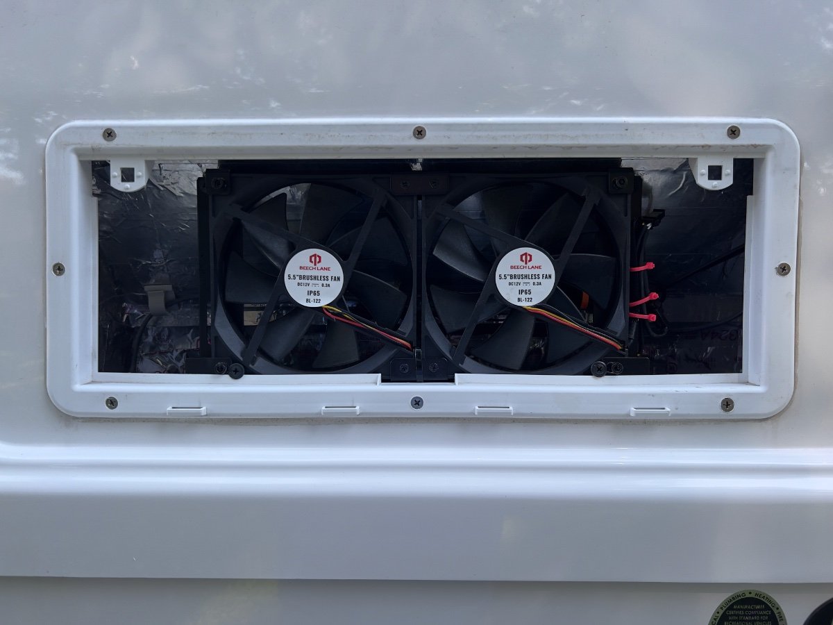
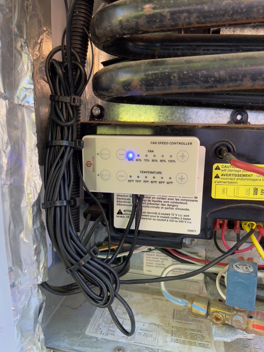
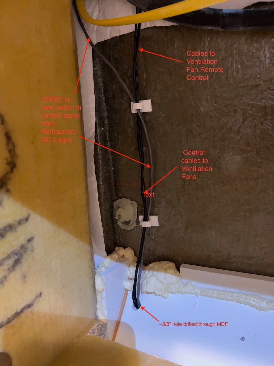
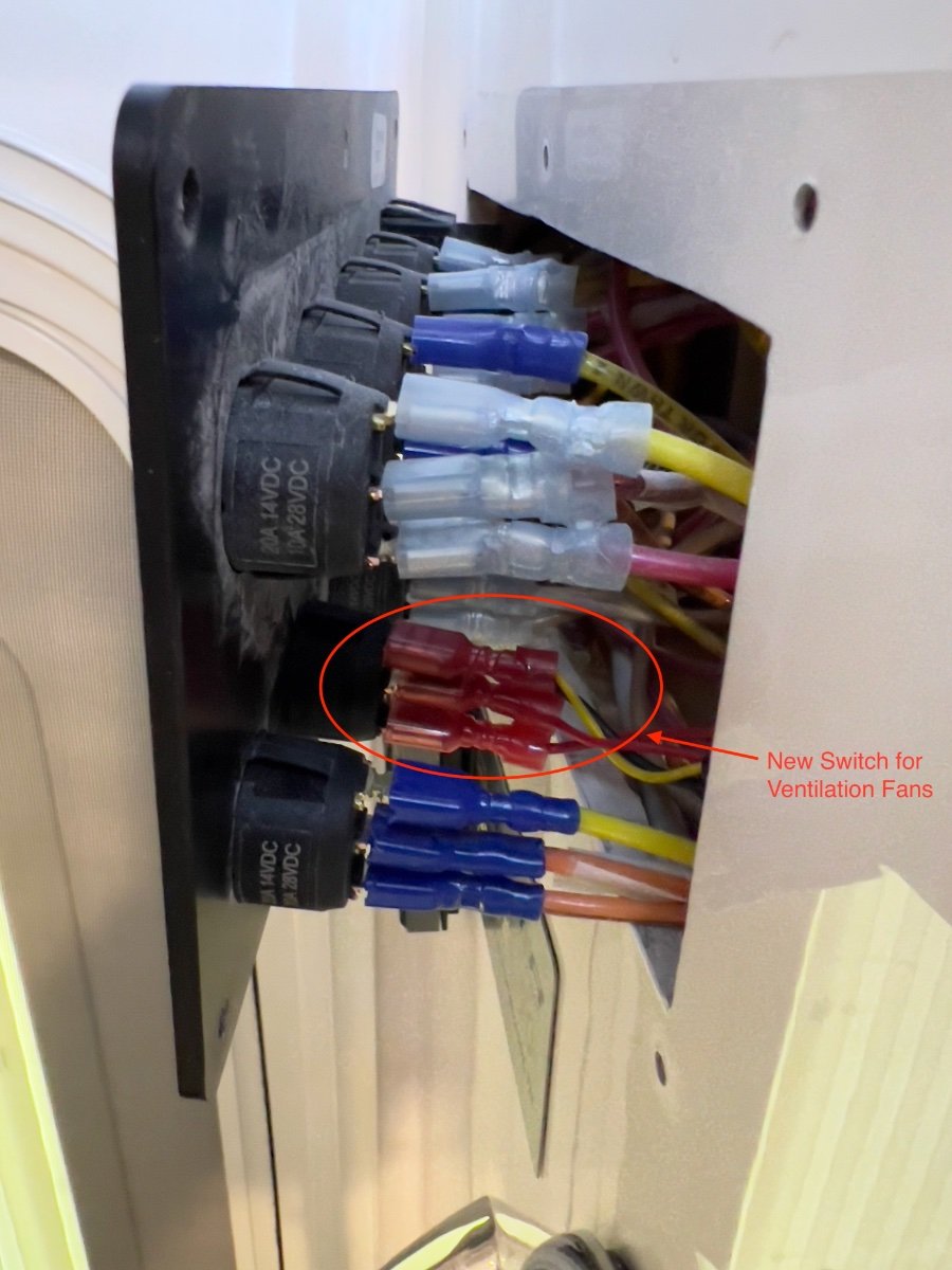
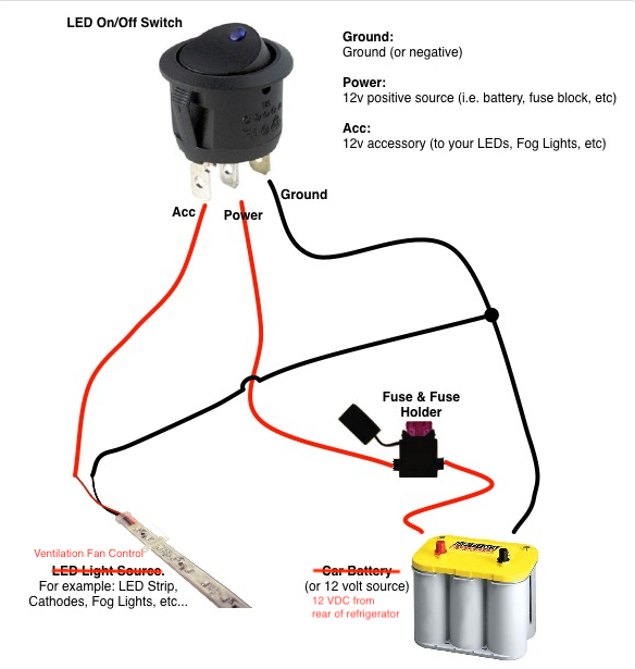
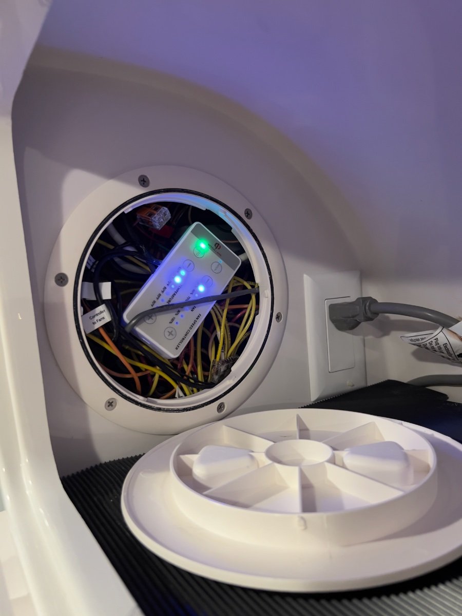
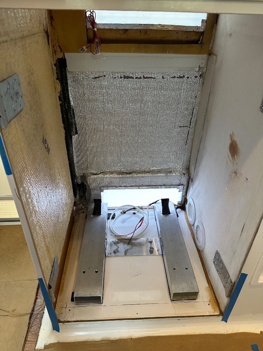
 From late May to mid-June my wife and I took a loop trip from our home in Dallas, TX to: Greenville, SC; Asheville, NC; Asheboro & Seagrove, NC and back to Dallas. The trip covered approximately 1900 miles, with significant temperature variation. During the trip we experienced erratic performance by the Norcold Model 412 refrigerator, standard equipment in our 2022 Oliver Legacy Elite II trailer. The refrigerator would not maintain food safe temperatures in either compartment, except when operating on AC current. This problem occurred mostly on the second half of the trip, as daytime temperatures exceeded 90 degrees (F). Especially when in transit, operating on propane or DC current, the refrigerator temperature would climb to approximately 60 degrees and the freezer into the mid 20s. We contacted Oliver Service and made an appointment to have the refrigerator problem assessed in Hohenwald. We later decided not to divert from our trip plans and to deal with the problem when we returned home. Upon our return home to Dallas, TX, on June 20, I began a series of tests with the trailer parked in our driveway. To monitor the temperatures in the refrigerator and freezer, I used an AcuRite Digital Wireless Fridge and Freezer Thermometer, which we had purchased to monitor the Norcold refrigerator and had been using since September, 2022. I also used an Etekcity Infrared Thermometer 1080 to compare readings with the Acurite thermometer. The AcuRite and Etekcity thermometer readings agreed closely. With the refrigerator empty, I recorded the time required to go from ambient temperature to food safe temperatures using AC, DC or propane. Using AC, the refrigerator/freezer would reach food safe temperatures in 6-7 hours (low 40s F for the refrigerator; 0 degrees F for the freezer) with ambient temperatures ranging from 87 to 99 degrees F. Once achieved, when on AC, the temperatures on both compartments would hold in a food safe range. Conducting the same test on propane, the refrigerator and freezer would reach only 62 degrees and 19 degrees F, respectively after more than 12 hours of operation. This test also was done while ambient temperatures ranged from 87 to 99 degrees F. Similar results were observed while operating the refrigerator on DC. I again contacted Oliver Service and was recommended to take the trailer to an authorized Norcold service provider. Blue Moon Mobile RV (Blue Moon) was determined to be the closest available Norcold service provider. I arranged an appointment to bring the trailer to Blue Moon for troubleshooting of the refrigerator. Technicians at Blue Moon confirmed my observations of the behavior of the refrigerator. They also confirmed the cooling function was working properly, since proper temperatures were achieved when operating on AC. They also confirmed the single, small fan located at the rear of the refrigerator was operational, but providing insufficient air flow for the refrigerator to operate properly when ambient temperatures were high. Blue Moon conferred with Norcold technical support on their findings. Blue Moon and Norcold recommended additional fans be installed to dissipate warm air behind the refrigerator. Having anticipated installing additional fans, I had done online research and chose a dual fan assembly from Beech Lane 12V RV Fridge Ventilation Cooling Fan 5.5" (140mm). These fans come with a remote control with which fan speeds and threshold temperature may be set manually or automatically. These fans were installed by Blue Moon in the upper vent opening of our LEII. The 12VDC power supply to the refrigerator was also used to power the fans. The remote control was mounted to the cover over the refrigerator circuit board using double sided tape. The excess length cables provided with the fans were bundled with zip ties and secured nearby, as shown below. Blue Moon tested the operation of the refrigerator following the installation of the Beech Lane fans and reported food safe temperatures were being achieved and held, with high ambient temperatures. On July 19 I picked up our trailer from Blue Moon and returned home to repeat my prior tests to compare results running the refrigerator on propane and on DC. The trailer was parked in the same location in our driveway as previously. After installation of the ventilation fans, using propane, the refrigerator and freezer compartments achieved safe food temperatures in approximately 8 hours, with the refrigerator control set to 7, despite ambient temperatures ranging from 93 to 105 degrees Fahrenheit. Once safe food temperatures were achieved the refrigerator control setting was reduced from 7 to 6 and allowed to run overnight. The following morning both the refrigerator and freezer had slightly warmer temperatures, but still satisfactory for safe food storage. We have not yet had an opportunity to utilize the Norcold refrigerator on a trip to observe how effectively safe food temperatures are maintained when full of food and under changing environmental conditions using the three power sources. Based on the test results using the ventilation fans, I expect the performance of the refrigerator to be significantly improved. We should now be able to use DC to power the Norcold refrigerator when in transit, and avoid the use of propane. Performance running on DC appears to be similar to running on propane. While I was pleased with the significant improvement in the operating temperatures achieved by the Norcold refrigerator, there were three aspects of the installation I chose to change, all related to access to the remote control: The remote control for the Beech Lane fans has very bright blue LEDs which are ON whenever 12VDC power is ON. At night, we noticed a bright blue glow emanating from the lower refrigerator external vent cover. Accessing the remote control to change settings required removing the refrigerator external vent cover. When we store the trailer we typically turn OFF all DC power by turning OFF our lithium batteries. Upon the next use of the trailer, when DC power is restored, the refrigerator ventilation fans must also be turned ON manually. There was no switch to turn OFF DC power to the remote control. To address these issues, I relocated the Beech Lans fan remote control to the interior of the trailer and installed a switch on the control panel located at the entry to the trailer. I chose to have the remote control inside the access hatch in the storage cabinet located over the microwave oven, directly above the Norcold refrigerator. To re-route the cables to the ventilation fans, I had to remove the microwave oven. To install a new switch in the control paneI I had to loosen the panel from the wall. I had to add approximately 10 feet of 20 AWG twisted pair cable (gray) to reach from the new switch on the control panel to the 12VDC power supply at the bottom rear of the refrigerator. The photo below shows the routing of the remote control wires (black) and 12VDC power supply behind the microwave cabinet. I had to drill a ~3/8" hole in the angled MDF panel behind the microwave cabinet, directly above the refrigerator. I caulked around the cables after routing them through the hole and behind the refrigerator. Fishing the wires into the area behind the control panel was not difficult. The yellow Romex appearing at the top of the photo below supplies the AC outlet for the microwave oven. I contacted Oliver Service and ordered a single pole switch (with blue light) to match the others in the trailer control panel. The cost was slightly over $7, including shipping by first class mail. The new switch was installed in an unused location on the control panel which previously had a blank cover. I added crimp on spade type connectors to the twisted pair cable to connect to the terminals on the new switch. Although the new switch is single pole, there are three terminals on the rear with the wiring connections listed below: Ground (dissimilar color) DC Power IN (center) Switched DC Power Out I found the wiring diagram below which shows an analogous circuit. The switch and the ventilation fan remote control both require a ground connection. The Switched DC power terminal is connected to the DC+ power connection for the ventilation fan remote control. The new switch needs a ground connection in order for the blue light to operate indicating the switch is ON. In the diagram a car battery is shown as the 12VDC source. On the trailer, the 12VDC source is located at the bottom rear of the refrigerator. This DC circuit is already fused at the DC power panel located below the rear dinette seat. I chose to locate the Beech Lane fan remote control behind the access panel in the storage cabinet above the microwave oven. I made this choice to avoid having the bright blue LED lights on the remote control illuminating the interior of the trailer. The access panel is easily removed when there is a need to access the remote control, to turn ON the ventilation fans, or to change the fan speed or threshold temperature. The Beech Lane ventilation fans are very quiet. With the auxiliary fans running, the volume of air exiting the top exterior vent is noticeably greater than with the small, single OEM fan mounted to the rear of the refrigerator. We have not yet tried sleeping in the trailer with these fans running. There is no chance of hearing the fans inside the trailer with the Dometic A/C running. They are not noticeable when they are running unless you are standing close to the upper exterior vent. I recommend these fans to anyone having similar difficulty maintaining food safe temperatures in the refrigerator when ambient temperatures are high. Regards, Don
-
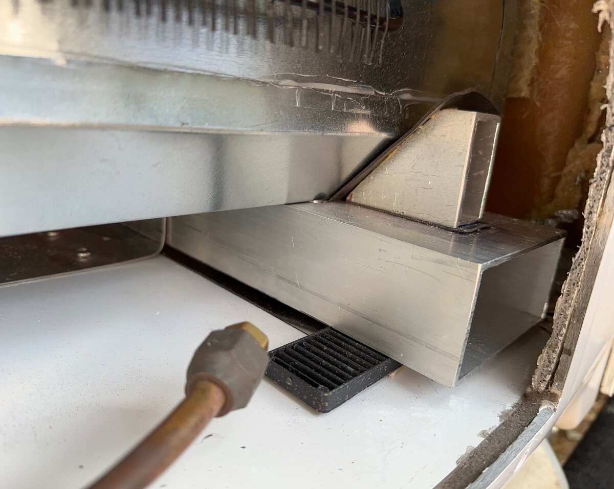
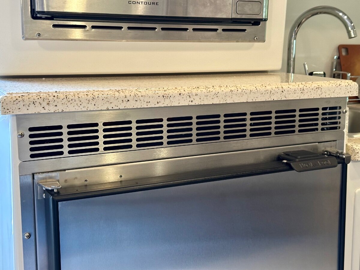
I completed our new Nova Kool R5810 AC/DC refrigerator installation before our trip to the 2025 OTTO's Rally and the 3 week shakedown was everything we hoped for! I want to thank all of the early adopters, Try2Relax, MountainOliver, Geronimo John, Ty J and rideadeuce, who preceded my installation and shared there experiences. I have attached a few pictures that are similar to those that have already been posted. I would also like to shout out to David & Kristine Hess, Cooper Jenkins and the rest of the folks at Sea Biscuit Metal Designs for their help and creation of the upper and lower vents for my refrigerator installation. If you need something custom made from metal, they are my goto team! Mossey
-
I have a few question for those that have experience with the Calmark cover. We are considering purchasing one but I wonder how difficult is it to put on? We have the solar panels, does that make it trickier to pull the cover over them? With our previous fiberglass camper (AS Nest) we were advised by AS not to cover it as the covers can scratch the gel coat. Has anyone had any issues with the finish on the Oliver marring from having the cover on? Any other pros and cons/advice about it would be appreciated. Thank you
-
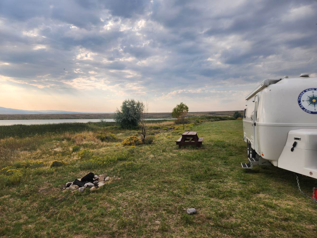
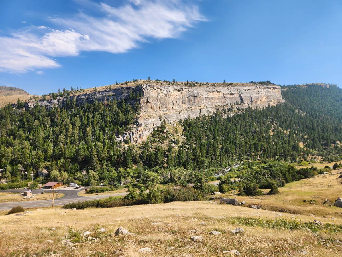
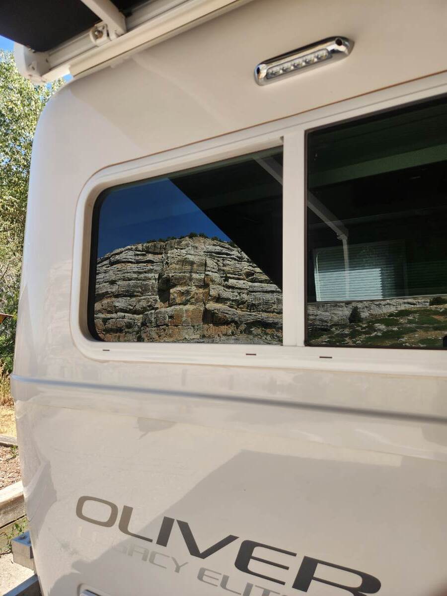
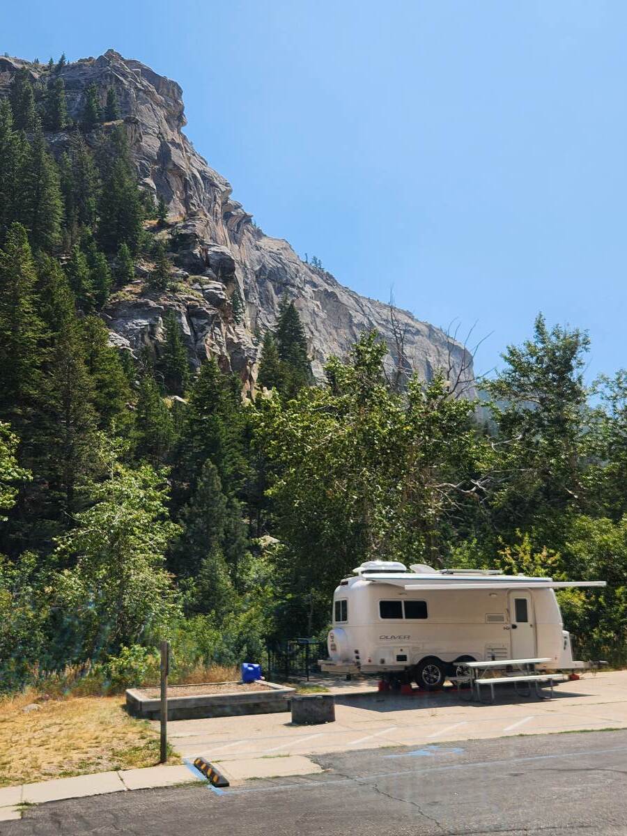
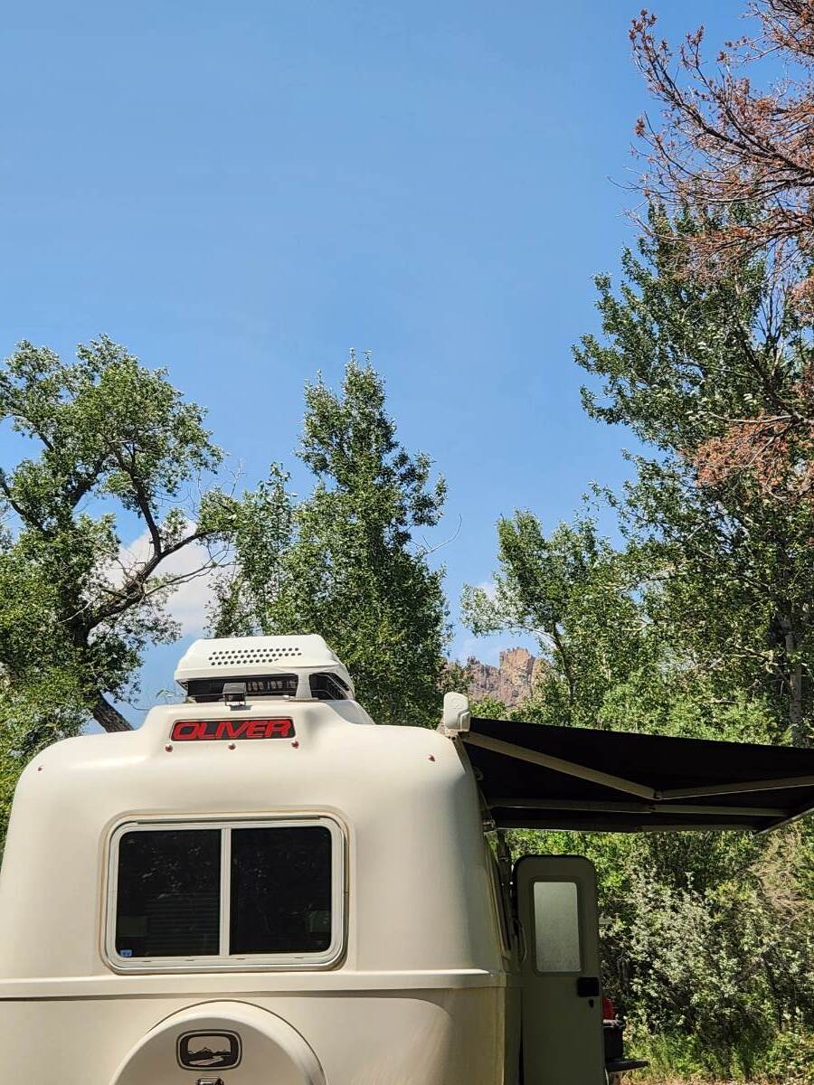
I spent the last week traveling my home state of wyoming looking at properties to potentially buy. I spent the evenings comfortably in my Ollie and got to spend time in some of my favorite places here. I thought I would share photos.
-
- 4
-

-

-
Haloview BT7 Touch Rear Camera installation on 2022 LEII
dhaig posted a topic in Ollie Modifications
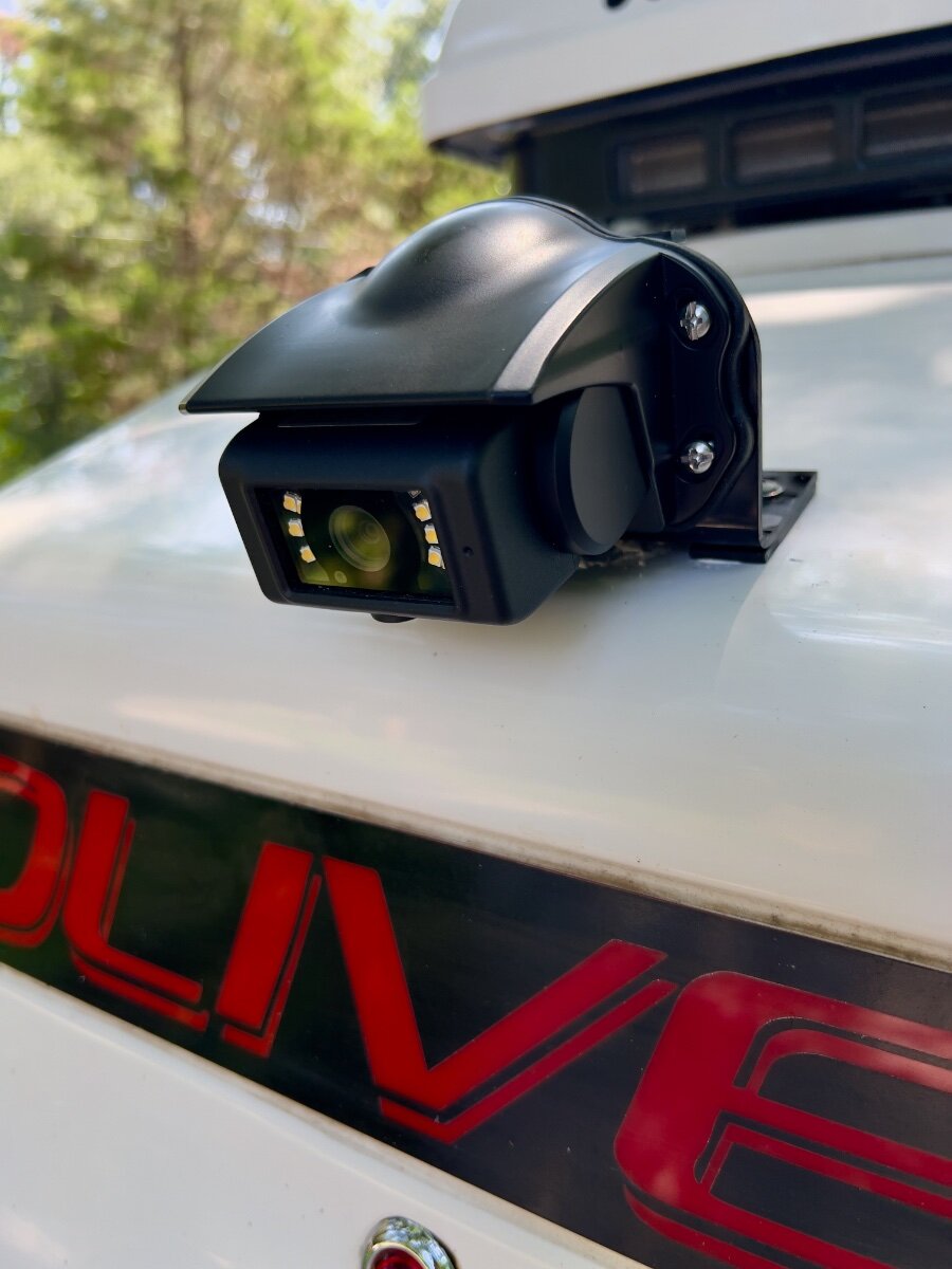
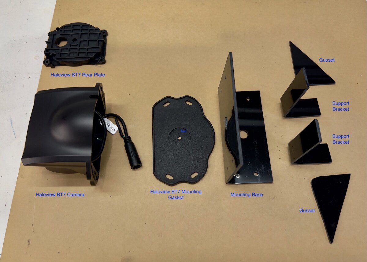
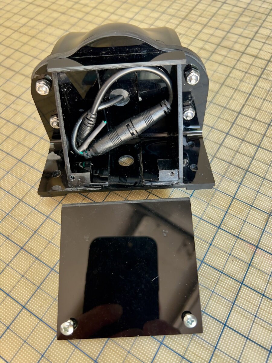
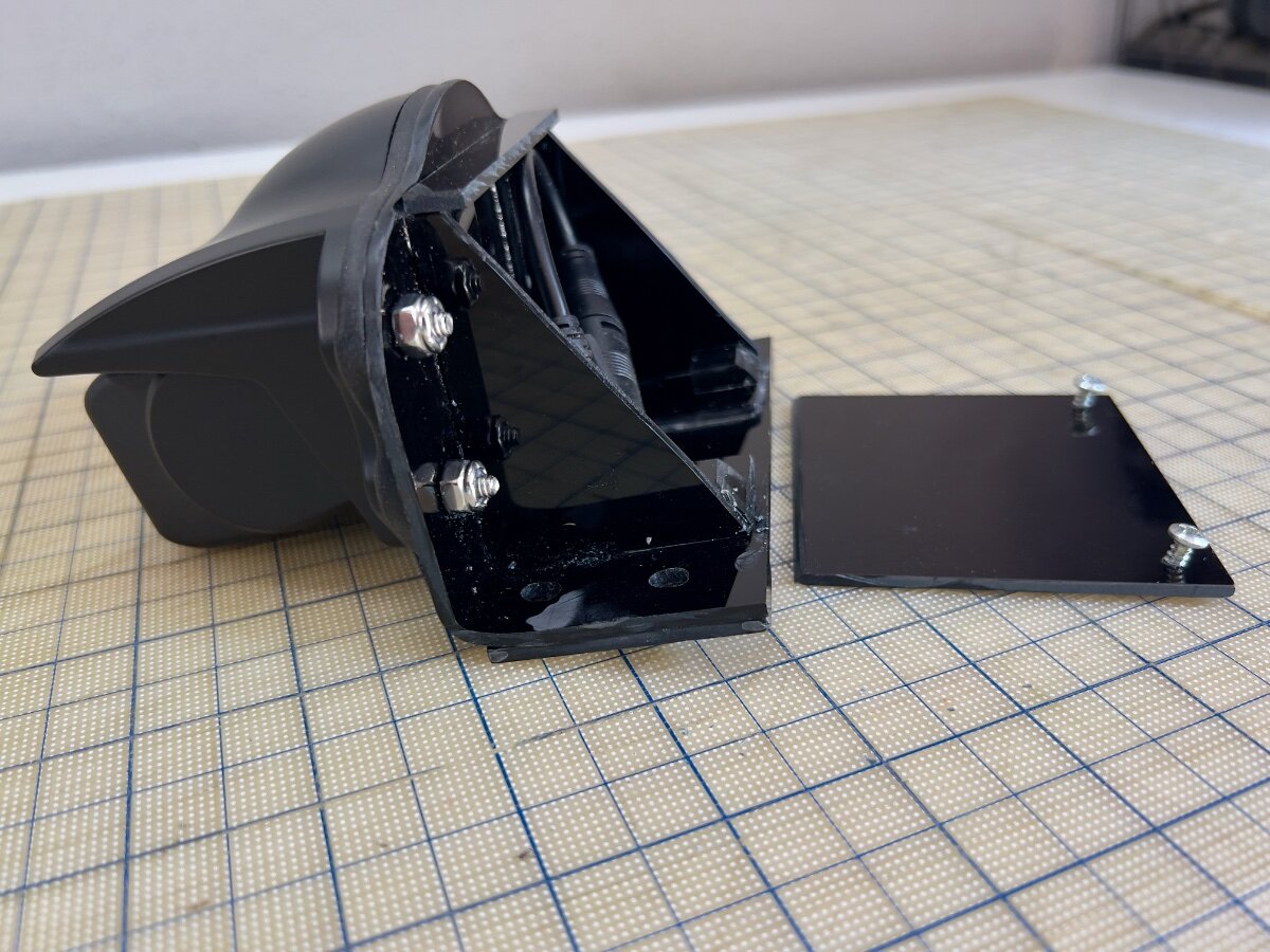
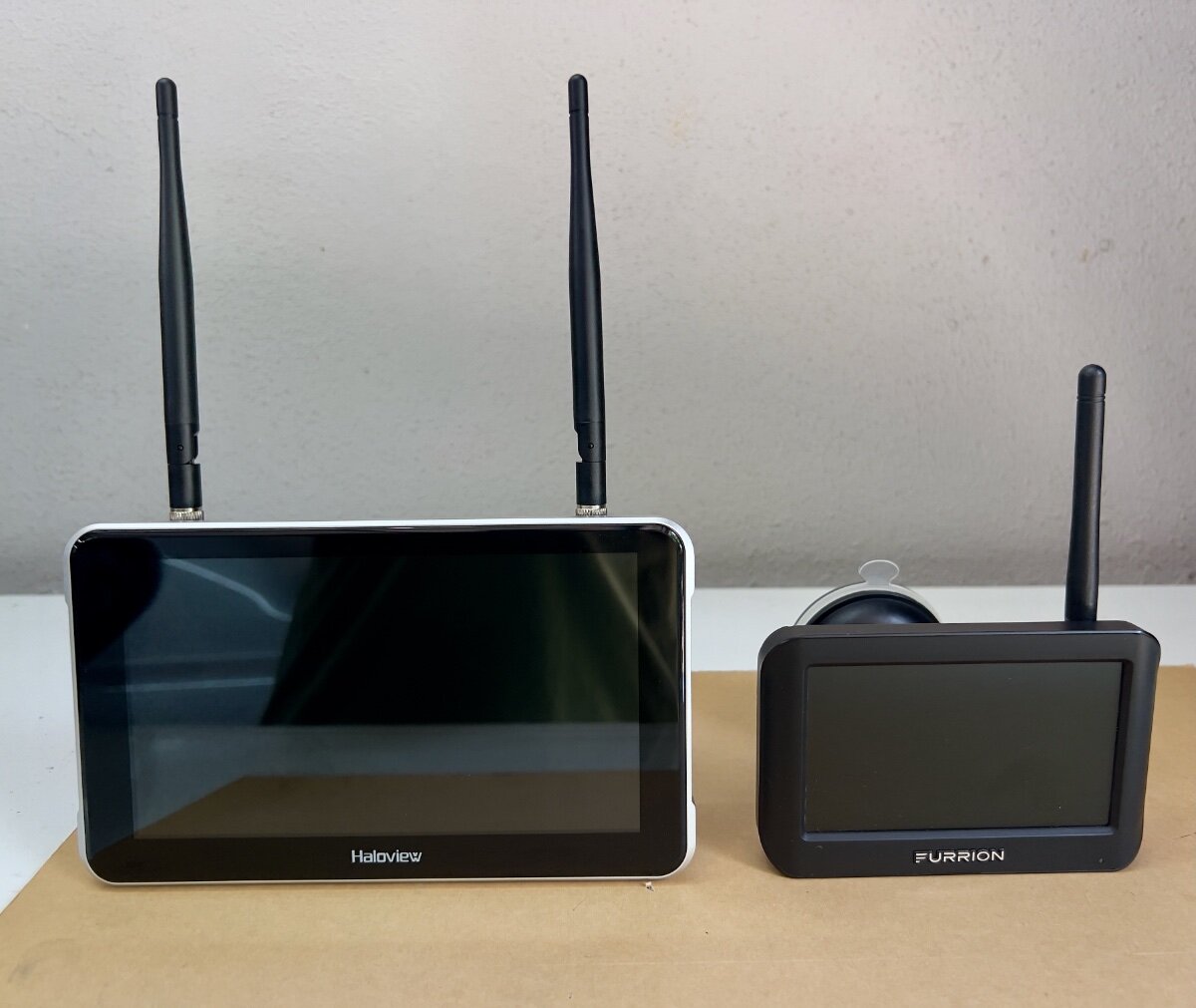
I recently purchased a Haloview BT7 Touch Rear Camera to replace the Furrion Vision S Camera System (Model F0S43TADS) we purchased as an accessory option on our 2022 LEII. Following delivery of our trailer in February, 2022, it was quickly evident the Furrion camera was largely useless. I continued to use the Furrion camera, with increasing frustration. The very limited view to the rear was a safety issue. I began to research RV rear cameras and after reading many reviews selected the Haloview BT7 Touch. I was impressed by the specs and favorable reviews, but failed to note the camera is designed to mount to a vertical rear wall, not the sloping rear roof of an LEII. I could have returned the Haloview camera, but I did not see a good second choice. Thus, I decided to fabricate a mount to be installed in the same position as the Furrion camera. The result is the custom mount below: Fabrication Process I had some black acrylic sheet, .010" thick, from a prior project (See: Window Vent Mod- Louvered Ventilators), which seemed suitable material for a camera mount. I had some thicker acrylic sheet, but decided to first use the thinner sheet to create a mockup by bending the acrylic sheet. Initially, I had concerns the thinner sheet would not be sufficiently rigid to hold the camera steady, but I was not sure I could bend the thicker sheet. The Furrion camera and its mounting gasket were removed from the roof of our LEII and used to begin the layout of the base for the new mount. I wanted to use the four existing holes in the roof which held the Furrion camera in place. I had a scrap piece of acrylic about 7" wide and 20" long. I used 2" blue painter's tape applied to the acrylic and, with a fine point mechanical pencil, began marking out the mounting hole pattern from the Furrion gasket. Next, I flipped the scrap sheet of acrylic over, applied blue tape and began positioning the Haloview camera on the tape. My initial concept was to have the main part of the mount be a single piece of acrylic bent to an angle of approximately 80 degrees. When mounted to the sloped roof of the trailer, the face of the mount would be approximately vertical for mounting the Haloview camera. The layout of the mounting base resulted in the base being approximately 2.0" wide, and the nearly vertical mounting face approximately 3.5" tall. I also allowed about 0.75" for the bend radius. So, before bending the rectangular sheet of acrylic was approximately 6.25" x 7.0". I cut this piece from the end of the 20" long scrap. Before bending, I drilled all needed holes in the mount base, as marked during the layout process. NOTE: See YouTube for many useful videos on bending acrylic sheets. To bend the mounting base, I sandwiched the rectangular piece of acrylic between two pieces of scrap wood approximately 12" x 3", with the acrylic area to be bent aligned on the long side of the wood scraps. I extended the acrylic from the wood scrap approximately 2.5" to 3.0" in preparation for bending. I clamped the sandwiched pieces to my workbench to ensure it would not move during the bending process. Using a heat gun, I began to heat the area to be bent, moving back and forth. Wearing gloves, I held two other pieces of wood, each approximately 2" x 5". As the acrylic became heated, I applied gentle pressure to the extended portion of the acrylic, using the pieces of wood in my hand. I continued to move the heat gun along the bend area until I could begin to bend the acrylic. As the acrylic began to bend, I used care to keep the bend straight and at 90 degrees to the sides. I used a steel carpenter's square to test the acrylic as I bent it. As I approached the desired finished bend angle, I released the acrylic to check the angle. Satisfied with the bend angle I trimmed the top of the mounting base to the contour of the Haloview mounting gasket with a scroll saw. Having the mounting base bent as desired, I began to plan how I would make it sufficiently rigid to hold the camera steady. The photo below shows the other parts which would comprise the rear support area. Also at the rear I wanted to enclose the wiring connecting the camera to the 12VDC power from the trailer. Haloview BT7 Camera and mount parts Once the mounting base was bent as desired, I cut two pieces approximately 1" wide from either end of the mounting base using a table saw. These two pieces became the support brackets. Being bent at the same angle as the mounting base, they fit well to backup the mounting face. The triangular gussets also add rigidity, being bonded to the mounting base and the support brackets. The photo below shows the mounting base (face down) with the support brackets and gussets attached at the rear. Acrylic cement was used to weld all parts together. Mounting base face down with support brackets and gussets in place Side view of mounting base with support brackets and gussets in place To protect the power supply wiring from UV exposure and squirrels, I added a cover and a top piece across the gussets. The rear compartment does not need to be watertight, since the wiring connectors are watertight. Haloview includes a short adapter which connects to the existing Furrion connector protruding from the roof. The photos below show the camera on the mounting base and cover from the rear and side views. Mounting base and cover (Rear) Mounting base and cover (Side) Mounting the Camera to the LEII When I removed the Furrion camera from the roof of the trailer, I noticed several things: The 12VDC power supply wiring passes through a hole in the trailer and was effectively sealed with the white caulking used throughout the trailer. This was not visible before removing the Furrion mounting gasket. The sealant was in good condition, however, it formed a small mound on the roof of the trailer. The base of Furrion camera was hollow and the mounting gasket conformed to the mound, allowing the outer shell of the camera to meet the trailer roof. The holes for the screws holding the camera to the trailer roof are NOT through holes, reducing the risk of water leaks into the trailer. The Furrion camera was not mounted at the lateral center point of the trailer, but not so far off that I had noticed in over three years using the trailer. The Furrion camera was also not quite parallel to the Oliver sign just below its mounting position. From the ground this was not perceptible. There were multiple trial fittings of the new mount as the fabrication process proceeded. From these fittings the following adjustments were made: The mounting holes for the new base were elongated (using a Dremel tool) to permit the new mount to be swiveled slightly in azimuth to have the front face of the camera parallel with the top edge of the Oliver sign. Two acrylic "runners" approximately 0.5" wide and 2.0" long, were attached to the bottom of the mounting base to straddle the mound of caulk where the power supply wire passes through the roof. I reused the mounting screws, putting fresh caulk into the screw holes and around the screws. The new mount covers the same area where the power supply wire passes through the roof. It is protected from UV by the new mount, but water can run under the new mount. The Results The Haloview BT7 comes with two mounts, one with a suction cup for windshield mounting, the other a 3M VHB bonded disk for attachment to the upper dashboard. I prefer the windshield mount, which is substantial and widely adjustable. It is very stable, with no vibration. The signal strength indicated on the monitor showed a 5 bar strong connection to the rear camera. Monitor comparison- Haloview 7" vs. Furrion 4.3" (diagonals) Yesterday, I took a 35 mile shakedown cruise for the camera on the way to the storage facility. The Haloview camera and monitor have met all my expectations. The visibility to the rear is vastly improved. I now see vehicles approaching in the same lane and in lanes on either side. I was particularly impressed to see merging traffic entering the highway on my right, before I could see them in my mirrors. Overtaking traffic is now seen well before they come abreast of the trailer. In bright Texas sun, the video on the monitor is clear and not washed out. There is no jitter in video from the camera, and the signal was always strong, even with the antennas folded horizontally across the top of the monitor. The touch screen controls work well and are easily used while driving. Also, my custom mount proved to be very solid, with no vibration of the video due to camera movement. I recommend the Haloview BT7 Touch camera to anyone considering replacing their Furrion rear camera. Unfortunately, Haloview does not appear to have a roof mount adapter available. I had sent an email query to Haloview Support and received a reply indicating they did have such a mount and provided the following URL: https://www.haloview.com/bt-series-camera-peaked-cap-bracket-compatible-with-furrion-and-voyager-pre-wired-rvs.html. Nothing on this page convinced me it was a roof mount. It does say the Furrion hole pattern is matched for mounting to the trailer. But only if the Furrion camera was mounted to a vertical surface. I have not yet received a reply to my email pointing out they sent me a link to a vertical mount. I hope this is useful to other OTT owners with Furrion cameras. Regards, Don
-
 Water leaks from the little holes around the rim, when hooked up to city water. And fills the toilet in just a few hours.
 -
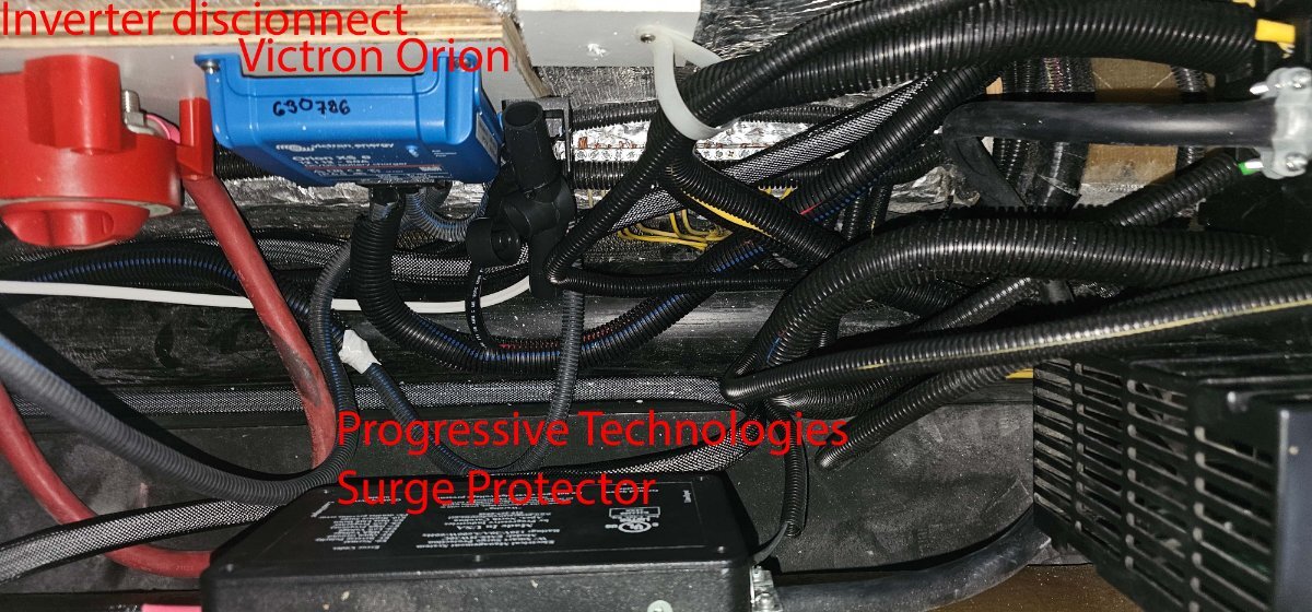
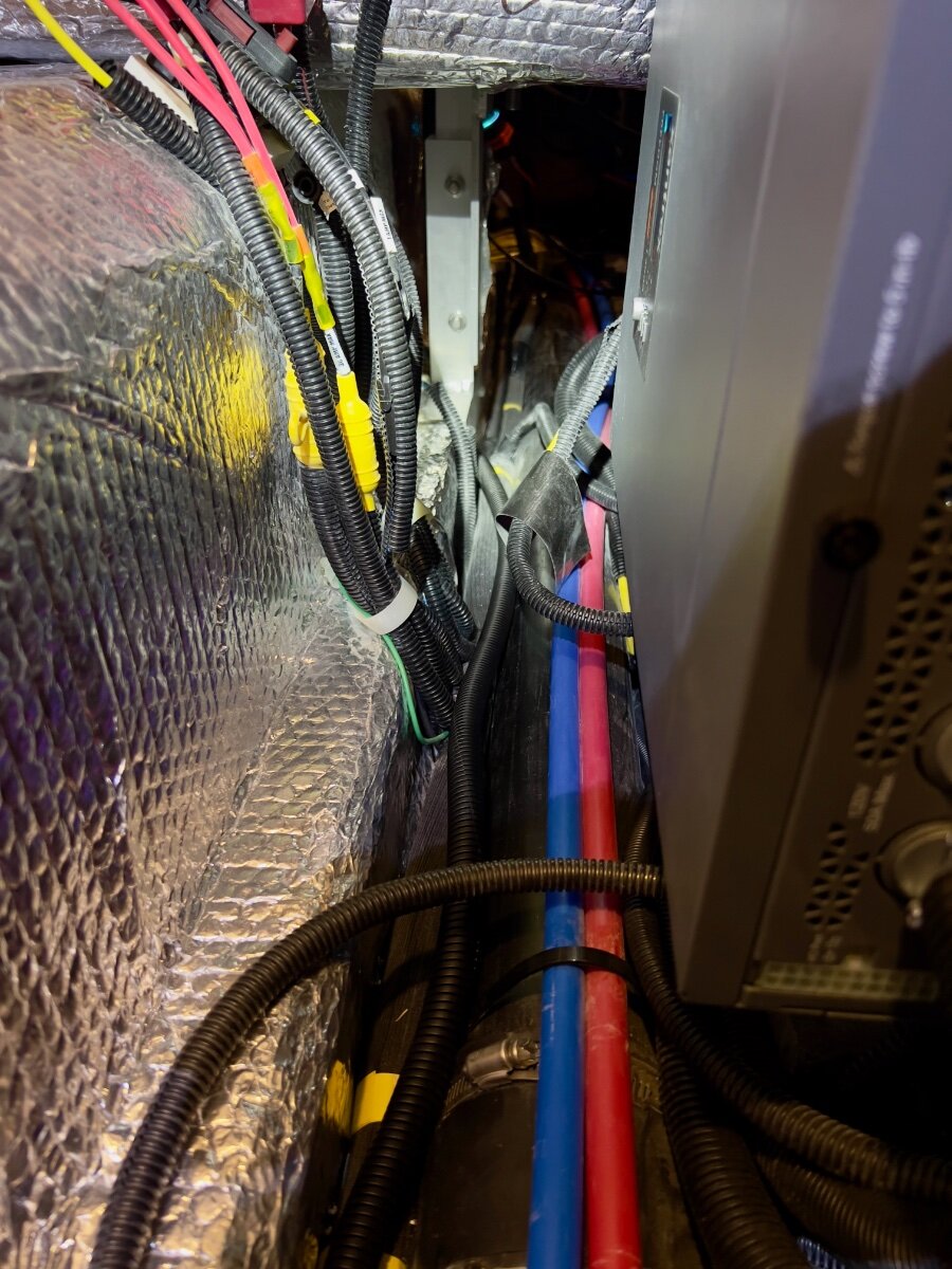
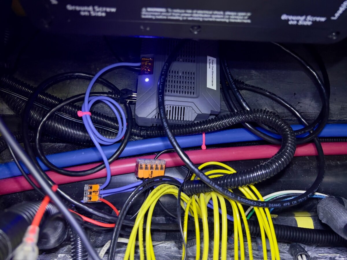
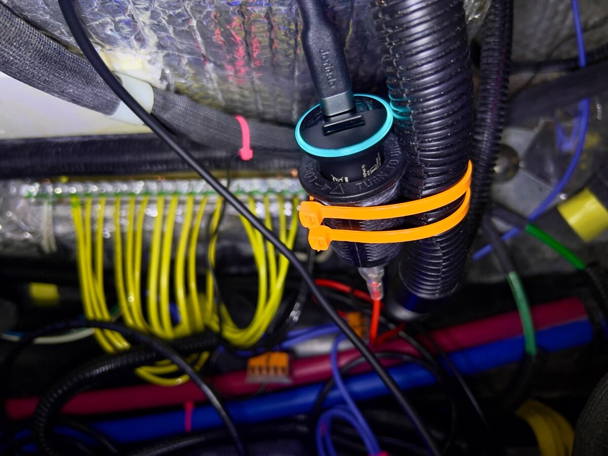
On a recent trip from Dallas to South Carolina we stayed in multiple locations with no (or very limited) communications capabilities (cell phone or WiFi). Over the three years we have owned our LEII, there have been many other occasions with no ability to communicate. As a result, we decided to order a Starlink Mini and a Starlink Router Mini to use on our trailer trips. I have been following Starlink related postings on the OTT Owners Forum, especially since the release of the Starlink Mini. I have found the postings by @Snackchaser particularly helpful in planning the installation of our Starlink system. I especially liked the use of a Power over Ethernet (PoE) injector to power the Starlink Mini and to provide an Ethernet connection from the built-in router back to the trailer, using a single cable. Installing the PoE injector and a DC powered router in the attic of the LEII seemed a reasonable location, being nearly directly above the exterior Furrion ports for connecting satellite and cable TV. So I planned to install in a similar location in the attic of our LEII, assembling a list of the components required. I ordered a PoE injector from MobileMustHave.com and the rest from Amazon. Once all the key components had been delivered, I began the installation, with the first step being to replace the Furrion Satellite coax port with an RJ45 pass-through connector and to fish an Ethernet cable from the basement to the attic. Replacing the Furrion coax connector with the RJ45 pass-through connector was no problem, even though enlarging the hole through fiberglass exterior shell was required. However, fishing an Ethernet cable from the basement to the attic proved to be a major obstacle. Although I have prior experience fishing wires through difficult spaces, I was unsuccessful getting a fish tape (or rods) from the attic to the basement. I could get the end of the fish tape rods down near the ceiling of the basement, where the interior shell ends and multiple cables run up to the attic area at the rear of the trailer, but not into the basement. As suggested, I tried following the A/C drain line and multiple other locations but could not get past the bottom of the inner shell into the basement. I tried running the fish tape/rods in both directions. No luck. Consequently, I began to ponder other installation locations inside the trailer for the PoE injector and Starlink Router Mini. After a couple of days, I had an Aha! moment- install the PoE Injector and Router Mini under the rear dinette seat. I inspected the space between the basement and the rear dinette seat, nearly all of which is readily accessible from the two rear street side hatches and the rear dinette seat hatch. Only the space under the battery compartment is not accessible from directly above, but is easily accessed from either side. I looked for any obstacles to using this location and found none. I could easily route the Ethernet cable from the Furrion/RJ45 pass-through connector forward to beneath the rear dinette seat. I located the PoE Injector atop the trailer frame member, just below the Progressive surge protector box, which is mounted on the aisle wall of the rear dinette seat. The PoE jack and the power terminals of the PoE Injector are positioned toward the front of the trailer. I connected a 20 foot shielded Cat 6 cable from the inner side of the Furrion/ RJ45 port, then routed it under the floor of the basement, around the street side rear stabilizer, then following the waste water line, forward to the area under the rear dinette hatch. About 3 feet of excess cable are coiled in the basement, concealed by the rear wall of the basement. I installed a lighted rocker switch through the forward basement wall, mounted high, almost directly above the side-to-side bubble level on the left side of the basement entry. This switch is to control 12VDC power to the PoE Injector and the Starlink Router Mini. Using 14 AWG silicone coated wire, I ran two purple colored wires from the space beneath the rear dinette hatch back to the rocker switch on the forward basement wall. A third, 14 AWG black wire was also run along the same route to the rocker switch. The switch has two terminals with red lead wires,: one to the DC power source and one to the load. The third terminal has a black wire, which connects to ground (the bus bar). The ground wire enables the light on the switch to operate when DC power is ON. On the DC power panel, position 15, I installed a 15 amp fuse. One of the purple wires connects to the 12VDC positive terminal on the PoE Injector. The other purple wire connects to position 15 on the rear of the DC power panel, using a crimp on connector. The single black wire from the switch connects to the ground bus located under the rear dinette seat. Another 14 AWG wire connects the PoE Injector negative terminal with the other end connecting to the bus bar. All wire-to-wire connections were made using Wago lever lock connectors. I also added a 12VDC auxiliary power outlet (cigarette lighter type) which is connected to the same circuit as that which powers the PoE Injector. An Anker 323 USB-C Car Charger Adapter (USB Power Delivery (PD) capable) plugs into the auxiliary power outlet. A USB-C to Male to DC 3.5 x 1.35mm Male Power Jack is used to power the Starlink Router Mini from the Anker charger. I found the Starlink Router Mini conveniently fits on top of the Progressive Surge Protector box. I later secured it with a releasable zip tie around the surge protector. The 20 foot Cat 6 Ethernet cable from the rear connects to the PoE jack of the PoE Injector. A 5 foot Cat 6 Ethernet cable connects to the LAN jack of the PoE Injector and to the WAN/Satellite port of the Starlink Router Mini. All Cat 6 Ethernet cables used are shielded. I believe this installation location approach has several advantages over an attic installation: Access is MUCH easier. Fishing wires is no challenge. A dedicated circuit from the DC power panel provides power to all Starlink related components. A lighted switch for the PoE Injector and Starlink Router Mini is located in the basement, near the exterior pass-through Ethernet jack. The PoE Injector is located where it cannot be covered by clothing or other cargo stored in the attic which might cause overheating. The VERY bright blue light on the PoE Injector is not visible in the cabin (always ON if power to the PoE Injector is ON). The Starlink Router Mini is located centrally in the trailer and should provide uniform WiFi coverage within the trailer. We have not yet taken the Starlink on a shakedown trip, but plan to do so at the end of August. Regards, Don
-
 Does anyone use a single or dual unit instead of using the propane stove?
 -
Everytime I pull out my faucet to shower. I lose my water pressure. Is this normal? How can I fix this?
-
 Can I tow an Oliver LE2 with a 2006 Toyota Tundra Double Cab? I have a first generation, 4x4,Tundra SR5 with a 4.7L V8 engine, and the Tow Package that includes the oil cooler and upgraded alternator. I ascend (and descend) the Pacific Northwest mountains. The truck has a an aftermarket electric brake controller and an Andersen WDH. Tundra Specs from Owner’s Manual: GVWR = 6600 lbs. (2994 kg) GVAW Front =3500 lbs. (1588 kg) GVAW RR = 3760 lbs. (1706 kg) Max Gross Trailer Weight = 6700 lbs. ((3039 kg) Hitch Carrying Weight = 670 lbs (304 kg) Max Cargo Weight = 600 lbs. (272 kg) Oliver Specs: GVWR = 7,000 lbs Dry Weight = 4.900 lbs Tongue Weight = 490 lbs. Looks like the DRY weight of the Oliver (4900 lbs) is little below the "80% Towing Rule" with 460 lbs to spare. (Tundra Max Trailer Weight= 6,700 lbs x .8 = 5,360 lbs.) However, the GVWR weight of the Oliver (7,000 lbs) is 300lbs more than the Tundra's Max Gross Trailer Weight (6700 lbs). Assuming that I add air bags and beefier brakes to the Tundra, can I safely tow an LE2? Thanks in Advance,
 -
My Oliver is a 2019 Elite ll. I have tried to get my fridge repaired at the Oliver service center in Hohenwald. They said that they couldn’t get parts for it and quoted me 4800.00 dollars to replace it with a 12 volt compressor model. I thought that was a very high price so I am reaching out to you good people on the forum. Have any of you had this issue? Thank you.
-
Anyone have any idea why my water pressure is dropping off. I suspect it might be calcification and may need a vinegar cleaning. Anyone had this problem or a bad water pump? 2017 elite 2, 415 days of camping/usage 😊
-
This spring I ordered new Dexter Nevr-Adjust brake assemblies and new pre loaded drums for a 60k mile tune up. Since the trailer was at a dealer for the truma recall had the dealer install them. We had some smoke early on during break in drive was expected, stopped checked temperature of hubs and all was ok. Set gain to 5 and drove on. After the break in period at about 300 mi we were feeling really strange tugging braking. Stopped at our daughter’s ranch, pulled the drivers side hubs and found the brake pads had just disintegrated. The service centers best guess is that the self adjusters over adjusted and caused brake lining failing or we unfortunately got a bad batch. Lucky we were near a local shop that got us in Saturday and replaced all 4 assemblies with regular assemblies (not never-adjust) . They also inspected, turned the drums, repacked bearings and installed new seals. We’re working with e-trailer to get a refund as the assemblies had a 5 year guarantee. Now I’ve added an item to our 3k inspection which includes lubing Zerks, and now adjusting brakes as needed. I’ve heard of, but never experienced, failed never adjust, but now I’m in the camp that they are not welcome on our trailer. First pix note the crumbling shoes curb rear. Second pix- shoe all gone to bear metal. Had to turn drums (which were brand new). Street rear. Safe travels. Craig
-
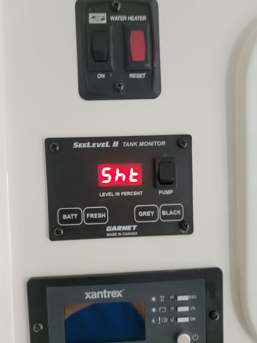
just unplugged from shore power. Herd some beeping alarms. Lots of weird numbers flashing on the sea-level ll tank monitor. xantrix is blank. We assumed our lithium batteries were fully charged after being on shore power for 2 days. I think this whole inverter etc is just too complicated for me. there is no reason any owner should have to ynderstand this. I assumed this syst was idiot proof. It is not.
-
I sent a message asking the folks at RV Trip wizard if they had a feature to overlay multiple trips on one map...and they said no but to try exporting to Google Maps and using layers....here's a result as an example of what's possible, I'm still learning. So Google Maps allows direct import of the .gpx files that are output by RV Trip wizard. Normally the .gpx are used to load into Garmin devices, but Google Maps reads them as well. I started by opening up a new map in Google Maps created "My Map" as a BASE map with the first 2019 trip where we picked up the trailer, and added a layer for each subsequent main trip. I found that 6 is the maximum number of individual layers you can add in Google Maps. There are controls to change the type of marker, color, line width etc. There are also controls to turn on/off the titles for each stop. To create more graphic maps, Google enables embedding photos by geotag into the maps as well. I'm considering adding pictures of each campsite for each stop to see if it's at all useful. The map below lets us see big holes in our travel...so we've still got miles to go before we sleep! Craig & Rose Hull 505 - Galway Girl
-
With the number of "bandito posts" on other's A/C topics (Such as the Truma threads), I figured that a separate post for those retrofitting their Domestic's to the Houghton A/C units would be in order. That way the Truma Team won't have to listen to all our interruptions on their threads. 🙂 It would be wonderful if our moderator(s) could relocated the many bandito posts (such as mine and others) to this thread. And God bless our moderators. Mahalo, GJ
-
Hello all mew owner of the first Oliver sold new in Canada. Looking forward to a 10K trip planned in late May early June. I’m wondering if any one out there has done post delivery Natures Head install on the LEII. If so would appreciate some tips. Thomas J
-
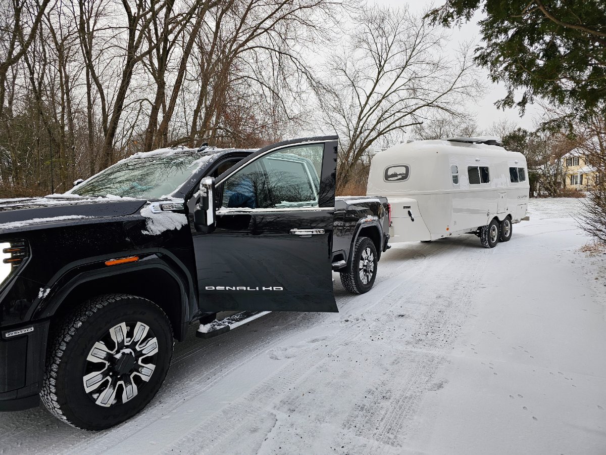
We are the new owners of Piccolino (original name as we have not yet had a decommissioning/recommissioning ceremony with appropriate amounts of rum to change the name) hull # 1346 and are on our inaugural trip from MA to Mayport FL. We had a fabulous experience with the previous owners and are thrilled with our new rolling nest and our new tow vehicle aka The Beast, 2024 GMC 2500HD Denali using the Gen-y Boss hitch. Jason and Kelly were so helpful as we marched up our learning curve in towing and Oliver's. This forum has also been a great source of information, thanks to you all. So far, our tow experience has been great, feeling very stable and at ease underway. Our first two nights saw temperatures down to 14F and we remained warm and dry. Unit is winterized with composting head so no worries for frozen lines. We have previously owned a 2016 J Navion and a 2019 Tiffen 34PA and are finding our Oliver to be so well designed, engineered and manufactured. But I have to admit, I still need to understand how the toilet paper holder is designed! See you on the road!
-
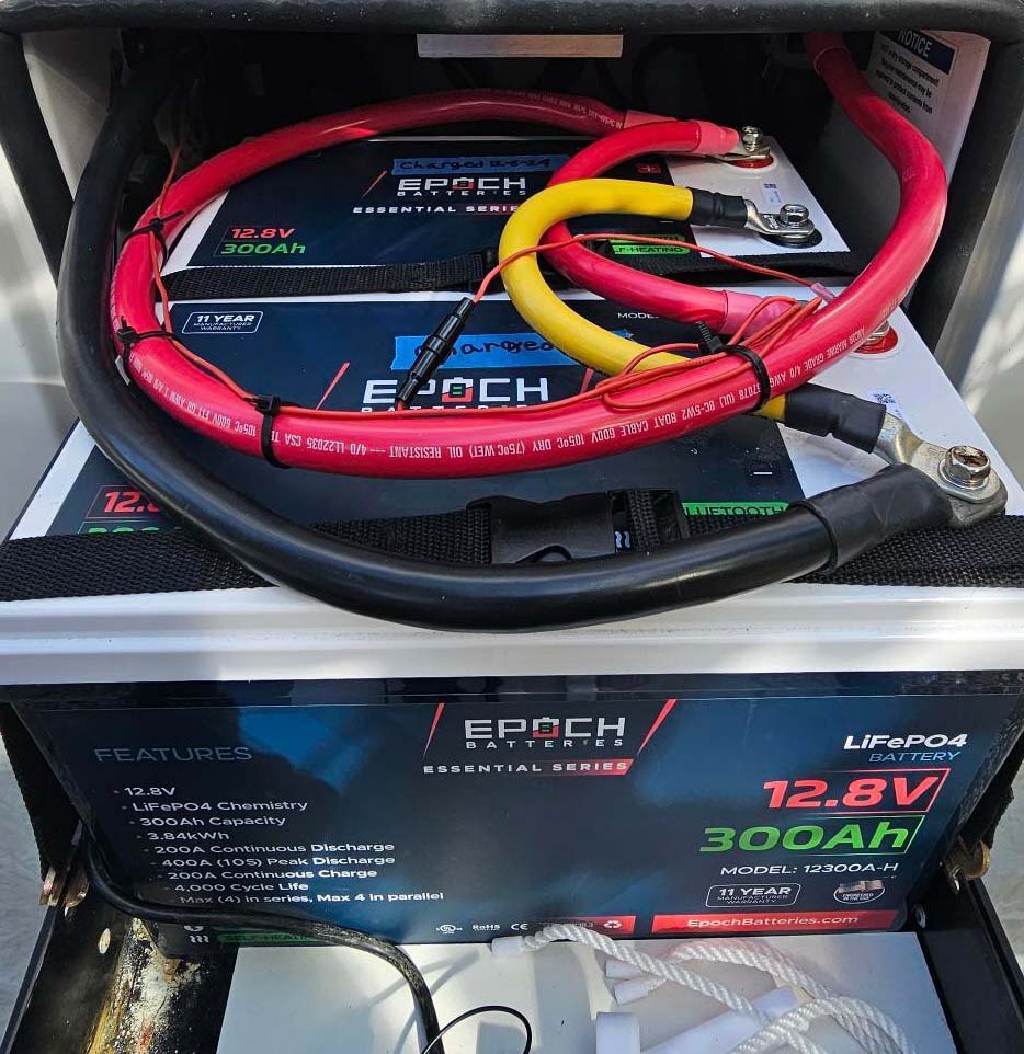
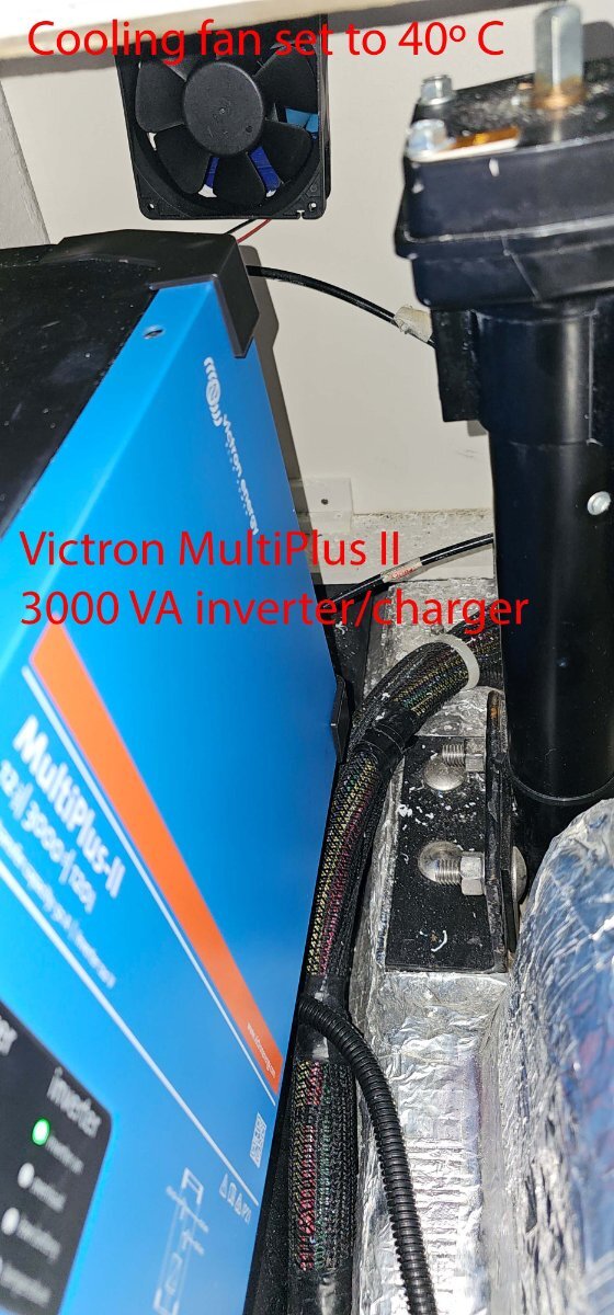
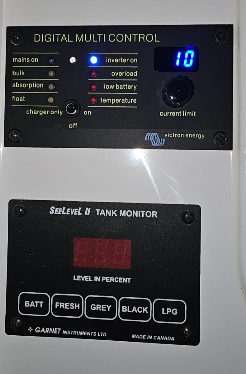
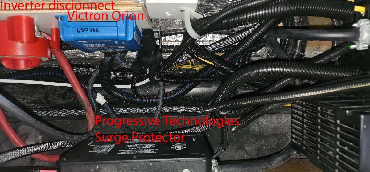
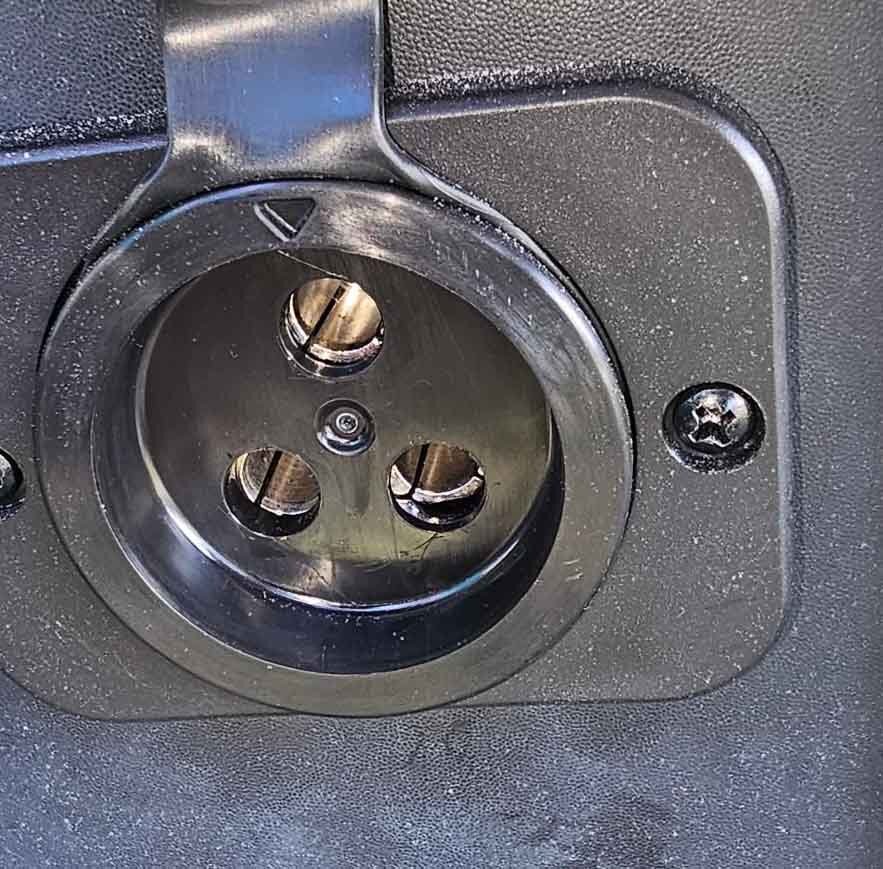
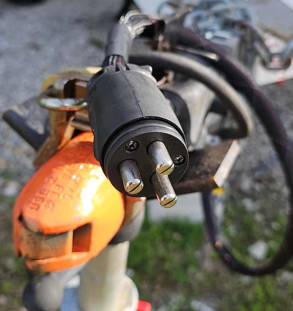
Overview We just got done upgrading our 2018 LEII (hull #344) from AGM to Lithium. The death knell had sounded for our original AGM batteries. So, given the cost to replace the AGMs, their weight, and the limited usable capacity inherent in AGMs, we decided to upgrade to lithium. We settled on 2, Epoch 300 Ah LiPO4 batteries with internal heating (a total of 600 Ah). The decision to purchase the Epochs was made easier by a 15% sale so we bit the bullet and purchased the batteries , a new Victron Multiplus 2 3000 VA inverter and charger, and a Victron Orion DC to DC charger which will allow us to charge directly from the tow vehicle. Here are more specific details about each step. We relied to a great extent on our tech. Victron Orion DC to DC charging We mounted the 50 amp Victron Orion under the aft seat in the dinette. The Orion was set to draw 30 amps from the alternator on the 2020 Ram 1500 Ecodiesel tow vehicle. The alternator puts out about 220 amps so we are confident this is well within safe operating parameters with all existing loads. We used 4 awg coupled to a marine connector from the TV to the trailer which looks to be quite robust. Of course, we disconnected the power from the 7-pin connector. Victron Multiplus 2, 3000 VA inverter and charger We mounted the inverter vertically under the streetside bunk. We also added a dc fan onto the bulkhead between the bunk and the basement to address heat issues and set it to operate above 40C. The inverter has a main disconnect as well as an inline breaker as per code. System Monitoring A Victron Multicontrol replaced the Progressive Technologies inverter switch from the OEM install and was installed in the same location. This is our primary control panel which provides operational status of the system, and allows us to control the input current. Specific battery State of Charge and other more granular data are available in the Victron shunt app, the Epoch app, and the Victron Multiplus app (as well as the original Xantrex Solar Controller which we did not change). Performance of the system We tested the system today by running our OEM Dometic Penguin A/C off the battery bank. We set the thermostat to 75 F. After 5 hours, we were at 55% SOC. Full disclosure, we only finished the install today and the tests were conducted in our winter conditions here in the Keys at 78 F ambient. The trailer did get warm during the day, but I do think we are likely to get 5 hours or so of A/C in the hotter summer months. Maybe even more. We haven't tested the DC to DC other than at idle. As mentioned, we set the charger to 30 amps so we are likely to get a full charge after a full day driving but that is just an estimate. We have enough leeway to turn up the output from the alternator if needed. Special KUDOS A great deal of thanks goes to our tech who helped install all this - Anthony from Outboard Rigging here in Marathon is the Man! Pictures of the install follows:
-
 We have been trying to connect the tv so that we could hear it through the sound system to no avail. Checked you tube and owners manual. Seems simple but we cannot make it work. Thoughts?
 -
 Hi, about 3 weeks ago I purchased a used 2022 LE2 with the Lithium Pro package. I've searched for the answer to this question here and in other places, and have a suspicion, but I thought I'd ask the experts here before I start making expirimental changes just in case someone can tell me for sure what is wrong. The issue I'm having is that the three lithium batteries, which appear to be in good condition, do not charge and discharge together simultaneously. So, if I'm using a load, one battery might report that it is dispensing 20 amps, and the other 5A and the third might be 1A. Eventually they will all become discharged. The same is true in reverse, when they are charging, one will receive more amps than the others and reach full charge first. My suspicion is that the wiring of the batteries is not correct, from what I've learned from watching YouTube videos about RV lithium battery set ups. My understanding is that the batteries are supposed to be wiried in parallel, with diagonal take offs. There appear to be four different take offs in my setup (I haven't figured out what each one is yet, but I'm guessing one is for connection to the Xantrex Inverter/Charger and one is for the battery pad heater, but I'm haven't figured out what the third and fourth are). It looks like the pad heater is the one that is not connected properly. However, I find it odd that the problem exists whether the heater is on or off. Note that I don't believe the previous owner changed anything (the marks on the cables and terminals would indicate that also), so it was almost certainly set up this way at the factory. I've attached a photo of the cable connections to the batteries, and I would be happy to make another post with photos of the Xantrex settings or the Lithionics battery app information if anyone would like to see that. Thanks in advance for any help you can provide! Paul
 -
Given the coming changes to the Oliver service model, I was thinking it would be nice to be able to communicate with other Oliver owners who are local. An Oliver-ownership registry could be a completely voluntary opt-in sort of listing that would allow nearby Oliver owners to connect offline. In my particular case, it would be nice to share info about trailer servicing locally/regionally. There are no recommended Oliver dealers in my state and the nearest one is 400 miles away. Is there any interest in this concept?
-
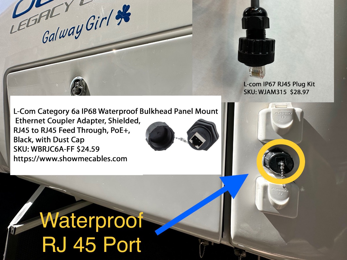
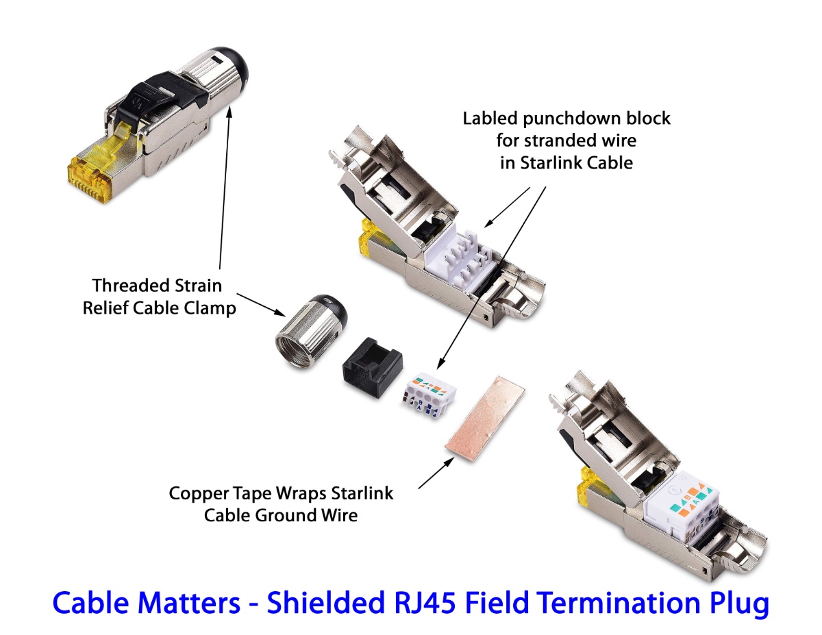
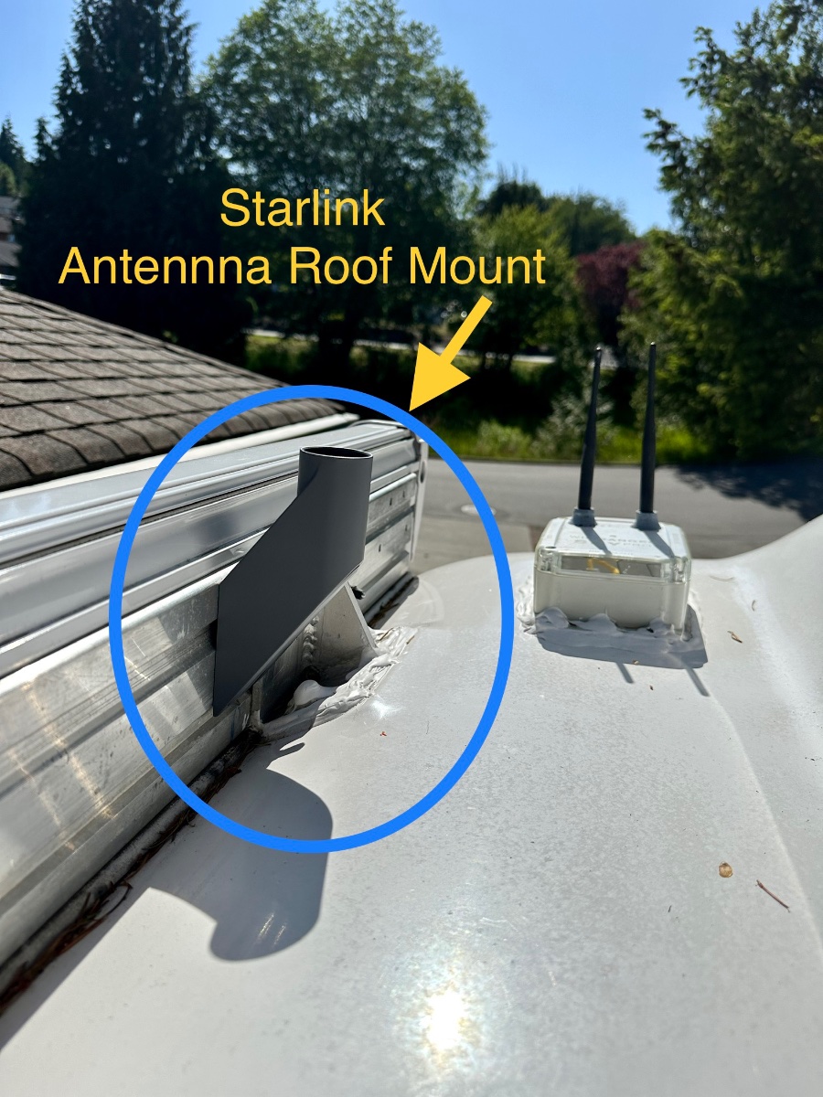
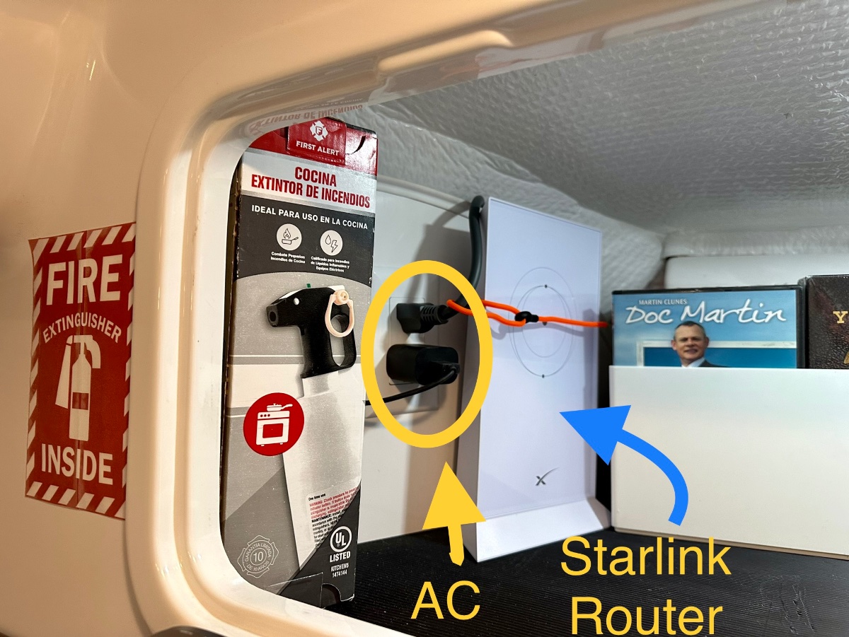
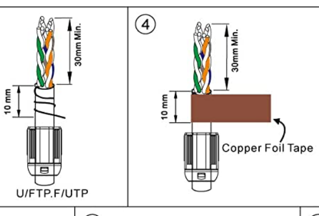
After looking at the forum I found a couple posts on installing Starlink. I decided to add another to the mix. Pre-Installation Starlink Test: In testing the system before a full installation I found that the Starlink Router could be plugged into curb side Oliver outlets and then the router could sit on it's back on top of the tire under the wheel well. This provided 58dB of signal outside the trailer and about 78 dB inside. So if you don't want to hassle with mounting the router, drilling holes etc. you could just find a weatherproof box/cover for the router and leave it outside. (Signal strength and bandwidth drops a bit but not really very much.) Read on if you want to do a more complete installation. 1) Roof Mount: (This is just a way to mount the antenna up high.) I bought the Starlink short roof mount adapter. Our hull 505 had the Dometic Awning, so I could not simply bolt directly to the mounting bolts from the awning brackets as they are at odd angles. I used 1/2" long x 3/8" diameter Self Tapping Bolts. I drilled holes, then drove in the self tappers into the mounting rail making sure to use washer/spacers to keep it from penetrating the back of the awning box. I used blue loctite on those tapped bolts. This mounting position will be perfect in those cases where we have clear sky and want the antenna up high. I'll continue to carry the ground mount for portability uses. I don't plan to drive with the antenna on the roof. 2) Mounting the Router - In the Rear Attic and Running Cable into Basement I mounted the router inside the rear attic cabinet. It's held in place by a simple orange strapping tie that feeds through a hook-eye behind the router. This is a good spot for the Router as it's close to a 110V outlet, and easy to run the cables under and behind the back of the cabinet over to the right side then down to the basement area. To make the cable run to the basement I needed to remove a couple panels: (NOTE: DISCONNECT FROM CURB POWER and make sure Inverters are OFFLINE BEFORE ATTEMPTING) 1) Street side attic panel (2 bolts) tip it down flat to gain access to the street side rear of the cabinet. 2) Basement rear dress panel covering the back the basement. (2 phillips screws). For my installation I ran the cable beside the existing AC drain tube on the street side rear of the trailer. I pushed the cable snake down beside that tube, and then at the bottom in the basement attached and I pulled up a length of pull line from the basement area. I attached the pull line to the end of the Starlink cable (the end that plugs onto the dish) and then pulled the Starlink Cable down into the basement. I tested the Starlink at this point before cutting the cable to get a baseline of speed for comparison after I cut the cable and attached RJ45 network connectors and the thru hull port. After testing I looped up about 3 extra feet of cable in the basement and then cut the cable for installation of the RJ 45 connector that would feed the back side of the thru-hull RJ45 plug. 3) Install new RJ45 male plug on cable in basement: Pro TIP: Use metal field termination plugs for the Starlink cable cut ends if possible/ Trying to use the typical plastic RJ45 connectors is a real hassle as the conductors in the starlink cable which stranded and thicker than normal. I spent well over an hour trying to get my shielded/plastic RJ45's to work. I finally said let's try a real metal coupler. In the picture below is the plug I bought from "Cable Matters" on Amazon $6 ea. They feature a clearly labeled punch down block, a threaded strain relief clamp and copper foil tape that is used to wrap the ground (or drain) wire around the cable shaft where it enters the connector. This is the connector I used on the inside of the trailer connecting the Router to the Thru Hull plug. 4) Install the Thru Hull Connector and connector for Cable to Dish I purchased an L-Com IP68 (waterproof) through hull connector specifically designed for shielded PoE Connections. I also purchased a matching L-Com connector kit for the cut end of the Starlink cable. This matching plug screws onto the outside connector for a waterproof sealed connection. I placed the connector mid line between the two existing connectors leaving both the Cable and Satellite COAX's in place. The new bulkhead coupler fits exactly between those two connectors, but I would suggest shifting UP 3/16" from center to allow the bottom door to fully open. (It's the 'satellite coax' in my case which I never use.) Hope this is useful to any new Starlink owners. More detail is in our blog here: Adding Starlink to Galway Girl Craig Hull 505 - Galway Girl











.jpeg.bc5410dca345743218c7cdd61cd7a837.jpeg)
.jpeg.db24308a47698837a565fc55eec3a655.jpeg)
.jpeg.b601f1e7eac4638423f2297d1cfed3e5.jpeg)
.jpeg.799f3cf194b3b21d05b2a7bb19f728b1.jpeg)
.jpeg.dd379fc2e5087fa6910ce21b437441ad.jpeg)
forPoEInjector.jpeg.2ff4c7b3725adaf25e5bdfc30965ceff.jpeg)
atopProgressiveSurgeProtector.jpeg.5c03a313182d5fdb47bf1a254dec329d.jpeg)