

Ronbrink
-
Posts
495 -
Joined
-
Last visited
-
Days Won
5
Posts posted by Ronbrink
-
-
12 hours ago, rideadeuce said:
I still have not worked out the kinks on my DC/DC charger setup, averaging 11-15 amps on the road. So nowhere near the potential of the 50amp charger.
You may want to consider replacing the stock alternator with a high output unit. I started running into trouble when I swapped out the Renogy 20A DC-DC for a 40A, same brand. At idle, the Renogy was only providing around 25 amps and the TV battery was not being properly maintained. When using the A/C via inverter during brief stops, I generally keep the TV running so the DC-DC can augment the power consumption of the A/C; this has proven to be detrimental to the vehicles charging system! Also, I have issue in stop and go traffic when transiting cities. When running at speed, I get full charger output, but the alternator struggles to keep the TV’s battery appropriately charged. I recently purchased a 320A alternator (at high rpm) to replace the stock 165A, which produces 200 amps at idle; awaiting delivery of supplies needed for the install.
-
 1
1
-
-
3 hours ago, jd1923 said:
I was thinking what can I use to slow aluminum oxidation after such deep sanding?
If ever the times comes, I would consider having mine powder coated.
-
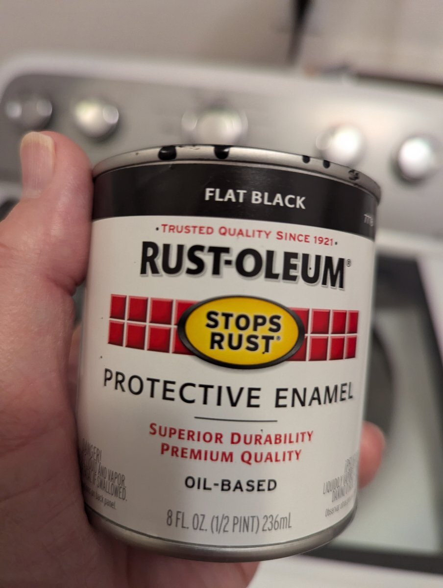
23 hours ago, John Dorrer said:
This is what we use, and a small can and a couple of small brushes.

👍 Their Oil-Based is the best for rust prevention and adhesion, based on my experiences! Next up, Rust-Oleum Professional spray cans.
-
5
-
-
On 7/7/2024 at 7:30 PM, Donna and Scott said:
Here attached is the list of attendees. If I have missed someone, please let me know.
Please add to your list: Ron and Brooxie Brinkley, Hull #579, Hull Name My COW, Site #227. Thanks
-
3
-
-
On 7/7/2024 at 8:06 PM, jd1923 said:
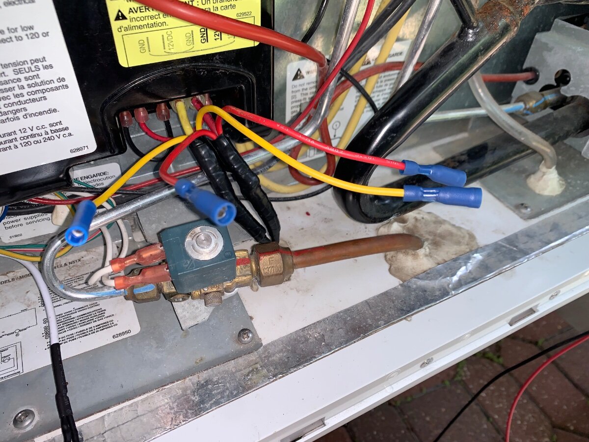
I'm thinking of running new 14 AWG automotive wire (I have spools) from the junction down below (mine has a junction that I do not see you your pic, I will show later) up to the switch in the light panel and then back down to the upper vent area for the fans. This way I still have the switch, all new wiring and the junction down below looks like 8 AWG, at least 10, and it showed 13.6V.
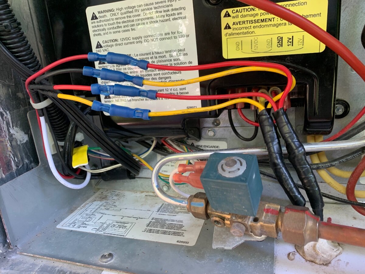
I am familiar with the small terminal block (“junction”) you are referring to, mine uses spade connectors to make power wire connections to the Norcold’s power box (seen with the white and yellow labels in pic). In my install, I disconnected the two power fed lines Oliver routed (10 AWG) into the lower exterior fridge compartment, being the two wires shown wrapped in electrical tape. Rather than cutting these wires to make a splice, I choose to strip a 1/4” length of insulation off each, whereby the wire strands could be separated enough to loop 6” pieces of wire (red +/yellow-) through, that also had insulation removed (5/8”) at its’ midpoint. Once inserted, these wires were simply folded in half, then twisted to join at the bare wire junctures and subsequently soldered, heat-shrink treated and taped. Then these two added power leads were respectively connected to the control panel and fan wires via quick-connect terminal crimp fittings. I did however, have to splice a short piece of larger gauge wire onto the control panel wire ends because they were too small for the QC fittings used. The 14 AWG wire you have should be of sufficient size for your fan mod.
-
1
-
-
@SeaDawg, I’m liken’ my 3-way Norcold more and more!
-
3
-
-
10 hours ago, jd1923 said:
Question: do you use the Beech Lane controller much? Wondering is after you get it where you want it, does it need to change. Hoping you don't need to mess with it much, and if so i may install it behind the lower vent opening.
I cannot provide an answer since the Oliver has not been used since this mod. I did however, want easy access to the control panel from the inside, thus the upper cabinet install. I have read where some leave their’s On continuously in Auto mode, I plan to have it turned Off when in storage. Never attempted a link, but can provide a pic of a post you can search. If you haven’t seen, It is very informative and discusses use of a switch at the entry panel, as well as user impressions and comments.
-
 1
1
-
-
5 minutes ago, John Dorrer said:
Thinking you could wire to the street side awning switch, if you don't have the street side awning.
I have is a blank where that switch would typically go. That said, one could add a switch to serve purpose of powering the fans and control panel. However, the control panel acts as a switch in similar manner.
-
2
-
-
15 hours ago, jd1923 said:
So, the easy fix for $90 is to replace this fan with the Titan or Beech Lane dual fans that other owners have done. I would not be able to use the switched power since it is not delivering 12V. I could run new wire from the junction below. In AUTO mode do these turn on-n-off with temp? I would mount the control box behind one of the panels, not in the upper cabinet as one post showed unless it can be fished there w/o going through the microwave cabinet, as I just insulated that cabinet for an oven. Can the ON/OFF temp settings be adjusted on these? I would hate to bypass the switch. Maybe I can run +12V up to the switch panel and back down. Any ideas are appreciated as always! Thanks
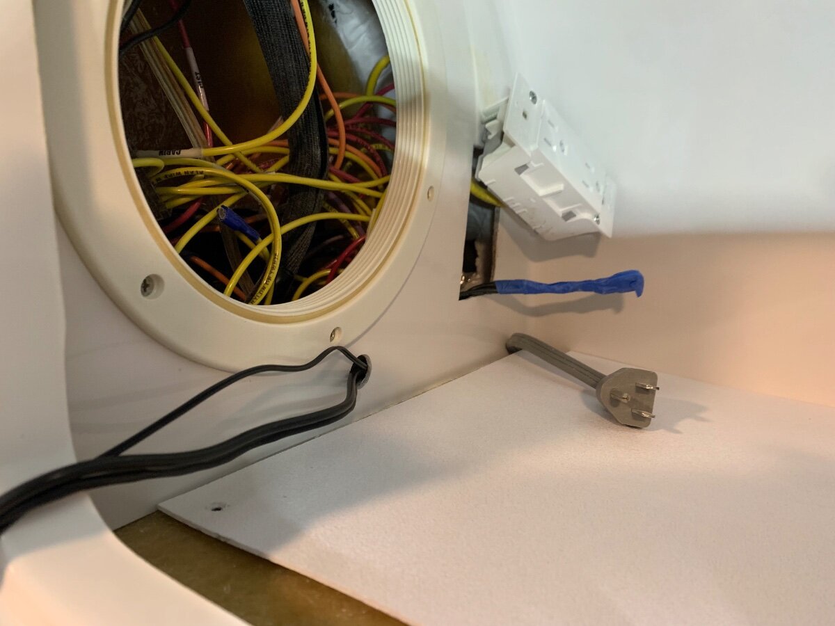
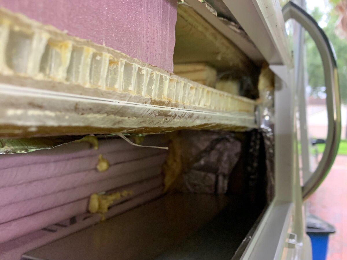
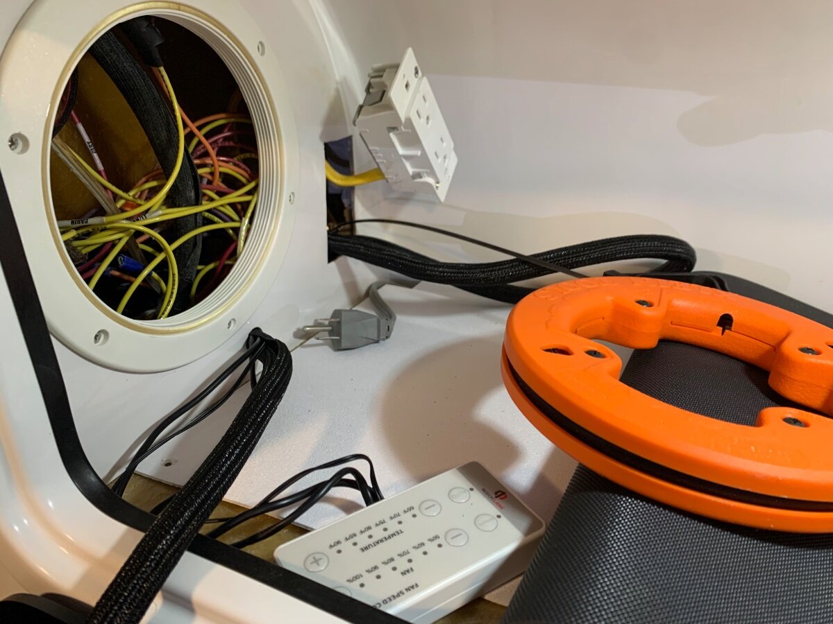
I recently installed the Beech Lane dual fans and was able to run wires from the interior cabinet, above the microwave/Norcold, down and behind both units for the fan control panel/harness and power connections in the upper and lower exterior vent/cover areas, respectively. Access for fishing the wires required folding back the cabinet’s protective mat liner, removing the round access port cover and detaching the AC outlet box (after turning power off at the breaker) that the microwave plugs into, as well as drilling a hole (see pics). Additionally, I had to remove the foil tape and angled aluminum plate that occurs behind the upper exterior vent/cover to enable the wire fishing process; specifically, the fiberglass divide between the two units inhibits passage wherein a visual and physical interaction may be necessary. Regarding your wall switch, if you could get 12V power of appropriate gauge wire to it, then power wires would not have to be fished down to the lower reaches of the fridge for connection.
Steps taken in prep to fish wires. There was a passageway found inside the outlet cutout to the lower right, other side of the interior cabinet wall from the microwave power cord, leading to the upper exterior vent/cover area
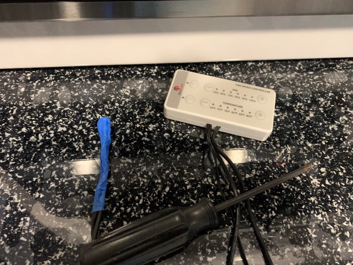
Control panel wires prepped for fishing.
Wire loom installed during stages of fish process.
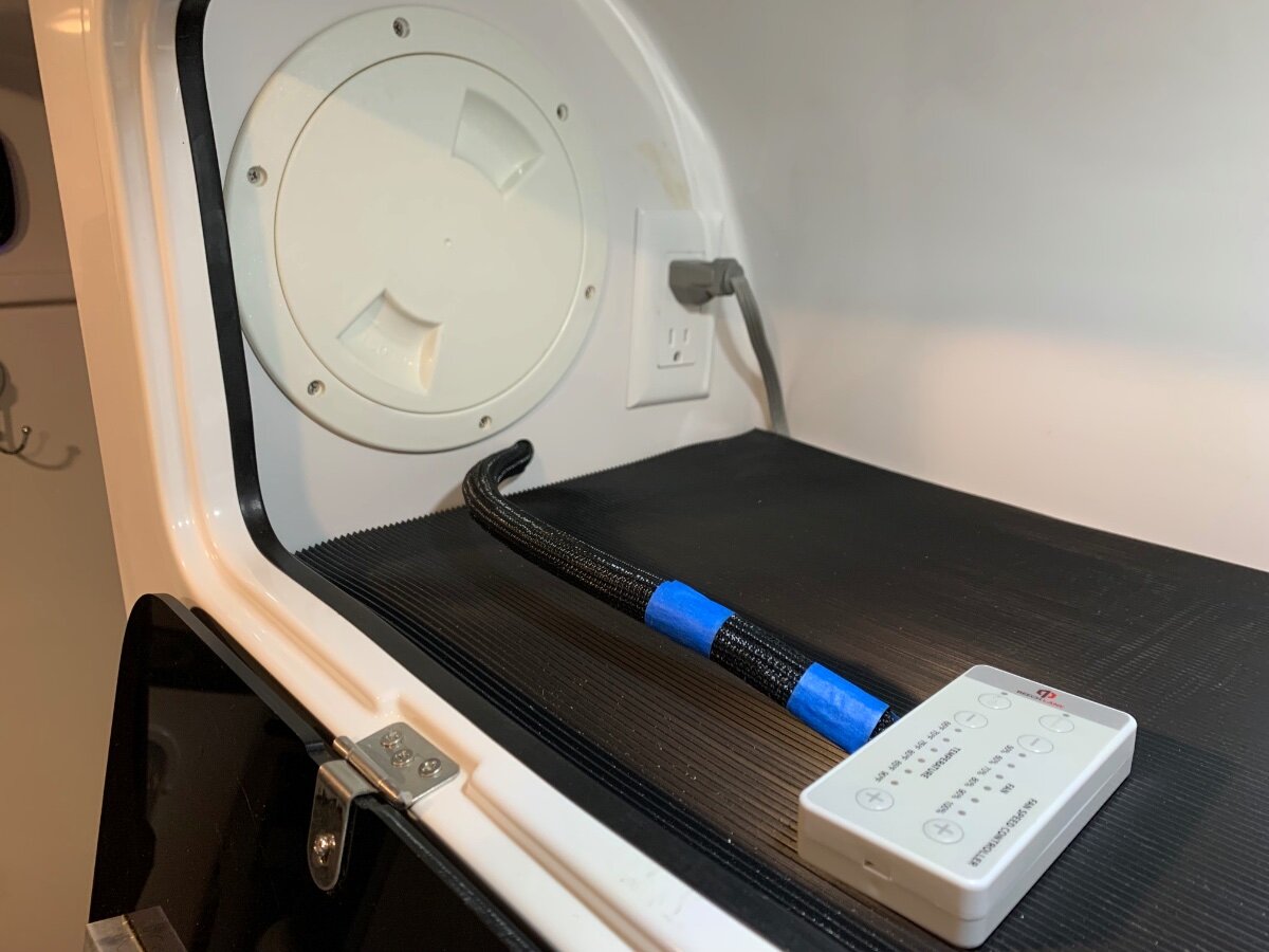
Routing completed to upper exterior vent/cover area.
Interior cabinet buttoned up!
Quick connects used at 12V power connections.
-
2
-
1
-
-
9 hours ago, ZLarryb said:
I did turn the collar but did not depress the thumb level, that could be it, thanks so much for all the responses, I will give it a try in the am and let u know.
To be clear, the thumb lever on the LockNLube coupler, affixed to your grease gun, will be depressed when attaching the 90° extension to ensure the two components are properly joined; then the adjustable collar at the end of said extension is turned one way to tighten its’ jaws to hold onto the zerk for a good seal and the other way to loosen the jaws for removal from the zerk when done. Many owners simply replace the stock zerks with 45° and/or 90° angled ones to eliminate the need of the adjustable extension.
-
3
-
-
On 7/4/2024 at 10:28 AM, ZLarryb said:
I am using the LockNLube grease gun with the 90 degree fitting.
My previous was pertaining to use of the primary coupler with the thump lever, but since you are using the 90° adapter one must turn the adjustable collar that goes over the zerk to lock it in place and then turn in the opposite direction for ease of removal.
-
1 hour ago, ZLarryb said:
I have gotten about half to respond, I think it is a good suggestion to depress the zerks that are not accepting grease. I think u are saying that all the zerks are the same. - of course - and there is only one size fitting? I have not replaced any zerks, only tried another grease gun attachment, thanks
Are you depressing the thumb lever to open up the four jaws? Upon release the coupler should be locked onto the zerk, and should not leak or come off until the lever is depressed again to remove.
-
3
-
-
On 8/4/2023 at 9:52 AM, Rivernerd said:
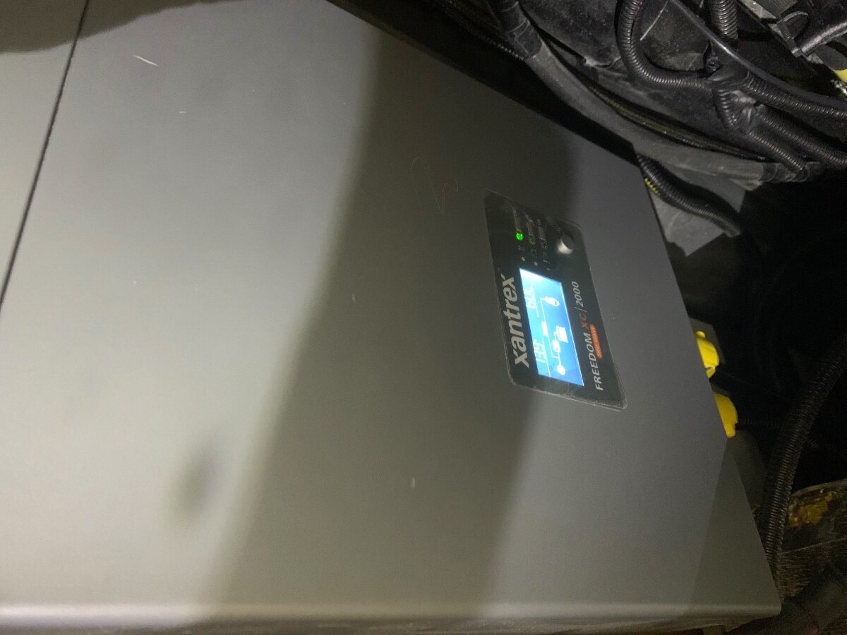
It appears to me that setting the LBCO at 11.5V compensates for the fact that, when under heavy load, our inverter misperceives the actual battery voltage by as much as 0.9V (12.7V actual -11.8V perceived=0.9V). It still concerns me that our Xantrex inverter misperceives DC voltage when under heavy load, but this new "workaround", i.e., setting the LBCO artificially low, enabled me to run heavy wattage loads on inverted power even at lower SOC levels, as the system was designed to do.
With the LBCO set at 11.5V, even though the Xantrex inverter perceived DC voltage of 11.8V, there, of course, were no inverter shutdowns or LBCO "[01]" warnings. With that setting, it appears we can use high-wattage appliances on inverted power at least down to 22% State of Charge (SOC). This is encouraging.
I lowered the LBCO from 12.1V to 11.5V and that did indeed allow extended use of the A/C via inverter without fear of a sysrem shutdown, That said, I am currently conducting ‘hard reboot’ of my Xantrex 2000W Freedom XC in hopes of resolve of my “inverter misperceives DC voltage” issue. Thanks for your post, definitely an effective “workaround” and solution you presented,
-
1
-
-
On 6/28/2024 at 9:00 AM, Ronbrink said:
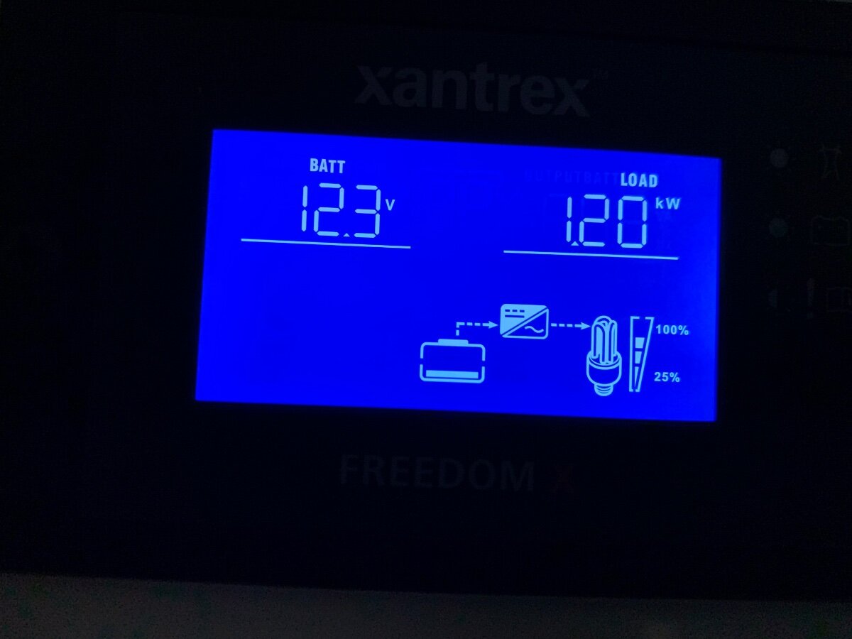
When running the A/C on inverter, I’ve really learned to watch the battery voltage displayed on the Xantrex wall-mounted remote, much lower than the reading displayed via the VictronConnect app for the SmartShunt when under heavy load. Taken yesterday after running A/C for an hour. Looking forward to replacing the Dometic as @jd1923 advocates!
A/C running on inverter.
A/C turned Off.
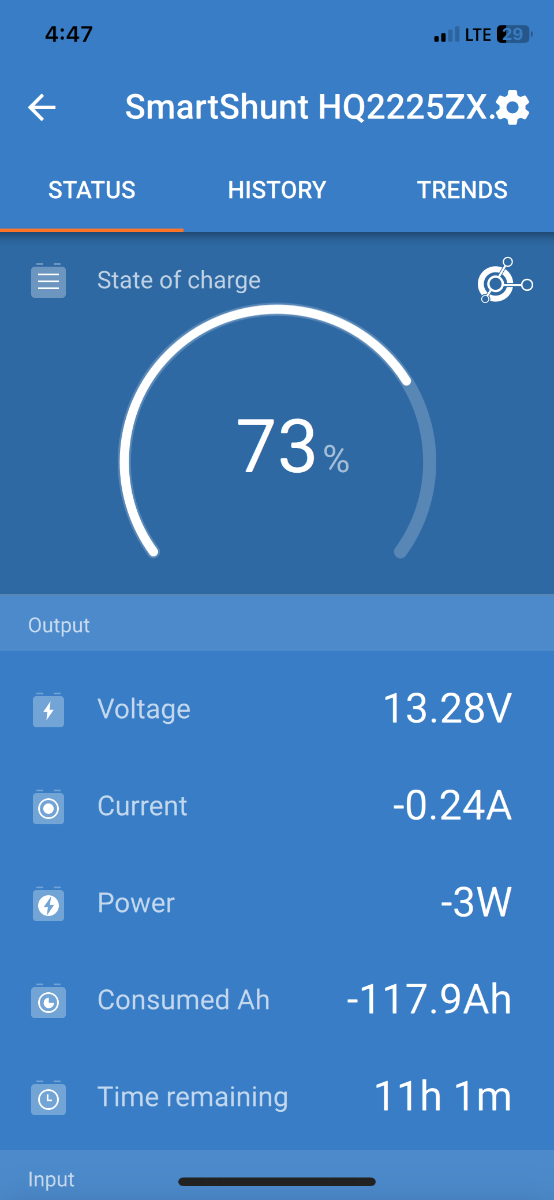
I’m beginning to think there is something wrong with this picture! Specifically, the divide between the Xantrex remote panel’s 12.3V reading and the VictronConnect SmartShunt reading of 12.86V; both taken within seconds of each other while under load running the A/C via inverter. I’ve recently had issue with system shutdown when the Xantrex threshold of 12.1V (recommended setting for Xantrex #02, LBCO Voltage, per Oliver for LFPs), even though my SOC was in the low 70s percentile. I have successfully been able to run the A/C up to two hours in duration without issue, but something seems to have changed. Upon searching the forum, I found where another owner reported a 0.5V differential and community consensus indicated that was NOT a good thing! As I recall, action taken was a hard reboot of the inverter involving total isolation by disconnecting the 12V cables for 3 days, which was reported to rectify said discrepancy. As of yesterday, a total reboot was instigated in hope of resolve. Your thoughts regarding this matter would be greatly appreciated, thanks!
-
On 6/1/2024 at 7:58 AM, Ronbrink said:
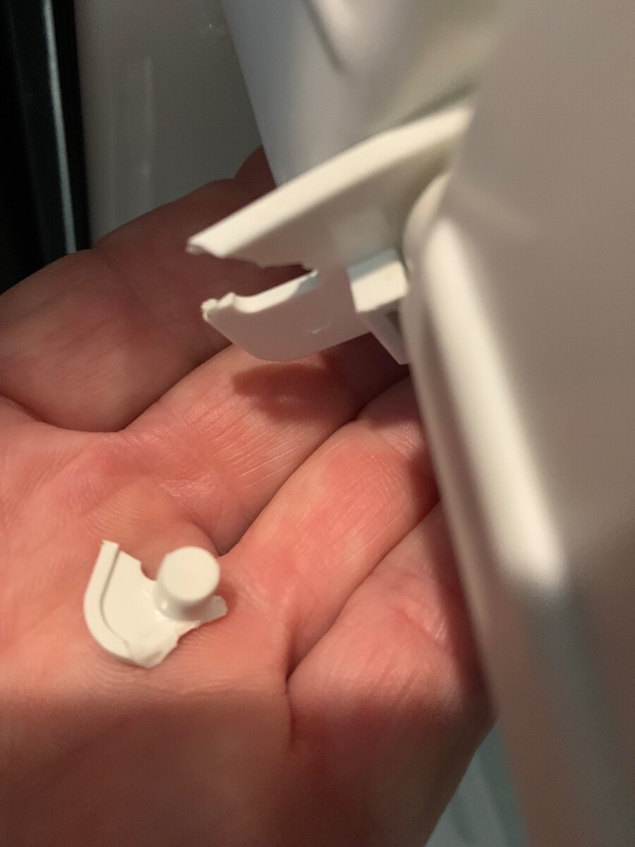
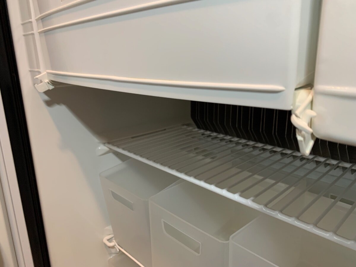
Had a similar hinge break on my Norcold three-way. Thinking a fix with Super Glue or similar product.
Well, before I had a chance to attempt a fix of the broken hinge, the other side broke shortly into a week’s trip. I did take a quick look prior to departure, but determined glue would likely not hold and besides, I misplaced the tiny spring. There was no urgency when heading out, since the single functional hinge had enough spring action to hold the freezer door closed. However, once it broke I had a troublesome floppy door to contend with. No bueno! Thankfully, I carry some Velcro strips and was able to rectify the problem temporarily. In fact now that I know the replacement hinges are fairly pricey, I may extend use of this fix for awhile longer.
Double trouble:
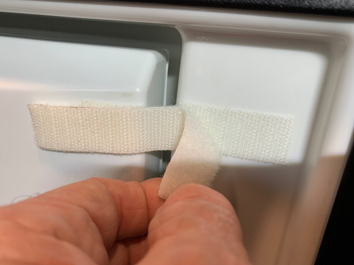
Short ‘hook’ section on each side of right door end:
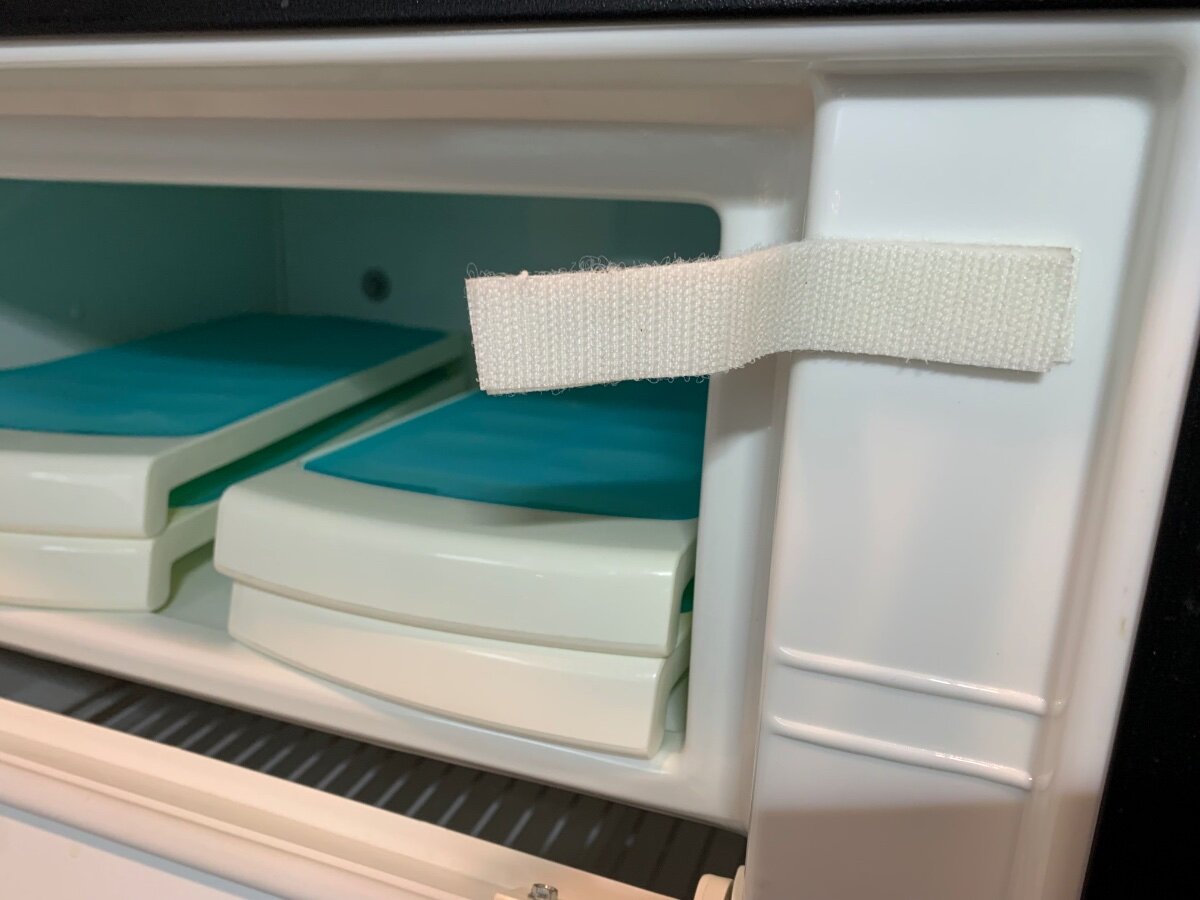
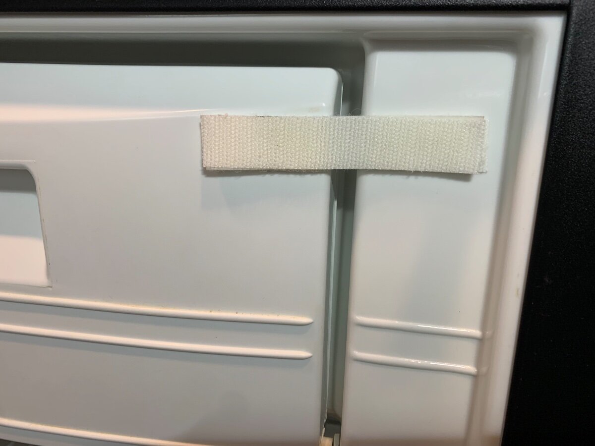
Back-to-back ‘hook’ and ‘loop’ strap for the door closure:
Mas bueno!
-
3
-
-
15 hours ago, Dave and Kimberly said:
Ron... how exactly do you turn the "inverter" off ? You mention two locations, one of which is the wall mount. Thats the only place I've ever turned it on/off. Where is the second place?
There is also a control panel with an On/Off button on the face of my Xantrex 2000. The wall-mounted remote is used to control power to the unit and the one on the Xantrex is kept in the Off position.

-
4
-
-
I would be hesitant to machine wash and a dryer may cause them to shrink. I suggest you try an automotive fabric upholstery cleaning product or one of those steam cleaners with an upholstery attachment.
-
3
-
-
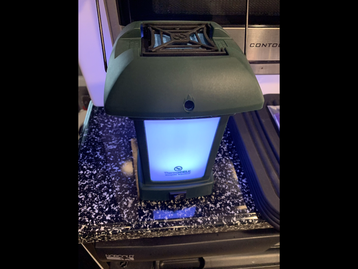
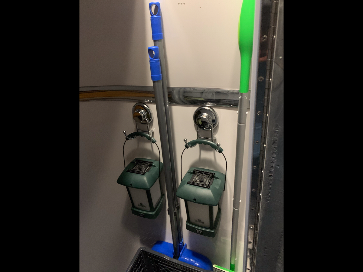
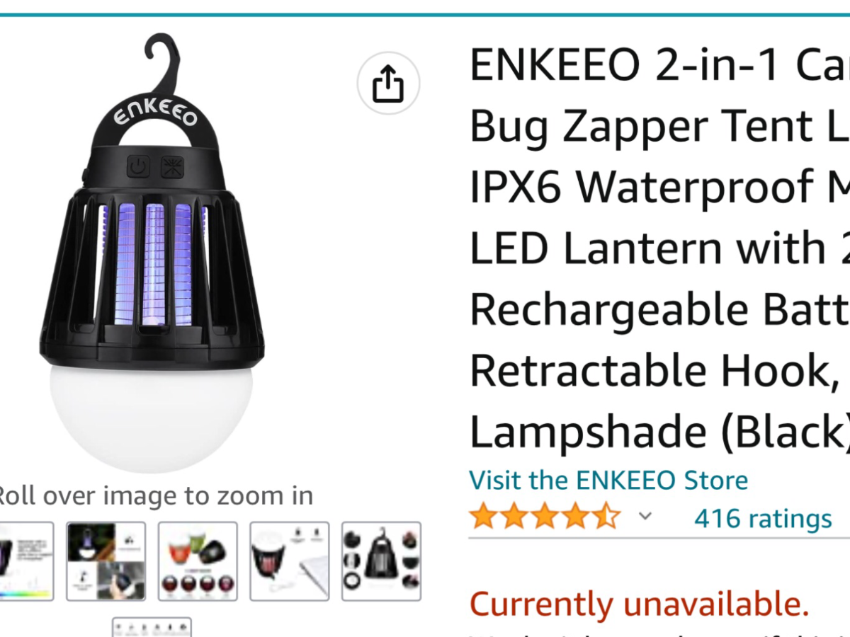
We’re in Clear Lake near Galveston, I ‘m a mosquito magnet! We carry Thermacells, one handheld and three latern style. The handheld is kept near me and the laterns are positioned around the immediate camp. I have a dropper bottle containing Pyrethrin to recharge the scent pads, very cost efficient and very effective! I really don’t like to spray down with harsh insect repellant, but find the Repel Lemon Eucalyptus (Deet-Free) product pleasent for skin and clothing applications and effective. Inside the Oliver I hang a couple of bug zappers for the occasional pesty invaders. If anywhere for a length of time, the screened Clam is deployed. Although I don’t like using, sometimes there’s a need to sweep camp with Cutter Backyard Bug Control.
-
2
-
5
-
-
On 6/4/2024 at 8:48 AM, Ronbrink said:
I would have to make a weekly trip to the storage facility to activate the ‘initial’ charging aspect of the Xantrex to bring my battery bank up; this involved tripping the 30A main breaker Off then On again. Upon researching, I learned that the Xantrex has a 1A draw even when turned Off.
I would like to make a correction to my above statement; an inverter will draw 1A if left On with no load and zero draw when Off.
On 6/4/2024 at 11:26 AM, jd1923 said:I'm getting only -0.25A with the Xantrex 2000 OFF and breaker ON
I recently realized I did not have my inverter in the Off position at both the Xantrex and wall-mounted remote. The VictronConnect app now shows -0.24A Current, which is in line with your results.
-
2
-
-
11 hours ago, SeaDawg said:
Odo- ban. Our dollar tree has a little tiny bottle. A little goes a Ling way.
Great recommendation to @NHBoomers! I second the OdoBan, has a pleasant smell and more importantly, it works to eliminate bad odors. Been using for years in my skiff to rid fish and bait smells, and coastal grunge! Buy it by the gallon at Sam’s, sometimes sold with a ‘bonus’ spray bottle.
-
2
-
-
@jd1923 My power draw is <1400W, perhaps the difference being in the 11,000 vs 13,500 BTU units. I too had my Xantrex 2000 shut down once when the batteries, under load, dropped near 12V; a ‘red’ triangle was displayed on the remote panel, yikes! I never really paid attention to the display voltage reading until that happened, just relied on the SOC per the VictronConnect app; lesson learned! I’m still thinking the Atmos 4.4 will be a satisfactory replacement unit. I know of two owners that have planned installs, awaiting their initial impressions.
-
1
-
2
-
-
On 6/25/2024 at 10:03 AM, mountainoliver said:
Concerning the issue of running the Dometic air conditioner on battery power through the 2,000 watt inverter. I realized that I stated that the inverter could handle 2,000 watts load. (I have gone back to my original post and corrected it) Actually the inverter is very similar to a 2,000 watt generator. The Zantrex inverter will run 1,800 watt loads continuously and 3,000 watts surge not 2,000 watts continuously. The Dometic air conditioner draws about 1,600-1,700 watts. The inverter will be at it’s limits so absolutely no other AC loads while running the air conditioner!
When running the A/C on inverter, I’ve really learned to watch the battery voltage displayed on the Xantrex wall-mounted remote, much lower than the reading displayed via the VictronConnect app for the SmartShunt when under heavy load. Taken yesterday after running A/C for an hour. Looking forward to replacing the Dometic as @jd1923 advocates!
A/C running on inverter.
A/C turned Off.
-
3
-
-
58 minutes ago, Steve Morris said:
So we ordered our trailer with the standard mattresses, and ordered KTT mattresses (the prior upgrade option) directly from the manufacturer.
We did the same with our 2020 twins, very satisfied with the high quality and firmness of these latex mattresses. Since on the subject, can anyone recommend a quality cover/encasement that is waterproof and conforms to the curve of the Oliver?
-
There is a new video on the Sprinter-Forum highlighting the Atmos 4.4 in a ‘non-ducted’ installation on a 2020 mini motorhome (make and model escape me). Unlike other videos posted in that forum, this one mimics more closely the perceived install in an Oliver IMO.
-
2
-


Victron MP2 with (2) Epoch 460ah batteries. DAY #1 Removal, rewiring, mounts, routing wires
in Ollie Modifications
Posted