Snackchaser
-
Posts
281 -
Joined
-
Last visited
-
Days Won
19
Everything posted by Snackchaser
-
A different refrigerator fan option
Snackchaser replied to Snackchaser's topic in Ollie Modifications
It's literally just dangling in place between the fins on the right side of center, near the top. The fit is tight enough and it works well. You could bend a little "U" clip to hold it in place if wanted. Some areas on the right side near the gas burner get really hot when the flame is on, then it cools quickly. The condenser fins near center represent a more average temperature. We used to set the temperature control to max cold in hot weather to keep food from spoiling. My wife is happy that she doesn't need to constantly adjust the temperature anymore. -
Adding Water Accumulator to pre 2018 Elite II
Snackchaser replied to bradbev's topic in Ollie Modifications
That was just a model number listing error. Here is some advice from a Shurflo tech for setting charging pressure, from a thread titled: "Are two accumulators better than one?" -
There is some info here:
- 1 reply
-
- 2
-

-

-
RVLock company stands behind its product
Snackchaser replied to Snackchaser's topic in Mechanical & Technical Tips
Great story! It's exactly why I'm a big RVlock fanboy! They are an underrated convenience. I can't count all the extra steps we've saved from having to fetch the elusive keys! I'm totally fine with my failures, I blame it on living in the great northwet rainforrest, where it even rains in my garage. I respect how they've used the failures to refine a more reliable and better quality product. The last free upgrade they sent looks well sealed, should last a long time! Their outstanding customer response is reason enough for me to be faithful to the brand! Besides, they're great looking too! They compliment the Olivers modern hi- tech look, and the neighbors are always impressed! Love the sound effects! -
You said the jacks work. Jacks are fed from load side of the DC panel 60 amp breaker, so it's fine. The DC fuse panel then feeds a number of things such as the stereo, pump, furnace, refer, ect., and the main switch panel. You mentioned the lights don't work, but the awning and camera do. I have not verified this, but it would make sense that the master switch on the main switch panel only controls the lights including the outside, inside, and closet. That's to avoid battery drain if you left a light on. You wouldn't want the camera or awning to be turned off by the master switch, so it's the primary suspect. My master switch failed and I had to jiggle and flick it a few times to get the lights on. Turned out to be a loose spade connector on the back of the switch. Best to pop the switch out and check it now to avoid an unwanted black out. Hope that solves the problem. Geoff
-
There are two types of generator transfer switches, ones that break the hot wire only, and ones that break both hot and neutral. If a hot wire only switch is used, then the generator must have a floating neutral or there will be dual bond condition as @CRM mentioned. Conversely, a double pole switch needs a bonded generator or the bond is lost. This is why some generators come with a bonded or not option. It’s difficult to explain why neutral-to-ground bonding works, but I try in the simplest terms with plausible scenarios. If a hot or neutral wire becomes shorted to a conducting element of the trailer, such as the skin or frame, then a person touching the frame could create a current path to earth and get shocked. However, the ground wire is bonded to the trailer frame — so with a normal properly bonded power supply, a fault to the frame would result in a direct short that would trip the breaker. If using a power pack such as the Bluetti, then there is no path to earth and such a fault would energize the frame. There is no current path to trip the breaker. You could touch the frame and create a shocking path to earth. This is where a bonding plug comes into play. With it installed, a hot-to-frame fault becomes a direct short back to the source's neutral — this collapses the frame's voltage to near zero and may trip the breaker outright. Either way, the frame is no longer dangerous to touch. I hope this helps explain a very complex, but interesting, subject! Cheers! Geoff
-
That’s a great comment. In reality, the manufactures are producing these things faster than the regulatory bodies can keep up. Merely disclosing a floating neutral is enough to keep them off the hook for now at least. This was first mandated for the generator industry, and It’s ultimately the installers responsibility for how they are connected and used. These power packs have a least off-set the risks with built-in GFCI’s for personal shock protection, but that does not satisfy the long standing rules for bonding that the trailer industry must follow. This is directly related to the trailer “hot-skin” issue that was bandied around for years. They recently codified long overdue requirements for trailer Ground Monitor Interrupters (GMI) that will be phased in over the next few years. Similar to the EMS (except it can’t be by-passed), the GMI’s will prevent the use of non-bonded power supplies, and it will be non-optional for new trailers. We watch with interest how this story fully evolves! Cheers! Geoff
-
The bonding plug needs to be at the source -- the Bluetti or generator outlets. Not an outlet in the trailer. Because the Bluetti outlet has nothing connected to the ground, the bonding plug cannot join the ground and neutral. Therefor a one-to-three outlet adapter can be plugged into the Bluetti, one of the three adapter outlets gets the bonding plug, another gets the trailer feed cord, and the third is a spare. That effectively bonds the ground and neutral. Bonding at the power source has always been required by code, these power packs just add a new dynamic. Someone had an idea to use the EMS bypass "in a pinch." This isn't risk free, but it would be fine for getting the lights on while finding the bonding plug. The EMS is actually protecting the trailer from an un-bonded neutral that the bonding plug fixes. Keep in mind that these power supplies are perfectly fine for single power cord loads as designed. They are not designed to be connected to a trailer where the wiring system assumes a bonded supply. Cheers! Geoff
-
I've never heard of a Blueitti. However there are a similar issues with a Jackery. They have what's called a floating neutral. Also common in some generators. So yes, a floating neutral requires a neutral to ground bonding plug. Otherwise the Electrical Management System (EMS) will see it as an open ground. But there is a problem. Many (if not all) of these power packs have no reference to ground what-so-ever. So the "u-ground" pin hole of the receptacle is not connected to anything, it's just an open hole. So a neutral to ground bonding plug wouldn't connect to anything in the ground pin hole, and it won't work. Now that I've confused everyone, including myself, there is a bypass trick. Use a 1-outlet to 3-outlet adapter, or an extension cord with a "Wye" that provides 3 extra outlets to plug into. Plug the neutral to ground bonding plug into one the extra outlets to effectively bond the neutral and ground... despite there being no ground on the power pack. Cool huh. This is one of many reasons to have a $10 plug-in circuit tester, the ones with three lights that show various conditions such as open grounds. I recommend you test all circuits when rigging such power supplies. Cheers! Geoff
-
We met Oliver owner “Rob” from Florida at Manzanita Lake in California! Not many Olivers in these parts and it was a thrill to meet you! I was sorry we didn’t get a chance to chat with the wives together. Our camping group was demanding, and then you were gone. I didn’t find your profile on the forum, so here’s a public shout-out, and I hope your trip was great! Cheers! Geoff and Tanya
-
Jd, thanks for the complimentary words as always! I mentioned the Auto Electric Specialist option because many folks may not know it’s a thing. It’s an ASE recognized field and most areas have them. We actually have three exclusive Auto Electric businesses here in small town Eureka. I also remember at least a couple of them when I lived in the Phoenix area near you. I don’t rule out that the truck has a problem, but I believe it’s the trailer because the dealer cleared the truck, and there were no other trouble codes. Wiring issues were found in the trailer and the repairs made the issue go away temporarily, so odds are that’s the source. Electrical problems can be very elusive, and often beyond DYI electric testing skills. My mention of a possible brake controller problem, or PWM digital interfaces, was merely meant to show that the problem could be almost anywhere, and one must consider that in their repair decisions. After several mechanics failed to find the problem, it’s reasonable to assume it’s not a simple problem to find. That’s why it would be “lucky” to find it with simple tests. My suggested test might find a ground problem, which would explain both the brakes and the flickering lights. However, intermittent problems, high resistance connections and shorts, degraded brake controllers, etc., could all cause similar symptoms, and they can be very hard to find. You'r right about the black wire, I must of had a brain embolism on that one. And I should clarify that the junction box is a likely place for problems to occur, but I’d probably start testing from the main ground bus under the dinette, and work backwards to the truck — only if there was high resistance or an open… keeping in mind that the brake circuit probably branches out separately from the junction box which further complicates testing. Also I didn’t mean to shut-down your emergency brake breakaway switch amperage test idea. However, it’s fed directly from the battery and a completely separate circuit from the TV. In fact, your low amperage readings didn’t compute with expected amperage for 4 brakes, so perhaps the switch only controls the brakes for one axle. Regardless, it’s doubtful that a problem in that circuit would show-up as a TV brake issue. Also, the hot side of the TV brake wire could create similar symptoms if there was a short to ground. That could be even more tricky to find. Some might use a Megger to test the wire insulation… which is over kill for 12v circuits. A jiggle test with a multimeter is the way to go, but it’s hit and miss. Anyway, see how quickly it gets complicated. I don’t like to throw out too much detailed information to confuse people, but I re-iterate that there’s more to it than folks might realize, and that’s why there are so many auto electric specialist’s. Hope that clarifies things! Cheers! Geoff
-
True Induction Stove Top will not turn on
Snackchaser replied to Lamar's topic in Mechanical & Technical Tips
Although you certainly could run the stove from the 2000w inverter, you would have to accept some compromises and operational limits on how you manage your power: You obviously can’t run the stove and microwave at the same time, but just running the stove at full power is pushing the 2000w inverter close to its limits. Adding another small plug-in appliance, hair dryer, coffee pot, toaster, would likely trip the inverter. Inverter trips are a design function, but it creates wear and tear, and manufactures strive to avoid this kind of customer inconveniences and distress. A 2000w inverter charges 50% less than a 3000w (100a/150a). This it to make up for the higher power consumption of high wattage appliances. These are reasons enough why Oliver didn’t connect the induction stove to the 2000w inverter. The 3000w inverter has 50% more capacity and you wouldn’t have the same restrictions. Oliver’s real mistake was overlooking the boondocking aspect. Bottom line; I would never accept a solution to connect the induction stove to the 2000w inverter, I doubt a new trailer would ever leave the factory that way. In my opinion, they should upgrade the inverter and wiring to 3000w to give you what you contracted for. A propane stove would be second choice because why should you settle for less than originally promised? I wish you the best in your negotiations, and I hope that Oliver will try to make it right. Cheers, Geoff -
I don’t want to offend anyone, but I have an entirely different view on this issue. It might be time to pull in the reins on the piece-meal fixes and take a fresh look. At lot of the advice provided is based on conventional auto electrics and trailer wiring. But things are much different with today's vehicles. There is changing technology with Pulse Width Modulation (PWM) switching, and the way it interfaces with modern LED lighting, and the low-to-ground switching of your Chevy that requires solid grounding. High resistance grounds and shorts can be hard to locate, and they can cause ultra low currents that will be detected by digital systems of new vehicles. These include grounds and shorts that might only appear under heavy loads, such as from your brakes. The heavy loads can cause insulation breakdown and arcing that might not be otherwise detected. The flickering lights you mentioned might be an artifact of your 2023 truck’s older PWM system and a separate issue, or it could be caused from a poor ground. It could also be caused from a failing brake controller for example. I agree that it’s most likely a trailer wiring issue, but I wouldn’t go rewiring the 7-pin or axle wiring just yet, or renting a u-haul with a 4-pin adapter because you will not get definitive answers. Unfortunately, new grommets will not help at this point either, the wires were already taped. The breakaway switch amperage will be ambiguous too. A direct short would smoke the wire, a high resistance short would be lost within the range of 9-12 amps for the 4 brake coils. But there are enough clues to point to a potential ground issue, so a ground check would a good start for most DIY folks. The trailer is grounded to the TV in 2-ways. Through the hitch ball, and via the 7-pin ground wire. The ball ground can be iffy, so the wire ground is important! You can see the black ground wires in your junction box picture, they are connected to studs that are grounded to the trailer chassis. A good place to start checking. Use a multimeter on ohm’s setting. Find a good ground on the TV for grounding one of the meter leads, and then start checking ground points on the trailer with the other lead while jiggling wires, including those on the axle. You will need two people, and maybe jumper cables to extend the test lead length. You should have fairly consistent low ohms readings. You might get lucky and find a loose connection. However, it sounds like various technicians have already checked for obvious problems, so at this point you are really in the territory of an Auto Electric specialist with proper logging instruments to test for intermittent problems and the ability to accurately trace circuit continuity. Auto electrics is a field of it’s own, and they are far more knowledgable that the dealers and regular mechanics. Just my two-cents. Good luck! Geoff
-
Main battery switching, a different approach
Snackchaser replied to Snackchaser's topic in Ollie Modifications
I heard that😁 But I'm no EE… just an uneducated and curious mind. The first priority in all my modifications — and frankly the cleverest aspect — was minimizing impact on the Oliver's stock functions and appearance. Most modifications can be removed without trace: no fiberglass damage, original functions intact. Everything is fully documented in a binder with detailed drawings any competent technician could follow. This should be a standard practice for every DIYer — and frankly, it's not something Oliver itself can boast based on all the speculation we see in this forum. Cheers! -
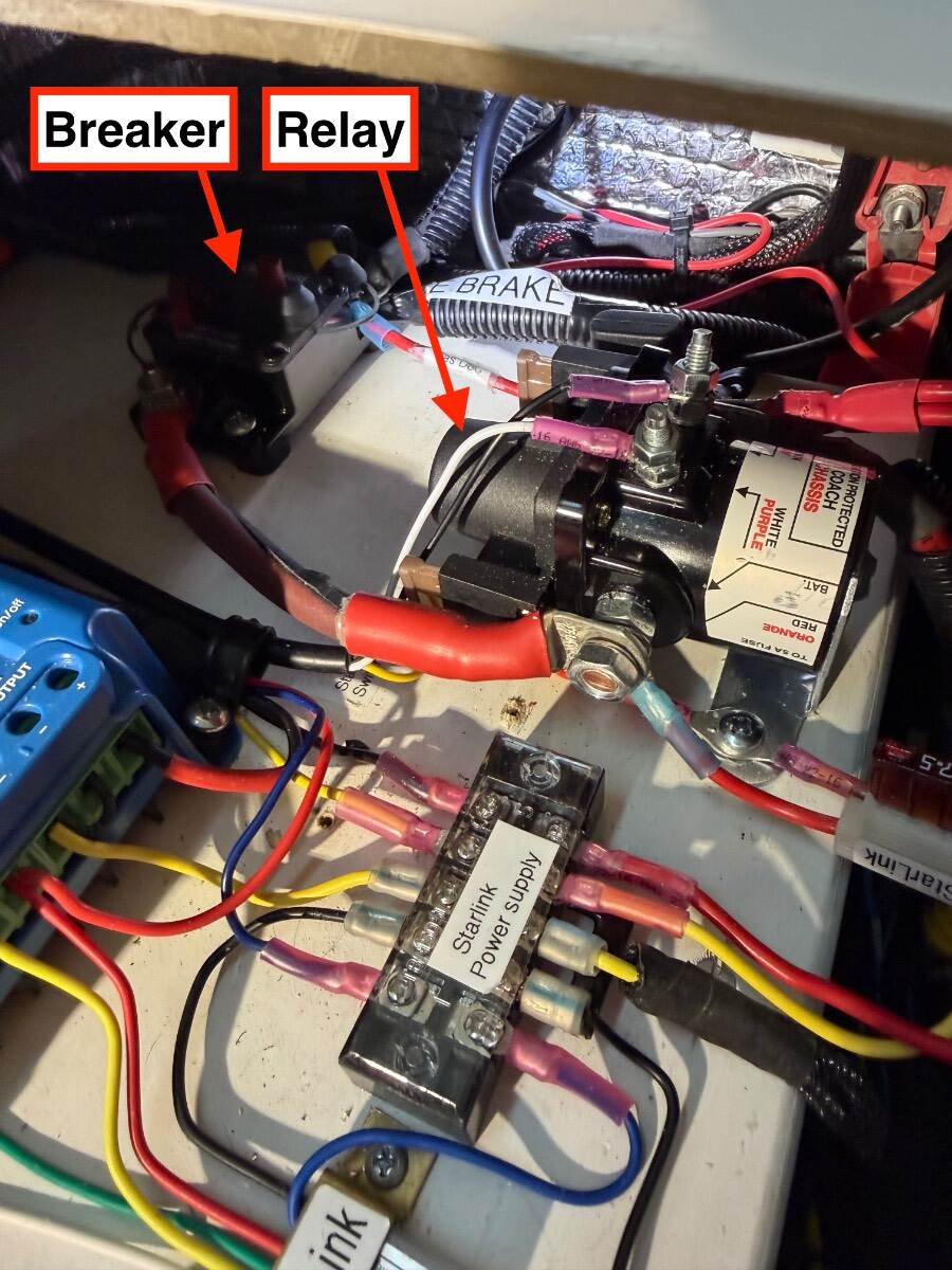
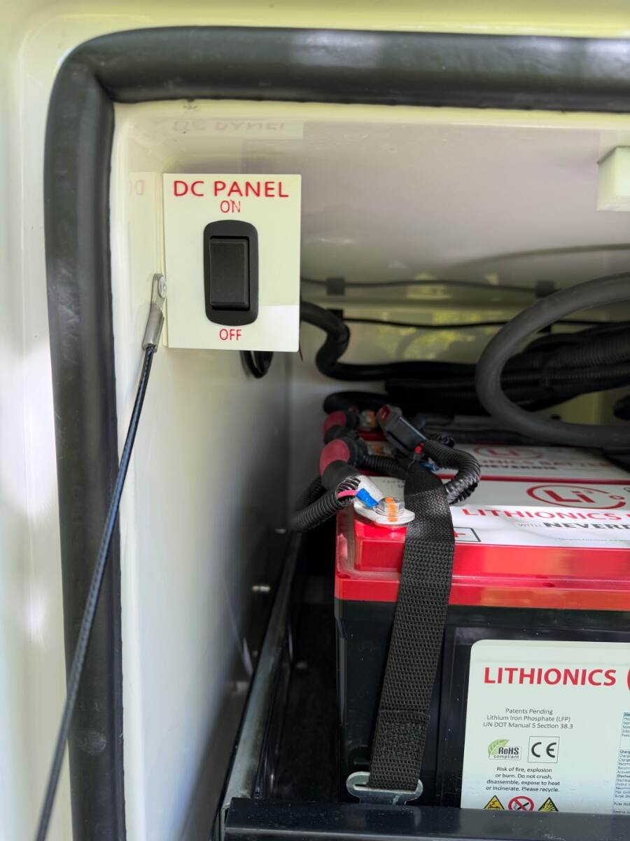
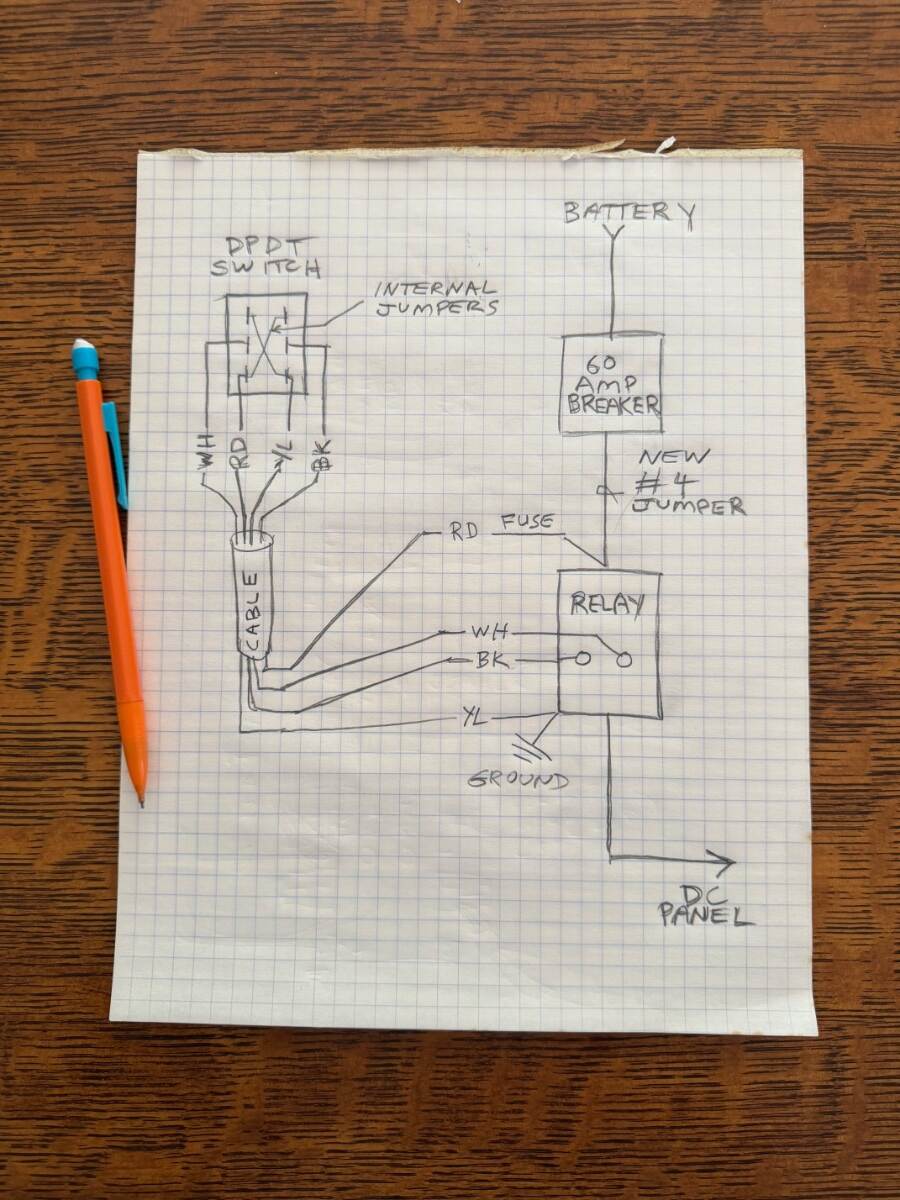
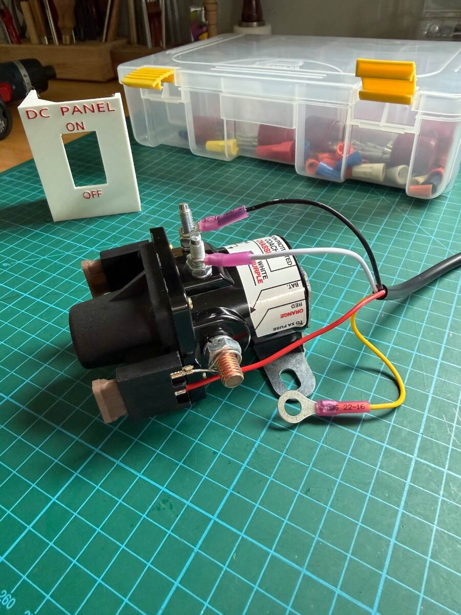
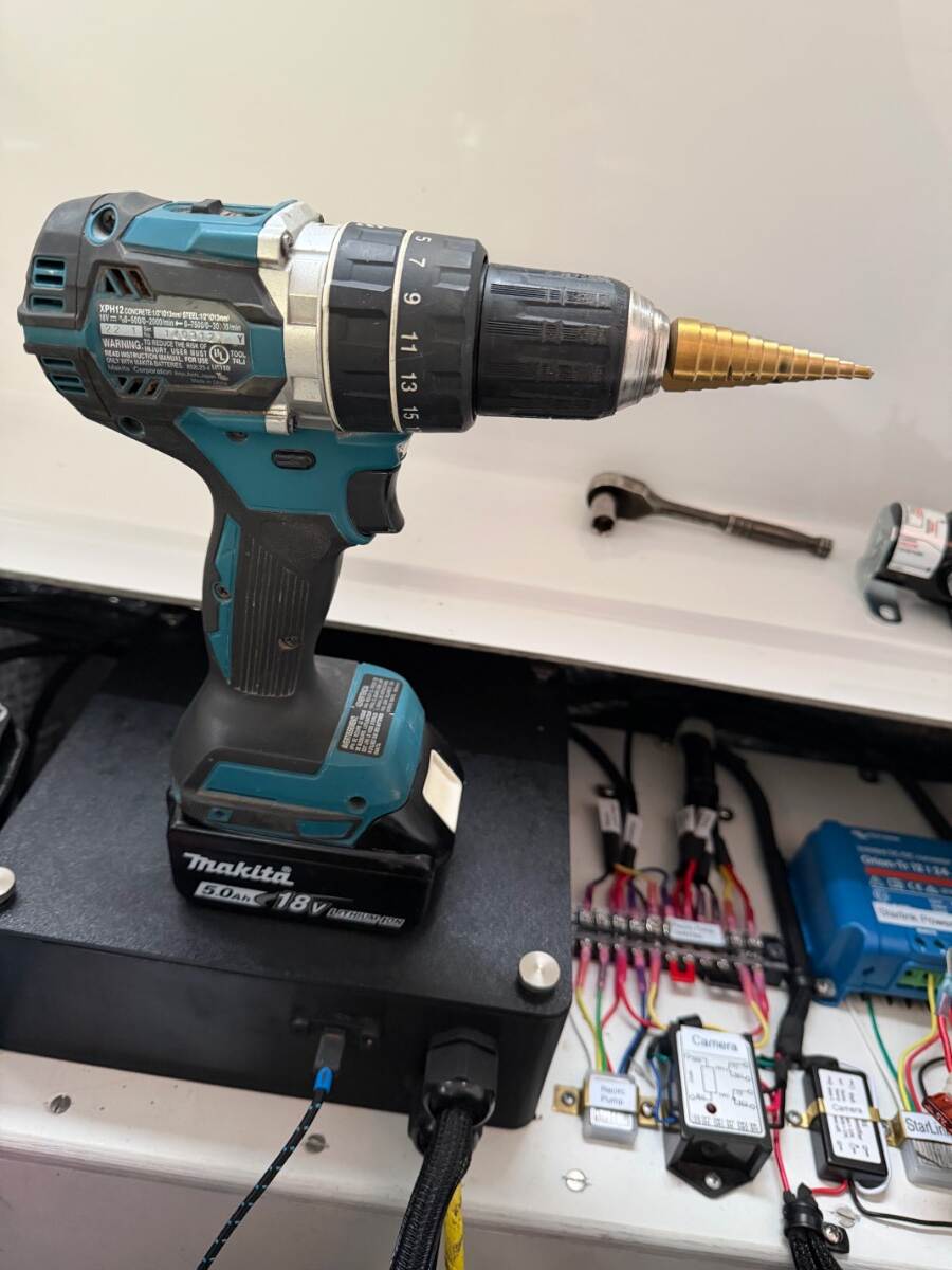
There are many great postings for installing a main battery switch. Folks like them for safety reasons, to kill parasite loads during storage, or for when working on the system. But I’m not a big fan because the safety benefits are more mythical than real, and 96% of parasite loads can be killed by shutting off the 60 amp DC panel breaker. I just don’t like introducing unnecessary resistance in the high current battery circuit. In rare cases when the main battery circuit needs to worked on, the battery can be disconnected, or the 300 amp breaker can be opened. Even with liability exposure, Oliver’s decision not to have a main battery switch was a deliberate and sound engineering choice in my opinion There may be some merit-worthy arguments for one, or perhaps a lingering perception that one is needed because it’s a requirement in the marine industry for different risks. In reality, the need to cut power in 12-volt RV systems during emergencies is rare and not normal practice. Besides, most firefighters are trained to cut battery cables before looking for a switch, or trusting it. There is no shock hazard from the battery, and breakers and fuses are more reliable protection against fire hazards, than relying on the right person being in the right place at the right time to find a switch. I've seen a number of battery switch installations that completely disconnect the battery. This can actually create more credible safety hazards than it prevents. A towed trailer with its battery switched off has no emergency breakaway brakes and no gas or CO detection, both of which should never be switched off. The solar and AC chargers are also disabled in that configuration. However, switching off parasite loads is definitely a good idea for storage, but it doesn’t require switching off the entire battery. In the example shown below, the DC panel carries 96% of the parasite load. The remaining 4% of parasitic load comes from the inverter/charger, solar charger, and LP/CO alarm which are all connected directly to the battery. I don't believe it's necessary or advisable to disconnect these circuits for normal off-season storage because those parasite loads are non-consequential. For unusually long storage periods, some additional battery maintenance would be needed regardless. The parasite load percentages below are based on precise measurements of my Oliver trailer with a 390 amp battery, your setup and amperage may vary. They include electronic standby currents from various LEDs, memories, displays, power supplies, and such. There is no singular large load, but they collectively add up: Circuit Draw DC Panel load 0.48 A 96% Inverter, Solar Charger, Gas/CO detector 0.02 A 4% Total measured from battery 0.50 A 100% DC panel breakdown: Fuse Circuit Draw 2 Various electronics 0.117 A 4 Furnace 0.012 A 5 Main lighting 0.003 A 6 Fans 0.016 A 7 Truma water heater 0.113 A 8 *Furrion Radio 0.204 A 9 USB outlets 0.007 A 10 USB outlets 0.009 A Total 0.481 A *My new IRV stereo is only 0.083 A Under ideal conditions, a 0.481-amp load from the DC panel would deplete a 390 amp-hour battery in roughly 34 days. Real-world depletion will be faster due to BMS overhead and temperature effects. The remaining 0.02-amp load from the non-DC Panel circuits would take approximately 2.2 years to deplete the battery. A lead acid battery system without inverter would have less parasite draw with the DC panel shut off. It would still last a 7 month storage season before depleting the batteries to a safe 50% discharge. I used to turn off the DC panel with its 60 amp breaker under the street-side bed. Although effective, it’s inconvenient to reach. This modification provides a more convenient way to turn it off with a latching solenoid relay controlled by a small switch. Latching means it holds position without any power draw, it only consumes current for the instant it switches, adding nothing to the parasite load. These relays are designed for exactly this purpose and are commonly used in boats and RVs. I used an Intellitech style RV latching relay rated for 100 amps. The relay mounts next to the 60-amp breaker. The existing DC panel feed wire is moved from the breaker output — to the relay output. A new #4 AWG jumper goes from the vacated breaker output — to the latching relay input. Premade made jumpers with ring terminals are readily available in 6” & 12” lengths. Note: The 60 amp breaker may also have other loads such as the electric jacks. The jacks do not have parasite loads, but turning them off is a form of anti-theft protection to prevent the trailer from being towed away with jacks deployed. If you choose to move these loads to the relay, then the ring terminals need to be enlarged from 1/4” to 5/16” stud size to fit the relay. Use a sheet metal step drill to enlarge the terminal ring lugs while holding them with pliers, otherwise a twist drill will grab and destroy it. Step drills are great for drilling chip free holes in fiberglass tool. The relay is controlled with a Double Pole Double Throw (DPDT) momentary switch with a spring return to center. This is the same type of polarity-swapping switch used for the electric jacks. The switch can be located in any accessible and convenient location. I put mine in the battery compartment and wired it with a jacketed 4-conductor 18-gauge cable. The cable fits snugly through a 5/16” hole drilled next to where the DC panel wire penetrates the battery compartment. I linked one option for a switch mounting bracket. However, I made my own 3-D printed bracket with a red label to identify it as the DC panel shutoff. The print STL file is available, or I have a few extras if anyone needs one. I mounted the switch bracket with high strength double-stick foam tape and stick-on zip-tie mounts for the wire. The DC panel can now be turned on/off with the switch, without disturbing the inverter/charger, solar charger, or safety circuits. Newer Olivers have a solar disconnect switch and it’s possible to use the latching relay to disconnect the solar too. However, there is limited space on the relay’s stud for circuits so a terminal block would be needed for that purpose. I couldn’t find decent wiring instructions for the relay, so I provided a sketch. The relay comes with two fuses, use the one connected to the V+ input to power the switch. The other fuse is for an optional switch indicator LED. The switch’s V+ wire connects directly to the fuse spade with a female spade terminal. BTW: As seen in the picture, my installation is way more congested than normal due to other modifications. I have a large piece of plywood for mounting all my gadgets, you may need to glue a small wood mounting block for the relay. Just trim the insulation and use a good construction glue or epoxy. Here are some Amazon links for parts: Latching 100 amp Relay https://a.co/d/09MjQYjx DPDT momentary return to center switch https://a.co/d/0hNXSZkO Switch bracket https://a.co/d/08qc1lvY 4-18 AWG cable https://a.co/d/05Zn0CF6 6” x #4 AWG Jumper https://a.co/d/049xhKq6 Zip tie mounts https://a.co/d/0iRWzLD2 3-piece step drill kit https://a.co/d/01TaDQmg Hope you find this useful. Cheers! Geoff

- 13 replies
-
- 10
-
-

-
-
Furrion Stereo Upgrade: A Sound Choice
Snackchaser replied to Snackchaser's topic in Ollie Modifications
@rideandfly Nice work! That's some clever engineering! -
It you look in the closet, there is a horizontal section of vent pipe about three feet long. If the trailer was parked with the nose up, that section of horizontal pipe would fill with water if the vent cap was off, or water was sprayed up under the cap. That's the only reasonable scenario that would cause blockage of the vent and result in slow drainage. Seems like dropping the nose back down would drain that standing water better than going on the roof with a vacuum. 😁 Us retired folks got to be carful on ladders! Cheers! Geoff
-
@dkeen, you're correct about using the tester. With the black probe on the ground bus, check for voltage with red probe on both sides of the fuse - with the fuse in place. There should be power on both sides of fuse. But that is probably not the problem if you already confirmed continuity through the fuse. If the fuse LED does not light with the switch on, it means that there is an open somewhere in the pump circuit. Probably a spade off one of the switches, or bad connection somewhere. Here are some easy checks: There should be a wire connected at the back of the panel directly behind the pump fuse. Count fuses from the top down to the pump fuse, and count same number of spade terminals from top down in the back — that will be the pump circuit and the easiest connection to check first. Just verify that the wire hasn’t pulled off the spade. Look at the pump wire connections next, pull on the wires to make sure they are properly spliced together. Least probable- You can slip your test probe into the pump butt-splices and check for volts to ground. Check all the pump wires with switch in both positions. !2 volts on any of these wires means you're getting voltage to the pump. If you have voltage, then the pressure switch is suspect. It should be normally closed. If it failed in the open position, then the pump and fuse indicator won’t work. If you haven’t found it at this point, then it gets more complicated and probably beyond typical DIY skills. The switches are 3-way, wired with the power going to one switch and the switch leg going to the other, with travelers in-between. The bath switch requires removal of the shelf which is a project on its own. This is further complicated by an in-line relay that handles full pump current so that the switches don’t have to. Sounds like your going to Oliver anyway, so its probably best to have them fix it. Even a seasoned RV repair guy would spend a good amount of time finding the problem. Good luck, Geoff
-
The pump fuse clearly has power because it's connected to the same bus as the other working fuses. That red LED blown fuse indicator will only light when there is a load on the circuit. If the circuit is open, say the pump switch is off, or the pump/switches became disconnected, then there is no load and the LED stays off. With the DC panel fuse pulled out, try the switching the pump on to see the LED lights. That will tell you if the is an open connection somewhere in the circuit. Remember the circuit includes both the hot wire and ground. It's most likely that an open connection would be at the pump, either one of the the switches, or possibly at the back of the DC panel where the pump circuit connects to the fuse. Least likely that it's a broken wire, bad pump, or open ground. I believe the pumps ground goes directly to the main ground bus, it does not go to the switches, although the switches will have ground potential through the pump motor windings. It's possible that the connections to the bathroom switch have come off, but it sounds like you might have checked that already. You're on the right track thinking it's an electrical problem because the green light does not work. However, I would recheck your valve lineup because it sounds like you're trying to draw water in through the boondocking connection. It is possible that the pump is pressurized and the pressure switch is open preventing the pump from running further. . Good luck and let s know what you find. Geoff
-
True Induction Stove Top will not turn on
Snackchaser replied to Lamar's topic in Mechanical & Technical Tips
In looking at the circuit description that @Steve and MA provided, it seems that there are two separate feeds. The 30 amp main feeds circuits 1 through 3 which include the water heater, AC and Inverter. These would appear to be circuits that run only on shore power. The water heater (20 amps) must be a propane/AC unit and it makes sense that this would not be energized from the inverter, likely not the AC either. Then there is the "SUB-MAIN INVERTER SUB-PANEL 25 AMP." You could infer that this 25 amp feeds loads that run from the inverter (circuit 4 receptacles and circuit 5 microwave). This is not the correct circuit description for your trailer because stove top load is not listed. However, it does provide clues for what could be going on in your trailer. If the inverter does not support the AC, then it probably doesn't support a high amp induction cooktop either. That would be crazy that a stove cannot be used while boondocking! There are some Xantrex models that have built in circuit breakers for split feeds like this. So there could be the AC sub panel under the dinette feeding AC inverter circuits, and shore power breakers built into the inverter for the water heater, and stove-top. Just an idea to look at, I hope that's not the case though. Geoff . -
True Induction Stove Top will not turn on
Snackchaser replied to Lamar's topic in Mechanical & Technical Tips
Lamar, sad to hear of your troubles! I have no idea how those stoves are wired, but they should be GFIC protected (Ground fault interrupter circuit). Those can trip for numbers of reasons. It could have its own GFIC receptacle under the cabinet somewhere, or it could be fed from an another GFIC receptacle. I'd check all the AC receptacles to see if they are GFIC and if they are tripped. Don't forget the one above the kitchen counter and the outdoor plug. If you find one tripped that won't reset, let us know for further investigation. Also check the AC wiring diagram in your manual, it should show whether the stove circuit is GFIC protected, and give clues where to look. The stove wouldn't be related to the 12v outlets. If you're talking about the USB outlets, they might have a tiny pushbutton switch on the front of them. The cigarette lighter type of 12v outlets are notorious for having the wire terminal pop off the back, but unlikely for that to happen to both of them. If the fuse is okay, then I'd take a close look at whatever you're testing them with. Good luck and let us know what you find. Geoff -
Good idea! You could, but isolate it from the TV so you don't end up with a back-feed condition. Just use a DPDT switch wired to break the TV circuit while energizing the back-up lights from the trailer battery, and vice-versa. Geoff
-
Jd, good modification! Our friends had their bikes stolen off the back rack and they heard it happening. They wished there was a rear light to scare them off. I was just thinking, it would also be real easy to add a 3-way rocker switch under the attic cabinet that could be reached from bed! I remember when looking for the street-side light switch leg that I also found the overhead lights wire. So I'd just keep looking, it should be there and perhaps a different color. Also, the switch leg is on the positive side. Anxious to hear how it goes! Geoff
-
Disclaimer - I have zero knowledge of these units, I 'm just going on basic trouble shooting methods. If you did a factory reset on the CP, then it probably needs to be re-paired with the devices (furnace, Water Heater, and AC ... assuming that the AC is also a Truma). Start by going into the CP setup/pairing mode to see what devices are connected and/or available for pairing. It could be that the furnace was never paired during initial setup. The manual should have instructions for this. If the Furnace is not listed, then check the furnace fuse because it needs to have power to talk to the CP. Next check the LIN cable as @Galway Girl showed in the video, only it's the one for the furnace not the water heater because you said the water heater was working fine. Look closely at the pins on the LIN cable, they could be bent and not making proper connection. If the furnace end is fine, then check the CP end. Last but least likely, the furnace board might have issues. This is a good start, but there could be other problems to. Hopefully someone with more familiarity will chime in. Good luck and let us know what you find
-
Furrion Stereo Upgrade: A Sound Choice
Snackchaser replied to Snackchaser's topic in Ollie Modifications
I design stuff with a simple and free on-line program called Tinkercad, you can export designs as an STL file that is 3-D printer ready. A simple bezel design would take a few minutes. I started off using Voice-to-CAD, and AI generated designs, until I figured out how much easier Tinkercad is. I just watched a few tutorial videos on Youtube and the printer is pretty much plug and play. Honestly, I'm still re-wiring my brain to think of 3-D printing first, it opens up project possibilities that couldn't be done before. There are literally thousands of free ready to print designs for all sorts of things, including some great gadgets and parts you won’t find anywhere else. Check out websites like Thingaverse. Some designs, such as boxes, can be adjusted to any size, they have working hinges, latches, and sealing gaskets. A myriad of materials are available, including ABS, Nylon, and TPU, a rubber like material for flexible parts like gaskets. That “sealed” the deal for me. For mounting a new stereo in your larger hole, you could use JB weld to glue a couple of overlapping wood cleats on the backside of the hole for the mounting screws. Then make a bezel like Bill’s to fit. Geoff