Snackchaser
-
Posts
267 -
Joined
-
Last visited
-
Days Won
19
Everything posted by Snackchaser
-
Inverter freedoms 2000 is not turning on
Snackchaser replied to Skipster's topic in Welcome to the Oliver Forums
It’s unfortunate that your Xantrex died, and it sounds like the installer charged you full price for the unit, which is normal practice. But you saved a lot more on the installation cost by replacing it with another Xantrex because they didn't have to fit a different sized display or make wiring changes. Victron's are nice, especially if you have other Victron components all linked together. But I also like the Xantrex units, they are generally reliable and they have good lithium charging profiles, and they are very simple to set-up and use. FYI, be sure to check and re-torque your wire connections after using it. In last weeks YouTube episode of “Happily Ever Hanks,” their recently installed Victron Multiplus literally burned up! They don’t know why at this point, but in my opinion it was probably a loose connection. Cheers! Geoff
-
Although fiberglass is not conductive, the frame, bumpers and hitch are! It's possible for a trained person with the right equipment to check if the neutral is bonded at the pedestal. But there is no quick test plug-in device. It has long been the case that the neutral must be bonded to ground only at the main service. However, there are probably tens of millions of sub panels that are incorrectly grounded. But there are also many other improper wiring issues that are even more significant hazards. There is an old electrician's saying about apprentices, handyman's, and DIY'ers; "They know enough to be dangerous." Just be wary of armchair advice, it's what they don't know that will get you! Cheers! Geoff
-
Your friend is correct! The Oliver’s Progressive Industries Power Management System will shut-off power for an “open ground,” but it does not comply with the 2026 NEC changes that also requires monitoring for an “energized ground.” Either of these conditions can result in a “hot skin” shock hazard! Cheers! Geoff
-
Ollie in the Wild West! We were one of only a few travel trailers to ever camp at the historic Cerro Gordo Silver Mine and Ghost Town, which is 8,500 feet in the California Sierra Nevada Mountains. I took the Ollie up there while doing volunteer electrical work on a 150-year-old cabin that’s being turned into a recording studio. The road to Cerro Gordo is challenging and requires a high-clearance, sometimes even a 4-wheel drive. I had to use 4-low a few times to make it up the 8-mile access road with a significant elevation gain of 5,000-feet. The dirt road winds through narrow rocky canyons, switchbacks, steep shelves, and washboards. I was pleasantly surprised with the Oliver’s off-roading performance; the stock springs and shocks have over 30k miles and they worked perfectly to absorb the bumps and ruts without much bouncing or swaying! At its peak in the 1870s, Cerro Gordo had a population of around 5,000, and it was the largest producer of silver in the United States. It was like stepping back in time, and the views and sunsets were stunning. While the town is private property, it’s open daily from 9 a.m. to 5 p.m. for self-guided and sometimes guided tours. It is considered one of the best-preserved ghost towns with interesting buildings and equipment, including the mine, a museum, boarding houses, and even the original brothel. Unfortunately, the famous American Hotel burned down a few years ago, but it has been completely rebuilt and is close to reopening. The town is featured in the YouTube channel “Ghost Town Living,” and they have collaborated with other popular YouTube channels for mine exploration and various projects. Cerro Gordo is located near Lone Pine just off the famous U.S. Route 395, on the road to Death Valley. Cheers, Geoff
-
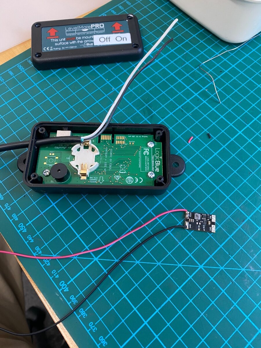
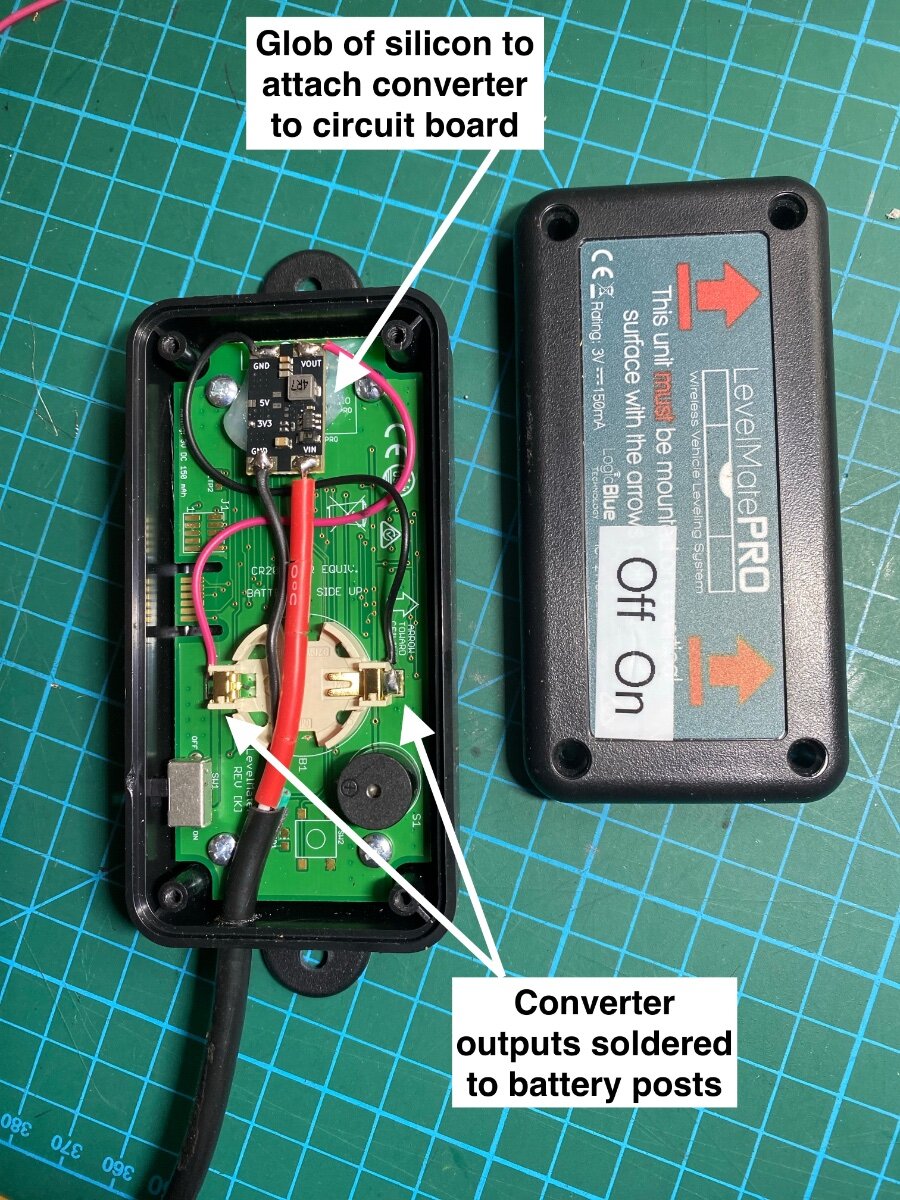
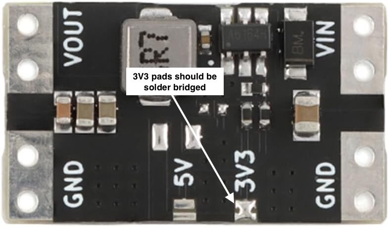
The LevelMate PRO is excellent for quickly leveling the trailer, and the battery is supposed to last six months. But I often forget to turn mine off and it always seems to be dead when I need it. In fact, it’s died so many times that I even kept extra batteries taped on the cover, quick release thumb knobs, and a screwdriver in my hook-up kit for changing the battery. Then on top of that, it has to be recalibrated for the slightest alignment changes when removed for battery replacement. I was fed up, and not willing to shell out another $150 for the USB powered LevelMate PRO+. So I spent $9 for a pack of ten voltage converters, and I hardwired the LevelMate to the trailer battery! The converters have an input voltage of up to 16VDC, and an output of 3.3vdc. They're small enough to mount inside the LevelMate case, the parasite drain is next to nothing, and the power switch will still remain operable. This is a simple modification requiring only basic electrical knowledge, some wire, a fuse, and a soldering iron! For the wire, I used an old charger cord. Hardware or auto parts stores will carry In-line fuses. Procedure: Open the LevelMate case and discard the battery Use a glob of silicon sealant to glue the converter on the LevelMate circuit board Drill appropriate sized hole for the power wire Verify the factory soldered a bridge across the Converters 3V3 pads to set output to 3.3vdc Solder jumper wire from converter GND to LevelMate battery pad marked “-” Solder jumper wire from converter VOUT to LevelMate battery pad marked “+” Solder Negative power wire to converter GND Solder Positive power wire to converter VIN Connect power wires to any negative and positive power source via a 2 amp fuse. My LevelMate is mounted in the garage space for optimum BlueTooth range close to the leveling switches. Power is available from the garage light, or you can pick it up from the “load side” of one of the breakers under the street side bed, or the dc power panel. Converter: https://a.co/d/7nvhv0A Note: This converter has a input of 4.5 to 16 vdc. Don’t be tempted by myriad of attractive looking 12vdc converters because they will not withstand the Oliver’s 14.5 vdc charging voltage. Now if I could only come up with ideas for the extra nine converters. . . Hope someone finds this useful! Cheers! Geoff
-
Sounds like a great feature on the truck! If I understand correctly, it has a separate alternator, etc. Well then, I'd dissmiss any efficiency losses because it's like the source generator, and we don't consider those efficiencies! In fact you may gain efficiency due to the higher voltage, and less voltage drop from the wire. Many DC to DC chargers suffer from voltage drop, which is effieceny loss, due to long wire runs with undersized wire. Cheers! Geoff
-
Battery and Solar Disconnect Install Questions
Snackchaser replied to Tony and Rhonda's topic in Ollie Modifications
The power for the brake disconnect, and the LP/CD detector, comes directly off the battery with no fuse on the brakes. I believe they are connected to the line side of one or both of the main breakers. The jacks, and the 12 volt panel are powered via the 60 amp main breaker, and the inverter from the 300 amp main breaker. If you switch-off both breakers, then you have effectively turned off 99% of the parasite loads (exception is the LP/CD detector). However, the solar panels, brake disconnect, and the LP/CD detector will remain in service, which I think are good things. The breakers are also there to protect the circuit in case of a fault. I think a solar disconnect switch is necessary, as I explained earlier in this thread. But I think a main battery switch is redundant, and only useful to someone who knows where it is. Fire departments will just cut the battery cables if there is a fire concern. It's perfectly okay to have one, but they introduce unwanted circuit resistance due to more terminations, contacts, and wire. Hope this provides a better perspective! Cheers! Geoff -
Doug, It’s certainly possible, but less efficient. There are power losses when inverting dc to ac, and when converting ac to dc, and you would be doing both. For example; say the inverter and charger were each 90% efficient, then you would have a collective 80% efficiency (actually somewhat less if you do the math). Your modern equipment is probably more efficient than that, but you get my point. I’d also check the Duty Cycle of the Ford’s inverter to assure it’s rated for continuous operation. Cheers! Geoff
-
Made in USA leaf springs
Snackchaser replied to Mountainman198's topic in Mechanical & Technical Tips
Now Jd, where are those safety jack stands you talk about? Just teasing, I think you're perfectly safe using the stabilizer jacks! I was just wondering though, are you replacing the spring links? I've noticed that a couple of mine are not accepting grease anymore, even though I replaced the zerks. Do you think that they should be replaced after 25k miles? Geoff -
Water Pump Switch in Bathroom
Snackchaser replied to David and Gail's topic in Mechanical & Technical Tips
Thanks for the nice words JD! Yes, one of the travelers is always hot, and the pump is grounded separately. My referenced sketch shows standard 3-way wiring for simplicity, with the (+) on one end of the circuit, and the switch leg (feed to pump) on the other. The Oliver is wired as a "dead end" 3-way switch, where both the hot (+) and the pump feed come to the main switch location, and bathroom is the dead end with the red point wire doubling back and being spliced to the pump feed at the main switch location. It doesn't matter how the travelers are connected, or if they are reversed. One or the other, or both, switches will always be in the physical On or Off position with the pump running. You may be curiously interested in how three or more switches (4-way switches) work in this 3-way circuit. The travelers will switched to run straight through, or they will be switched to Criss Cross each other. Clever! This is also illustrated in my referenced sketch! Cheers! Geoff -
Water Pump Switch in Bathroom
Snackchaser replied to David and Gail's topic in Mechanical & Technical Tips
This is a Double Pole Double Throw (DPDT) switch, and only one pole is being used (the right side as the photo shows.) The left is identical in function. Being a Double Throw, the centre tab is common, and it closes the circuit to the top tab when switched up, and to the bottom tab when switched down. The red wire is the common, sometimes called the Point wire (either a hot or switch leg,) and the brown wires are often called travelers. One or the other brown wires will become hot depending on switch position. The switch on the other end is the same, so that either switch can energize or de-energize either brown wire and power the pump. No ground wires are involved in these switches. I provided a wiring sketch for these switches in a modification titled: 4-way pump switch for outdoor shower. It shows the wiring diagram for the switches, and the addition a third (4-way) switch to turn the pump on/off from the outdoor shower. https://olivertraveltrailers.com/forums/topic/10604-4-way-pump-switch-for-outdoor-shower/ Hope that helps to clear up these confusing switches! Cheers! Geoff -
Joshua Tree is like visiting the Flintstones back yard! It should be a bucket list park. I'm pretty sure we stayed in that very same site. We had to reserve two different sites because of limited availability. Our first site was a 20 point turn to squeeze in, and then some kind folks suggested that we look at google satellite maps when reserving a site. This proved to be a great tip! Cheers Geoff
-
Watched a new video from around July 2025. It's an interesting comparison from an Airstream Basecamp guy who thoroughly praised the Oliver as the highest quality trailer he's seen. The video also shows some of newer equipment such as the Truma AC, and the interior equipment spaces including what appears to be a Victron 30 amp DC to DC charger installation. Actually a friend sent this and I couldn't help feeling proud! Cheers, Geoff
-
A different refrigerator fan option
Snackchaser replied to Snackchaser's topic in Ollie Modifications
@jd1923 and @Ronbrink. I took another look at the Beech Lane picture showing the fans mounted with the their special hardware to the louvers of a large vent cover that's very similar to the Norcold’s lower vent. I guess that’s where I got the idea that they were meant to go in the lower vent. But the picture’s caption says “it pulls air through,” which implies that it’s sucking air out of the cavity. . . which means they would be sucking against the natural convection flow if mounted in the Norcold’s lower vent? Humph! I was also thrown by the sweep, pitch and spinning direction of these fan blades. They’re similar to a boat propeller, leading one to think that they move air in the same direction as a propeller moves water. But they actually spin counter-clockwise like a boat propeller spinning in reverse? Very counter intuitive, but apparently good aerodynamics? However, what I really wanted to mention, is that it looks like you’ve partly attached your fans to the lower edge of the upper vent cover bezel. This makes me wonder if your’e aware of insect screens? Oliver recommended them to us, but your fan mounting screws would probably interfere with the screens tight fit. That’s why I mounted my fans to the back wall with PEX pipe standoffs. FYI. screens are available at etrailer for the Upper and Lower vents, and for the furnace exhaust, and I think they are worthy upgrades. Cheers! Geoff
-
A different refrigerator fan option
Snackchaser replied to Snackchaser's topic in Ollie Modifications
@Ronbrink Yes! That's exactly what I said! However, the Beech Lane fans blow inward the with label on the outside (at least the ones I bought). This would be the right direction if mounted in the bottom vent as intended by design, but the wrong direction if mounted in the top vent. Cheers! Geoff -
A different refrigerator fan option
Snackchaser replied to Snackchaser's topic in Ollie Modifications
@jd1923 and @Ronbrink you guys did a good job too! I will check out that evaporator fan, I could run it from the same switch perhaps. It's hard to tell from your photos, and forgive me if I'm mistaken, but it looks like your Beech Lane fans are blowing air in the wrong direction! They are designed to be mounted in the lower vent to push air out of the top vent. When installed in the top vent, they push air out of the bottom vent, which is working against the Norcold fan and natural convection. Try flipping the fans around in their mounting brackets so the label is in the back, and they will work much better! Cheers! Geoff -
During the hot weather this summer, our Norcold refrigerator was also struggling to keep cold while on propane. The fridge fan could not remove enough heat for it to work properly, so it was time to install more cooling fans! I ordered the $75 Beech Lane fans based on the positive reviews, but there was no way they would fit in my Norcold’s lower vent area as intended. They could fit in the upper vent with modified mounting brackets and reversed air flow, but why pay for something that didn’t fit as designed. In addition to fitment issues, I didn’t like the control box being mounted outside behind the vent cover where the blue LEDs can be seen glowing. I wanted the ability to turn the fans off, but the control box didn’t remember the last setting when the power is switched off, and I didn’t want to be opening the vent cover to reset it. These are multi speed fans with 3 wires so switching the fan wire wasn’t a good option either. I returned the Beech Lane fans and bought 2 similar (water resistant) fans and a Normally Open 500c (1220f) thermo switch for lots cheaper. I made a rectangular frame of 1/2” aluminum angle bar for the fans, and installed them in the upper vent. Because the upper vent has an angled back, I used long deck screws with short PEX pipe standoffs on the bottom screws to keep the fans mounted vertically. The Beech Lane fans would have to be mounted the same way if I had kept them. The fans are powered from a new switch in the master panel and it’s in series with the thermo switch so they will only work when the switch is on, and the temperature is above 1220. I used a laser thermometer on the condenser fins when the refrigerator was operating on propane. The temperatures were significantly higher on the right side above the flame chamber, and they got progressively cooler towards the left side. So I hung the temperature switch between the condenser fins just right of center. It can easily be moved left to cooler fins if the fans are running too often. I installed a terminal block as a centralized connection point for all the wires, but they could be spliced together in any manner of ways. “Y” spade adapters worked well to connect to the refrigerators existing dc power terminal via a 5 amp fuse. The fans use less than 1 amp combined. The microwave was removed (six screws) to get wires up to the new switch on the switch panel. The tension jack to hold the microwave in place has to be loosened too, it’s accessed through the round marine hatch behind the switches. Just takes a couple of minutes to take it out. We have been testing the fans in 100 degree weather for the past week, and they've been working great! I hope someone finds this useful! Cheers! Geoff
- 15 replies
-
- 11
-

-

-

-
Norcold Refrigerator Power Mystery
Snackchaser replied to TimD's topic in Mechanical & Technical Tips
Tim, The "blown fuse" LED indicators in the Oliver's dc panel will create a voltage even with the fuse pulled. This is mere milliamps, not a hazard, but a multi meter will pick it up. Cheers! Geoff -
NO BRAKES ; 2019 Oliver Elite II-Hull #448
Snackchaser replied to BoondockingAirstream's topic in Mechanical & Technical Tips
Wiring used by manufactures for trailer brakes may seem ugly or brittle, but it has properties and insulation appropriate for the application and harsh environment where it can exposed to water, oil, chemicals, constant vibration, and abrasion. Please use caution using extension cords for brake wiring because they could have inferior wire that looks good, but with insulation that could deteriorate and fail over time. Trailer brake wire is readily available for this purpose, and it's a better and proven choice. Cheers! Geoff -
Hey Bob, If you’re pressed for time and it doesn’t re-set, then you might be better off trying to fix it yourself because Truma service could be inconvienient, untimely and expensive. I’d check for a degraded pump, or a debris jam thats causing excessive current draw as the error code indicates. The year warranty is probably expired so it could be worth a try. If the WH operates at all before the error code shuts it down, then listen for unusual pump noise and/or measure the current draw. It normally runs just long enough to fill the reserve tank with hot water, and a DC clamp-on amp probe can be used to measure the current from the front panel. AC/DC amp probes are readily available and you can use the wiring schematic in the Truma Manuel to identify the pump’s wires where they enter the control board in front. Just separate one of the pump wires from the bundle, and clamp the probe over it. The pump is rated to draw less than 2.5 amps when pumping. If the error code is preventing it from running, then you'll have to remove the WH and take the pump out for testing. It takes a little time but it’s not difficult. Drain it through the front flip down drain before disconnecting the plumbing. Disconnect the propane line and unplug the control wire from inside the unit, cut the DC power at the splice in the back by the water connections. Carefully use a heat gun, spray solvent such as Goo Be Gone, and plastic putty knife to break the outside seal, and have some butyl tape and outdoor caulking on hand to reinstall it. Once out, connect a standard 1/2" NPT residential faucet hose to the pump's intake, prime it, and put the other end in a bucket of water. Connect it to a 12V battery with jumper cables and use stiff wire or paper clips to connect to the pumps plug. It should pump with good pressure and <2.5 amps. If the pump is okay, then unfortunately you're back to control board issues and probably going to the Truma dealer for diagnostics. But you will only be out of your own time for trying. The pumps are pricey at around $250 when I last checked. Only buy one from a reputable dealer because I saw a fake site advertising them for $55. I hope this helps! Good luck! Geoff
-
JD, This is unfortunately one of the drawbacks to the Victron inverters, but supposedly you can switch it to charger only mode to allow shore-power pass-through with the inverter off, with less standby power used. Bit of a pain though! However, a clever and handy guy such as yourself could install an external by-pass switch that would be easier than the App. Victron makes an inexpensive 30 amp beauty for switching between a generator and shore-power. I've seen them for $45. This can be wired so that you can switch the inverter off and still have shore-power. It's a great solution that might get you some extra sleep! 🥱 Cheers! Geoff
-
Bob, I was using the specs of my Xantrex Freedom 2000 model to make a point about power consumption in standby mode, without any AC load. Different models will vary. The newer Xantrex models have a "No-load detection" feature that reduces the standby current by 25%, or to about 60 AH. This is similar to the Victron's power saving modes. Be sure to check your settings, because this feature is usually turned off in the default settings. However, I don't know the minimum current for the No-load detection off-hand, so it's possible that ghost loads like the microwave LED clock could defeat its value. And your assumption is right, this applies to any type of batteries. Hope that helps! Cheers! Geoff
-
David that's very cool and clever! Sounds like you know the maker! Do you think you could get the slicer file from him, or have him put it on Thingiverse? Is it made from PLA filament? BTW, I never mentioned it, but the rubber weather cap that comes with the Rj45 socket can be used under Furrion cap. Mine has disappeared though! Thanks, Geoff
-
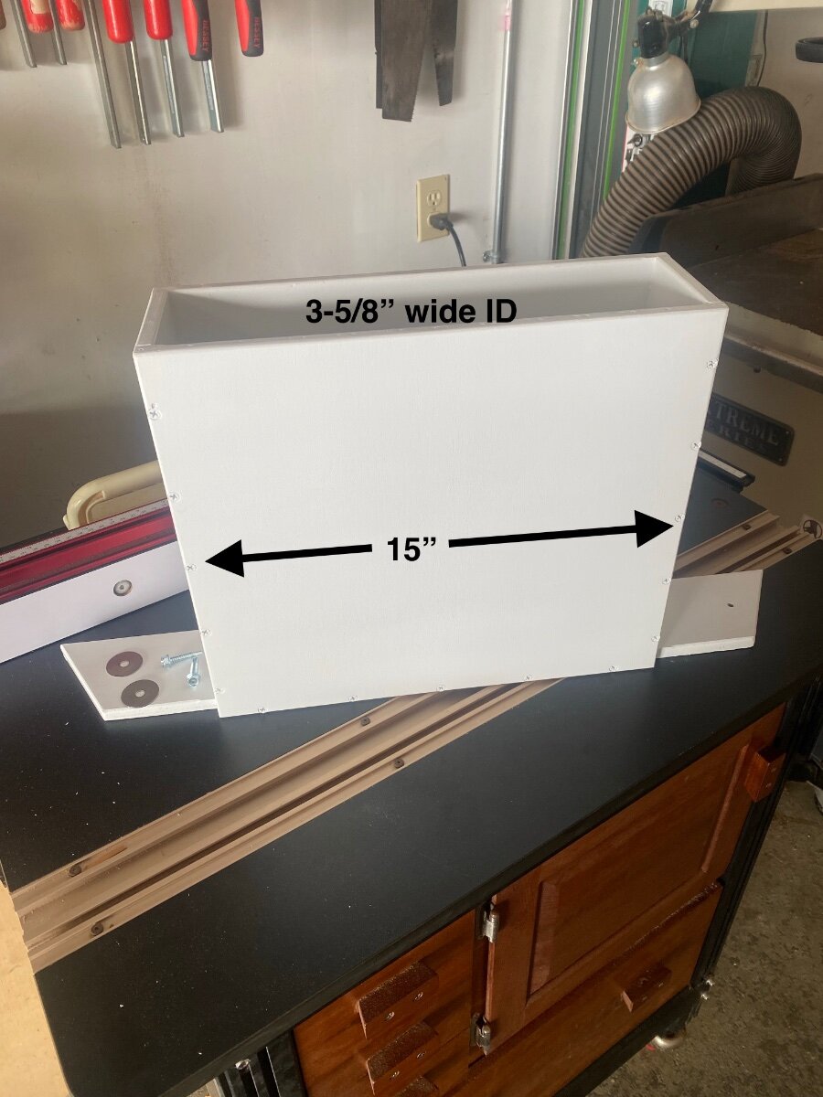
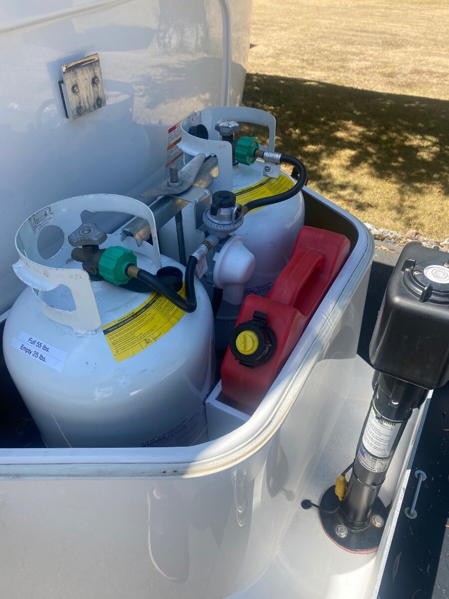
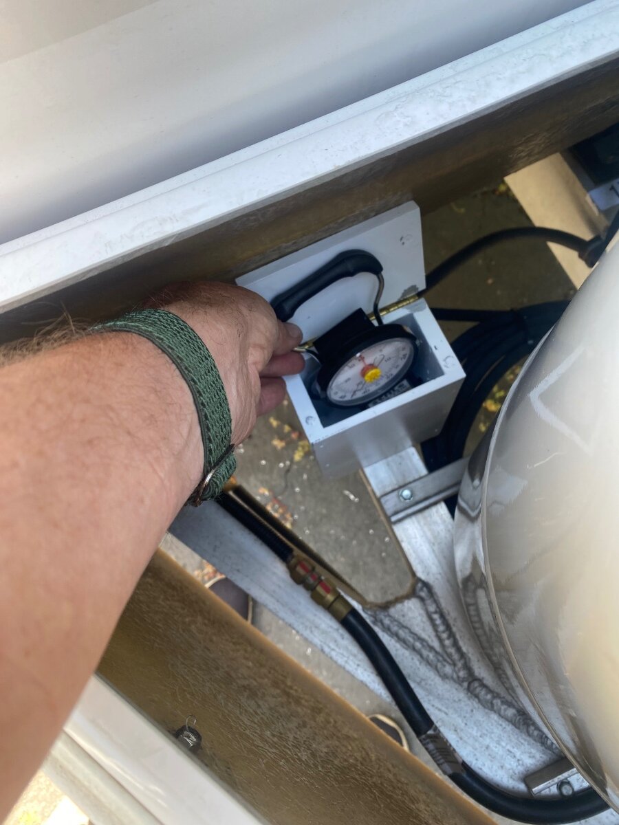
While preparing for an upcoming trip, where I’ll probably need to run a generator for AC, I decided to utilize some unused space in the dog house to store my RotoPax 2 gallon gas can. I used to carry it in the tongue tray with the generator, but now I’ll always carry it for emergency fuel. I made a rectangular box that's sized so there is just enough friction to hold the gas can snugly in place without needing a strap, and narrow enough to fit between the propane tanks and the front of the doghouse. The tank can’t come out anyway because of the doghouse cover. I measured the can after leaving it in the sun for a while to account for any expansion. The fuel can holder is made from 1/2” void free plywood (baltic birch), and it’s put together with glue and screws. It was rattle can painted with primer and plenty of white gloss, then attached to the frame with self drilling 1/4” screws, like the ones holding the propane tank tray. It can be locked through the handle if desired. The RotoPax gas cans were originally made for off-roaders, and they are pricey at around $85 each. But they are practically indestructible, and they come in different colors for diesel or water. I’ve had mine for around 7 years and it’s never leaked a drop. There are knock-offs available on AZ for about half the price, but I can't vouch for their quality. From the plywood scraps, I also made a little box for the luggage scale that I use for weighing the propane tanks. It was made in the same way with magnets to hold the hinged lid closed. It was mounted in the doghouse in front of the propane tanks. Hope someone finds this useful. Cheers! Geoff
- 2 replies
-
- 10
-
-
Haloview BT7 Touch Rear Camera installation on 2022 LEII
Snackchaser replied to dhaig's topic in Ollie Modifications
Nice work Don, very creative and well documented! Being such a handy guy, you might also like my post "Turning on the rear camera automatically." It sure beats always having to remember to flip the camera switch on and off every time. Cheers! Geoff