
Dean and Mary
-
Posts
42 -
Joined
-
Last visited
-
Days Won
1
Everything posted by Dean and Mary
-
While gathering information for this project, I also discovered that Victron has introduced a new Orion XS 12/12-70A model. It has the same footprint and mounting pattern as the 50A version but adds integrated cooling fans. Victron also slightly increased the terminal size, which should make it much easier to terminate 4 AWG wire. Getting 4 AWG wire into the terminals of the 50A version can be a challenge, so that is a welcome improvement for higher-current installations. It is pricey and I just recently purchased my 50 amp version, so not for me at this time.
-
Accidental duplication.
-
Thanks, Geoff. I appreciate all the information you've shared. I'm in the process of installing my DC-to-DC charger now, but I haven't begun working on the tow vehicle portion of the project. Your comments about the cabling requirements and the tow vehicle current sensor gave me some useful information to consider before I get started on that part of the install. I agree that the 50A Orion XS is significantly more efficient than the 30A version. Even with the improved efficiency and reduced heat output, I plan to mount my Victron Orion XS 12/12-50A DC-DC charger on top of Mobile Solar Consulting’s Orion Fan Module, which features temperature-controlled cooling. If you’re not familiar with this option, there are several YouTube videos that demonstrate the noticeable reduction in operating temperatures when using the fan module. For me, the added cooling is inexpensive insurance for a component that will often be operating under heavy load. Dean
-

Inside an Apex with Ecoflow
Dean and Mary replied to Wayfinder's topic in Mechanical & Technical Tips
I hope to be at that point within a year or less. -
Filling the freshwater tank from a container
Dean and Mary replied to Brian H.'s topic in Welcome to the Oliver Forums
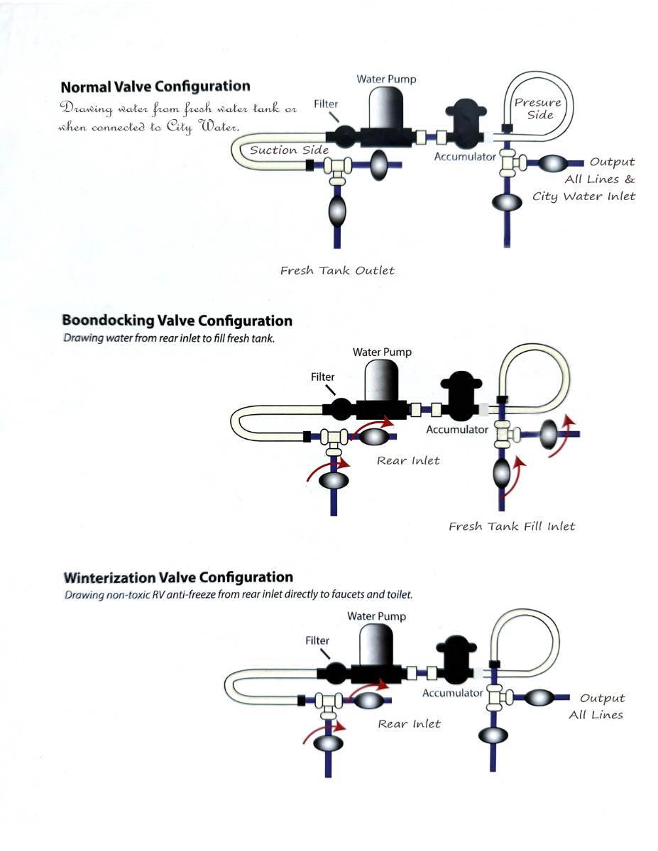
I see the source of the confusion now. There are only two water inlets on the OTT-2025 vs three inlets on my OTT-2022, and the rear inlet and city water inlet are actually the same connection. As I mentioned earlier, the fresh water inlet and rear inlet are not the same. The attached diagram from the OTT 2025 manual illustrates this more clearly, showing that the rear inlet and city water inlet are one and the same.
-
Filling the freshwater tank from a container
Dean and Mary replied to Brian H.'s topic in Welcome to the Oliver Forums
Mossemi, Providing the electronic manual for the OTT-2025 should help. From that manual, the rear inlet appears to be in the same location has my OTT-2022 model. Cut and pasted from the OTT-2025 manual.
-
Filling the freshwater tank from a container
Dean and Mary replied to Brian H.'s topic in Welcome to the Oliver Forums
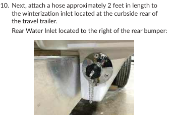
You may want to hear from an owner with a 2025 model, or a model year closer to yours. On my 2022 unit, the winterizing inlet is clearly located at the rear of the trailer near the bumper, as shown in the photo. -
Filling the freshwater tank from a container
Dean and Mary replied to Brian H.'s topic in Welcome to the Oliver Forums
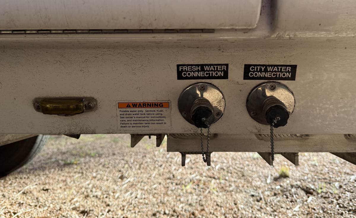
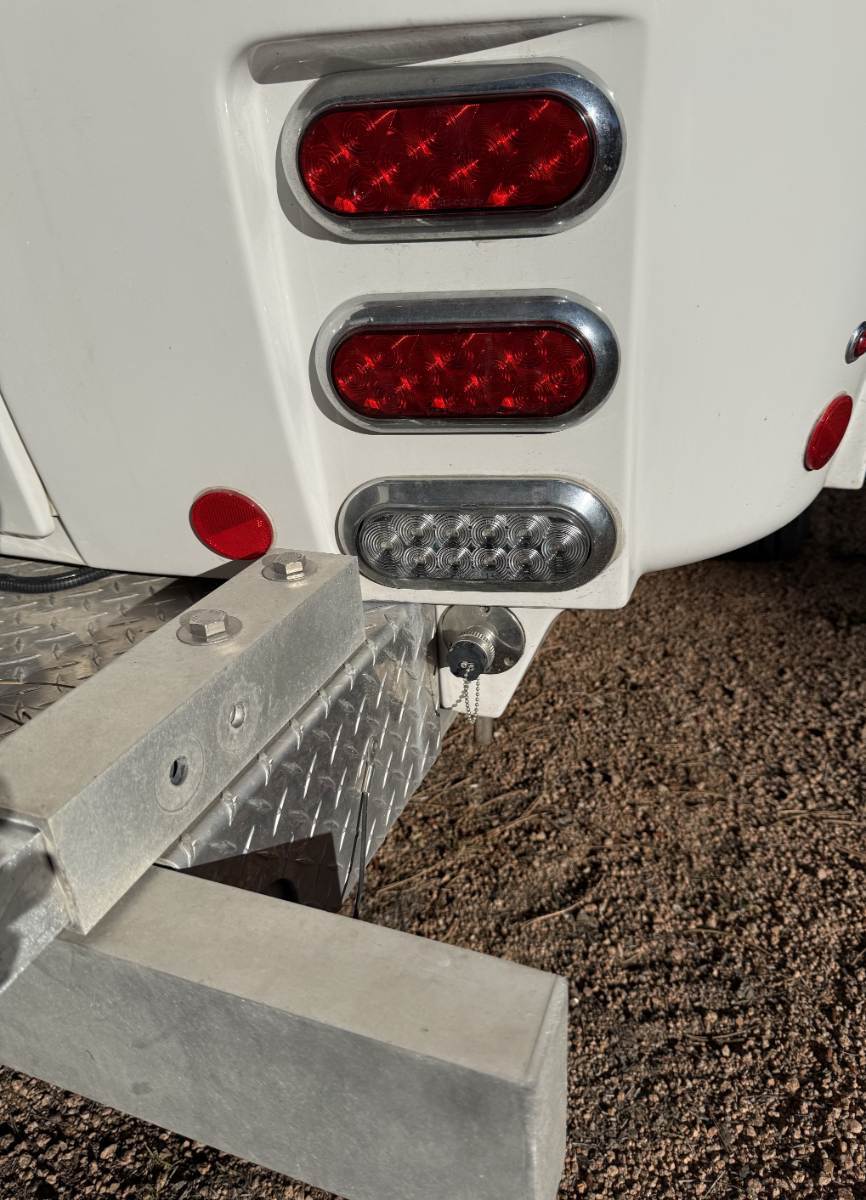
Here are two images showing those three inlets. (my camper needs a good cleaning) I hope this has helped.
-
Filling the freshwater tank from a container
Dean and Mary replied to Brian H.'s topic in Welcome to the Oliver Forums
No No, they are not the same inlet. The port that connects to the jug is located on the curb side at the very rear of the trailer, next to the bumper. The fresh water inlet is on the rear street side of the trailer, and on my unit both ports on that side of trailer are clearly labeled (fresh water and city water). When we purchased our used 2022 model earlier this year, I found the factory valve configuration diagram to be incomplete and somewhat confusing. After tracing the plumbing and verifying the valve functions, I expanded the diagram and created a revised version, which I’ve attached. In my opinion, it provides a much clearer explanation of the system and makes it easier to understand the various valve configurations.
-
Used Oliver advertisements Return to the Oliver Forum
Dean and Mary replied to dewdev's topic in General Discussion
The A/C upgrade is on our list for next spring. Before we purchase anything or begin the installation, I'll go back and review the forum discussions and your post to refresh my memory. I may reach out with a few questions once we get closer to the project. -
Buffing and Waxing my Trailer
Dean and Mary replied to Trainman's topic in Mechanical & Technical Tips
John, that’s a lot of great information. Thanks for sharing the details. This will most likely be my next DIY project. I’ve done quite a bit of reading on the forum about how to achieve the best results, and I have a Little Giant scaffold that should make the job easier, or at least safer. -
Buffing and Waxing my Trailer
Dean and Mary replied to Trainman's topic in Mechanical & Technical Tips
Hi Patriot, Your trailer looks great, and I wish I lived close enough to have CGI do some work on mine. I really like your hangar, and I have enough space on our mountain property to potentially build something similar. Would you mind sharing the make, model, and dimensions of your hangar? Thanks, Dean -
Wish we could have attended. We'll do our best to tune in for the morning coffee livestream.
-
Used Oliver advertisements Return to the Oliver Forum
Dean and Mary replied to dewdev's topic in General Discussion
I enjoy projects like this, but like any major undertaking, they come with their share of frustrations. One of the biggest challenges is having to be a contortionist to route wires in such a confined space. Being in my 70s certainly doesn't make that task any easier. Another familiar frustration is getting to a point where I realize I need one more trip to the hardware store for that specific screw, bolt, or bracket needed to finish a portion of the job. Most of my electrical components are ordered online because the big-box stores carry very little that is suitable for RV electrical systems. That often means putting the project on hold while I wait for the correct parts to arrive before I can continue. Despite those challenges, seeing the system come together and knowing it was done correctly makes the effort worthwhile. -
Used Oliver advertisements Return to the Oliver Forum
Dean and Mary replied to dewdev's topic in General Discussion
John, Thanks for sharing that your electrical upgrade took nearly 200 hours. When my project is complete, I suspect I'll be much closer to that number than to 100 hours, especially when I factor in the time spent researching products, sourcing all the required components, and figuring out the best installation methods within the limited space available in our camper. This type of upgrade is a significant undertaking, particularly when you're first removing and correcting a poorly executed installation left behind by a previous owner who hired out a smaller upgrade. I'll save those details for another post. You're also absolutely right about how much prices have increased over the past several years. My roughly $5,000 upgrade does not include batteries, as my trailer already came from the factory with 640Ah of Lithionics lithium batteries. It's hard to believe, but I've spent nearly $1,000 on cables, fuse holders, fuses, mounting boards, and other miscellaneous hardware alone. For example, a quality Class T fuse from a reputable manufacturer costs around $65, and of course I needed a spare, for a total of two. That brings me back to the original topic of allowing members to list used or surplus parts for sale on the forum. During this project, I've removed a number of fully functional components that could be valuable to other owners looking to replace failed equipment or complete their own upgrades. Providing a marketplace for these parts could help fellow owners save money while keeping quality equipment in service. -
Used Oliver advertisements Return to the Oliver Forum
Dean and Mary replied to dewdev's topic in General Discussion
I am still in the process of completing my full Victron upgrade, which has taken more time than expected. Most of the delays have been due to limited installation space and having to wait for additional, unforeseen materials such as wire, wire mesh, lugs, connectors, bolts, screws ... John made several excellent points about the simplicity of having a single display in a Victron-based system. While a Victron upgrade is a very robust and capable solution, it does require configuration and programming of the various components. If the installation is performed by a professional, the programming is typically included as part of the process. Once everything is set up correctly, the system is actually quite straightforward to operate, especially considering the level of capability and functionality provided by such a comprehensive upgrade. At least that is what I hope to find once this project is complete. One display instead of multiple apps is one of my goals in this upgrade. I've been keeping track of nearly all of the project expenses in a spreadsheet, and I'm now over $5,000 invested and more than 100 hours into the installation. Once everything is finished, I'll start a new thread with a complete write-up and details of the upgrade. -
Two weeks of feedback Apex #2 (Hull 1739)
Dean and Mary replied to Sentry62's topic in Getting Started
We placed rug gripper pads under the cushions, but they still slide off. We're going to try a different brand and hope we have better luck. -
That is a splice connector, specifically a Wago brand lever nut splice connector. Considered a good easy to use connector joining two or more wires together.
-
No worries at all! Honestly, a loose battery connection is one of those things that's so simple it often gets overlooked. We've all chased complicated problems only to find out it was something basic in the end. I'm just glad you found the issue and got it sorted out. You definitely didn't waste my time. Troubleshooting is just a process of eliminating possibilities until the culprit shows itself. Great news that you're back up and running. Thanks for letting us know what the fix was!
-
Thanks Snackchaser, that makes sense.
-
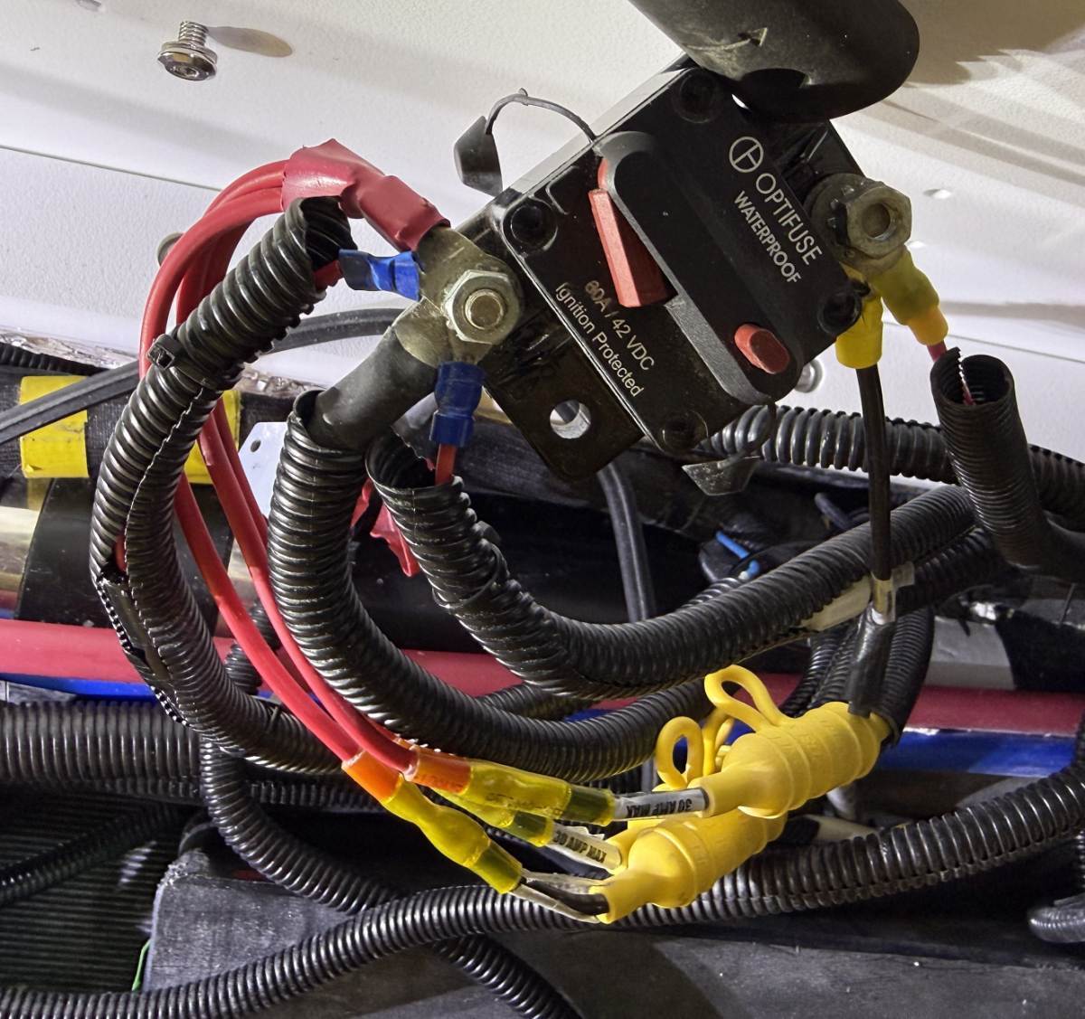
Thanks for the detailed response. I agree—the wiring is a mess, and that’s exactly why I’m redoing all of it. I did not know about the failure rate of the Optifuse. I’m also curious about the maximum of three wires on a lug, and why there are two connections ahead of the Optifuse. For my upgrade, I’ll be using the Victron Energy Lynx Distributor with ANL fuses.
-
Imelda, Thanks for the update, and I’m glad you’re able to get home with things as they are. Just a quick reminder—the jacks don’t receive their power from the converter, but more of a direct connection from the batteries through the 60 amp Optifuse shown in my above image.
-
jd, thanks for sharing the photo of your original 12‑volt distribution. It’s definitely cleaner than what my original setup looks like. I’ve attached a photo of mine—minus the 8‑gauge input wire. I’m in the middle of replacing everything and wanted a picture before I completely disassemble it. On my install, there are two wires on the input side of the Optifuse (not counting the main 8‑gauge battery feed that’s been removed). I haven’t traced them yet, but I suspect one may be for the breakaway switch. I don’t want to hijack the thread until the main issue is resolved, but identifying these wires would save me some time. I know that the heavy red wire on the output side goes to the converter and the three jack fuses are also easily identified, but I have not traced the others out. As for troubleshooting the thread creators main problem, a ground can also be found on the inverter chassis for your voltmeter. I hope all is going well and solution has been found. Dean
-
Used Oliver advertisements Return to the Oliver Forum
Dean and Mary replied to dewdev's topic in General Discussion
Topgun2: Maybe in the future we’d be interested in organizing a regional rally, but right now life is just too busy—and we still feel a bit too new to the Oliver group. Thanks for sharing the information. -
Yes, I agree—the VHB tape has excellent shear and tensile strength, and on some materials it can even be peeled away slowly when no longer needed, which makes it an even better choice.