Snackchaser
-
Posts
228 -
Joined
-
Last visited
-
Days Won
12
4 Followers


Recent Profile Visitors
1,664 profile views


Snackchaser's Achievements
")


-
12 volt heat trace is about 3 watts per foot, and I'm not sure how you would calculate the length needed to protect the hot and cold loops. We picked up our trailer during a terrible ice storm with icicles hanging off the trailer while going down the road. There was real concern of freezing pipes. We said: Damn the warnings, we're running the gas furnace while going down the road!
-
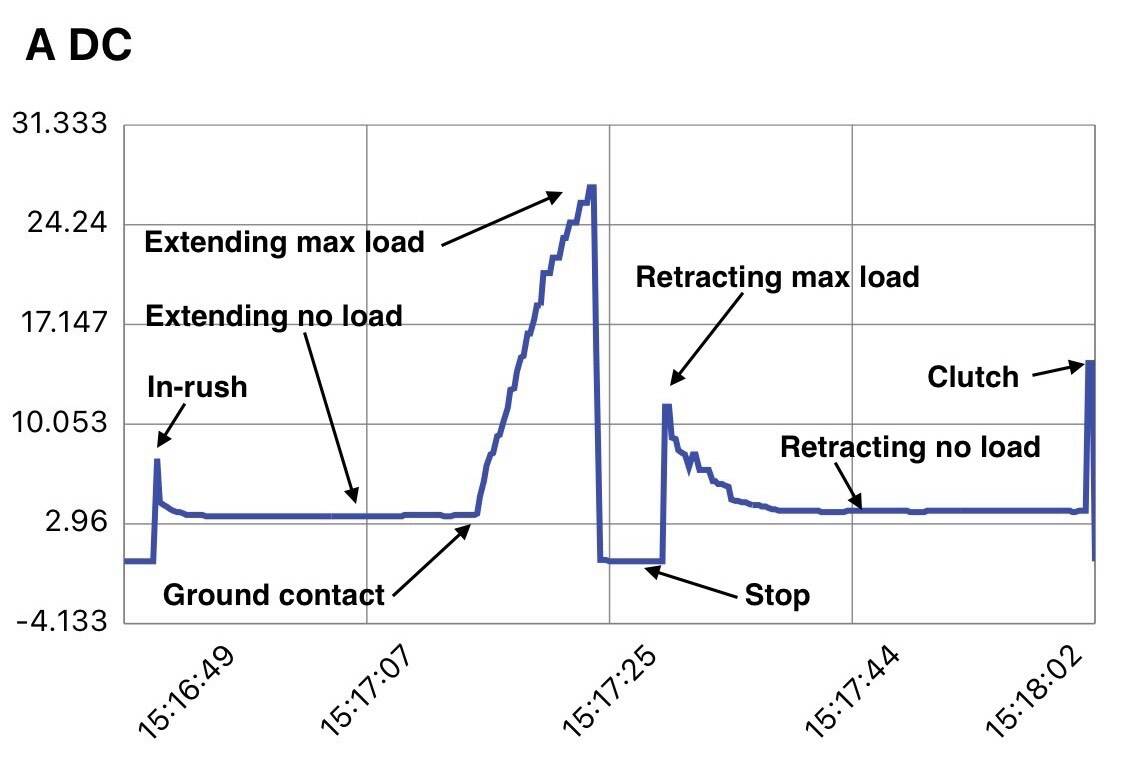
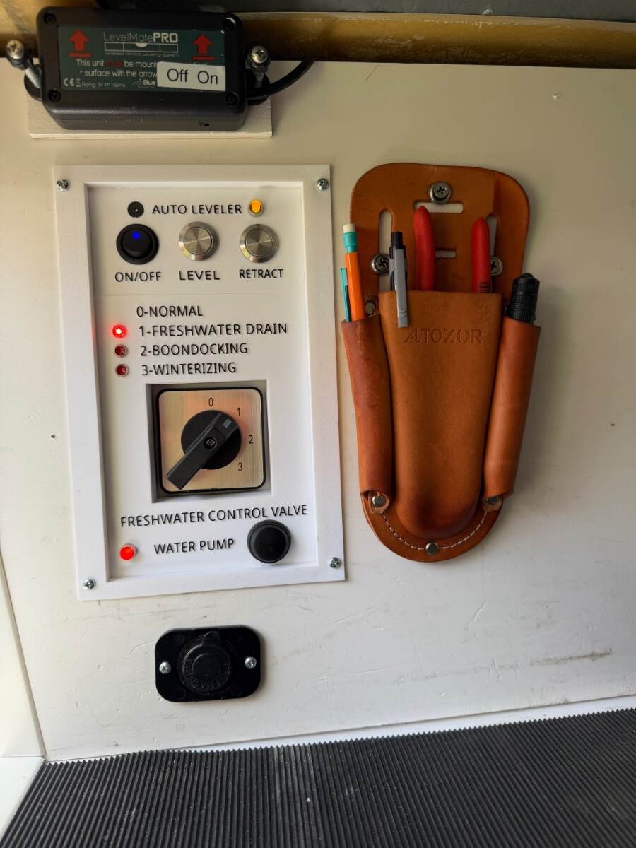
As far as I can tell, I’ve made the first automatic leveling system for the Oliver’s Barker stabilizing jacks! Maybe even the first 3-jack leveling system on a travel trailer! It’s simple to operate, safe, and works great! I built the leveling system as a novelty for my own entertainment, so I’m only posting it as a interest item not a recommended project. In reality, manually leveling with the electric jacks is already easy, particularly with a LevelMate, so automatic leveling isn’t really needed. There are even warnings that the jacks are stabilizers, not to be used for leveling. However, I believe the warnings are more about liability than capability, as long as the jacks are used within reasonable limits. I'd been thinking about an auto-leveling project for a long time, but was deterred by the thought of modifying the jacks with fiddly proximity sensors or revolution counters as used in conventional leveling systems. I didn't want to alter the jacks for a DIY project that might not even work. But then it dawned on me. The only time I really needed to know the position of the jacks, is when retracting them to their parked position. I wasn’t interested in returning the tongue jack to the truck hitch hight like some systems offer. So this led to a revelation that automatic leveling could be done with nothing more than current sensors mounted in a control box rather than on the jacks themselves. This was only possible because of the Barker jack’s mechanical clutch. When the jack reaches the end of its travel, the clutch activates with a distinct clack-clack sound. It was likely that clutch engagement would produce a unique current signature that could be used to detect when the jack is fully retracted. A plan was developing, but I needed actual amperage values for proof of concept. Fortunately I had a data logging ammeter, and the chart below illustrates the results for one of rear jacks starting from its fully retracted parked position. The jack was extended through free air until it touched ground and began picking up load, maxing out when the wheel lifted off the ground. Then it was retracted to the parked position until the clutch actuated: I didn’t include the tongue jack chart because it's far less dynamic — it's always under load, and the clutch doesn't normally actuate during leveling. The clutch only comes into play after trailer is hooked up to the TV and the tongue is manually retracted. The amperage results confirmed that current sensors could work, and beyond detecting the parked position, they could also be used to distinguish the different leveling phases: rear jack extension until firm ground contact for stabilizing, and then transition to "roll" leveling if needed. Completion of the rear jack phase could then trigger the tongue jack phase to handle "pitch" leveling. The amperage chart became the basis for the circuit and software design. No proximity sensors. No revolution counting. No permanent modifications — just two wires to each jack, a component box, and a control board. Sounds easy, but this was only just the start of a long process to perfect the system. I hope someone finds this interesting! Cheers! Geoff

-
- 7
-

-

-
Water pump runs continuously after tank sanitization
Snackchaser replied to Sandman's topic in Welcome to the Oliver Forums
The pump stops running when the pressure set-point is reached. So it’s pumping, but not reaching full pressure. This happens when there is a leak on either the suction or output side of the pump. If the leak is on the output side, it’s easy to find because it will be leaking water. However, if it’s on the suction side, it will suck air but it will not be leaking water. The most common cause is the suction side filter right next to the pump. You won’t see any signs of leakage, but make sure the cap is on straight and tight with o-ring. I assume you have re-checked proper valve line-up and full closure, and any open faucets. Other than that, it’s unlikely a leak developed by just sanitizing. Good luck, Geoff -
Maximizing amp hours for boondocking
Snackchaser replied to Olive2Roam's topic in General Discussion
As JD said, the inverter should run the microwave. Three things you should try first: 1) Using the Xantrex App or control panel, check/lower the low voltage drop out. It's usually set between 12 and 12.2 volts. Try lowering it to 11.5. The battery voltage will drop under load, and there could be voltage calibration errors in the inverter so that if it's set to 12.2, it could actually be higher. 2) Also check/increase the low voltage cut-off delay. The delay prevents nuisance trips from inrush currents, and the microwave might have a delayed power surge. 3) Try a hard reboot. This has worked for some folks, but it's more difficult because you have to disconnect the battery leads for a few minutes. Hope that solves the problem! Geoff -
Lithionics large phantom draw
Snackchaser replied to DaveAndBecky_NorthernMI's topic in Mechanical & Technical Tips
Check to make sure that your brake "breakaway switch" wasn't accidentally pulled out. If so, the electric brakes have been on the whole time. Four brakes would draw 3-4 amps each. If you were reading 2-3 amps draw on your Lithionics battery App, then that's only one of the 3 batteries. So it's actually 9-12 amps. Add in the solar input and it's about right for what the brakes would draw. Good luck, Geoff -
Amazon carries it, but theirs is sometimes low quality and thin. I got some from an HVAC contractor/supplier for free. It is used for duct insulation and was much better quality.
-
Yea sorry, those Amazon links were questionable, so I updated that reply with a better link. 3-pin dc power connectors are typically switched, to disconnect a battery when an outside power supply is plugged in. Those Amazon knock-offs have a sketchy description, so without actually testing one there is no telling what they are. I buy parts from DigiKey. Look up Digikey part PJ-005B and view the datasheet. There is a schematic showing the Pin-2 to Pin-3 switch. They are under $3 at DigiKey plus shipping, Amazon sells them 5 for $18 with free shipping: https://a.co/d/04TQyt2M
-
Edited to correct link. Here is an updated Amazon link: https://a.co/d/04TQyt2M
-
Ruuvi sensors with Victron - Awesome!
Snackchaser replied to rideadeuce's topic in Ollie Modifications
Just as an FYI, new tech is out there! Although probably impracticable for most, others might love the Safiery LP tank sensors! Check out today's new post "AI is here for your trailer!" Cheers, Geoff -
There are plenty of posts about new products and technologies for our trailers in this forum, and it seems there are endless choices. But for those willing to pay for cutting edge and high quality, take a look at products from Safiery. Safiery, based in Australia, began as a Victron supplier and is now marketing their own RV and Marine products to integrate with Victron equipment. It’s a somewhat confusing array of technology that is mostly overkill for our little trailers. But I’ve been eying a few items that look very attractive: Since I titled this post with “AI tech,” then I should mention Safiery’s Smart AI DC-DC charger. Cutting edge for sure, but not cost effective for small systems IMHO. If I was looking to upgrade or replace my lithium batteries, the Safiery SOLID STATE batteries are worthy of consideration. They are expensive, but cheaper than the Oliver’s Lithionics, and they have many advancements such as 10,000 cycles, improved BMS, better cold performance, smaller size, more robust, and much safer than liquid lithium. For those with Victron Cerbo, Safiery has compatible tank level sensors for liquids and LP gas. I had been waiting for something like this before upgrading to a Cerbo. These sensors are easily adapted and competitively priced with some of the lessor alternatives. Liquid tank sensors are top mounted and use Radar for very accurate measurement, LP gas level sensors are similar to Mopeco, but with built in signal processing. How about an Electric Stovetop? A safiery induction countertop stove looks very cool and affordable for those with 2k inverters (can be drawer mounted too!). Then there is a whole array of digital wireless switching options with Multi-channel receivers, bus management, and other options I haven’t even gotten around to looking at yet. It’s an exiting new world for the tech minded DIYer! Cheers! Geoff
-
- 2
-
-
I'm not sure what vintage the old unit was? However, I recall that there was some question whether it was an AGM only battery charger. So if your new replacement has charge profiles for both AGM and Lithium and you want to retain the lithium option - then it's not worth keeping as a spare. Besides, no telling if the resistor is the only issue. Glad you're whole again! Geoff
-
I haven't examined these shades in this regard. However, I believe this would be a good job for a 3-D printer. A glued or snap-on shade could be drawn in free CAD software, such as Tinkercad. The drawing can be saved as an STL file (for 3D printer) and shared in any of the free design sites such as Thingiverse where anyone can download it. If you don't know someone with a 3D printer, there are plenty of local and on-line services that would print them for a small fee. Shades could be printed in any of the numerous available colors and materials. Basic PLA (plant based plastic) or ABS would be perfect. You could make it more stylish than a pipe fitting, and refine the shade thickness to diffuse the light without glare. This would require experimentation to get it right. I'm not overly keen on the idea, but if you want to sketch something up to get started, I'd be willing to collaborate with you to design a decent shade. I have plenty of white PLA and white ABS on hand for prototypes. Cheers! Geoff
-
Hey Fred! Even with all the other options now availible, this Starlink Mini power supply is a great way to go! I provided Amazon links to the Victron, timer, and programmer to someone else above, and the links are still good. As far as the 3-pin connector, there are several choices on Amazon. Search for 5.5mm 3-pin DC power connector. Go to timers.shop website for programming instructions. Iv'e provided a screen shot of the settings above. The programer is powered by USB, and the settings are flashed to the timer via WiFi by a cell phone or computer, No Apps are required, just open the URL address and plug in the settings. Have Fun! Geoff
-
Ron, You've had good advice to check the converter fuses. If that is not the issue, then iI's time to break out a voltage meter. 1) Disconnect shore power, and your battery tender, then check voltage at the battery (it's probably the 12.4 as you were seeing). 2) Reconnect shore power and check voltage at the same location, it should be higher which would indicate if your converter is converting and charging. If not, the converter is bad. Update: I looked at the converter manual link from above. The converter has 3 stages of output, each with a different voltage of 14.4, 13.6 and 13.2. One of those voltage values is what you should see when you test the battery on shore power. The manual also has a section that describes a simple test to absolutely confirm it's faulty before replacement. Be mindful that electrical problems are elusive and tricky, so the manual's test is important. As Jd suggested, the batteries are older and you could upgrade to lithiums. That would be a big improvement. However, unless there are pages missing from the manual, it looks like your converter is for lead acid batteries only. So if you upgrade batteries, also upgrade the converter. Fortunately, repair kits are available to replace the converter/charger section of the older PD units, and that also upgrades them to lithium chargers at the same time! Also, you would need to check/set your solar charger profile for lithium batteries. Looks like you're making good progress! Geoff
-
Okay, shore power looks good, but battery is dead! Sounds like you had been using outdoor solar to keep the batteries charged, then moved the trailer into the garage where there is no solar charging. If you didn't have shore power connected right away, then normal parasite power could have drained down the batteries and they just haven't had enough time to charge yet. A deeply discharged lead-acid battery looks almost like a short circuit to the charger initially. The battery voltage is so low that the converter/charger dumps maximum current into it trying to bring it up, which could cause brownouts both on the AC and DC power circuits. Deep discharge cycles and age can also degrade batteries, so they may not be charging, or they could be acting like a short. A faulty converter/charger can cause similar issues. It could have been weak or bad for a while, but un-noticed if you were solar charging. They can degrade and still work, but at a lower output. Where are you reading voltage? This could provide clues. To answer your question, yes a tender will charge both of your batteries at the same time. That would be a good next step.