
Snackchaser
-
Posts
297 -
Joined
-
Last visited
-
Days Won
20
Everything posted by Snackchaser
-
There are lots of Olivers with the keyless RVLock so I thought it's worth sharing our good experience with this great company. We decided to install an Amazon-purchased RVLock keyless door handle ourselves instead of buying it as an Oliver option. The installation was quick and easy, and it comes with a generous lifetime warranty. The locks are made in Utah by a small company, and they look and feel like a quality product. Unfortunately, however, there have been issues with the electronics because it has failed three times already! It first failed after about six months, and I called the company for the warranty claim. They wanted proof of purchase, then sent a replacement KPD keyboard and PCD circuit board with installation instructions. We were able to look up the receipt on Amazon and received the parts in a few days. It failed again about a year later, and RVLock still had me in their system. They immediately sent more replacement circuit boards with a new rubber keypad cover. This time, I applied sealer around the lock even though there were no signs of water intrusion. Unfortunately, it failed for the third time a few weeks ago. The RVLock company’s customer service was apologetic and said that they’ve done some design changes to address the problems. This time, they sent upgraded circuit boards, a new speaker circuit board, a foam gasket, and instructions. There was a shipping charge of $3. I hope that this is the final fix because we genuinely love the lock and we wish success for companies that stand behind their products. Cheers! Geoff

-
Recommend a clamp meter that will measure DC amps
Snackchaser replied to a topic in Mechanical & Technical Tips
Well not completely! Clamp-on amp meters are great tools for RV owners, and many double as multimeters too. But it’s important know the differences and limitations to make an informed choice of which meter will meet your expectations. Clamp-ons are great for measuring higher currents, such as battery chargers and power feeds. But they're not great for measuring low currents, such as branch circuits and parasite loads. They don’t have the resolution needed for lower amps, and they can be finicky if not positioned just right. If you plan on measuring small currents, then get a basic Multimeter with a shunt type ammeter. They measure "in-line" with the current, typically up to 10 amps (+/- 1 milli amp.) Some clamp-on meters with built in multimeters, such as the Klein CL390, also include a shunt type amp meter. But check the specs because a lot of these are in microamps, which is too low for an RV’rs needs. Amperage is subjective of many factors, so if you're really serious, consider a $$$ data logging meter to see whats going on over time. The Victron smart shunt also has data logging (+/- 10 milli amps.) You can use it to measure the current of various loads by isolating the circuits and inputs. Having said all that, I recommend getting both a Clamp-on ammeter and separate Multimeter to cover all your amp measurement needs. You will probably be reaching for the multimeter most of the time. If you want some Oliver real life examples of ammeter accuracy, and how to measure parasite loads, see my post in the topic “Battery depletion rate 3% or more per day... with EVERYTHING off?” My post is way down on the third page with photos. Hope that helps, Geoff -
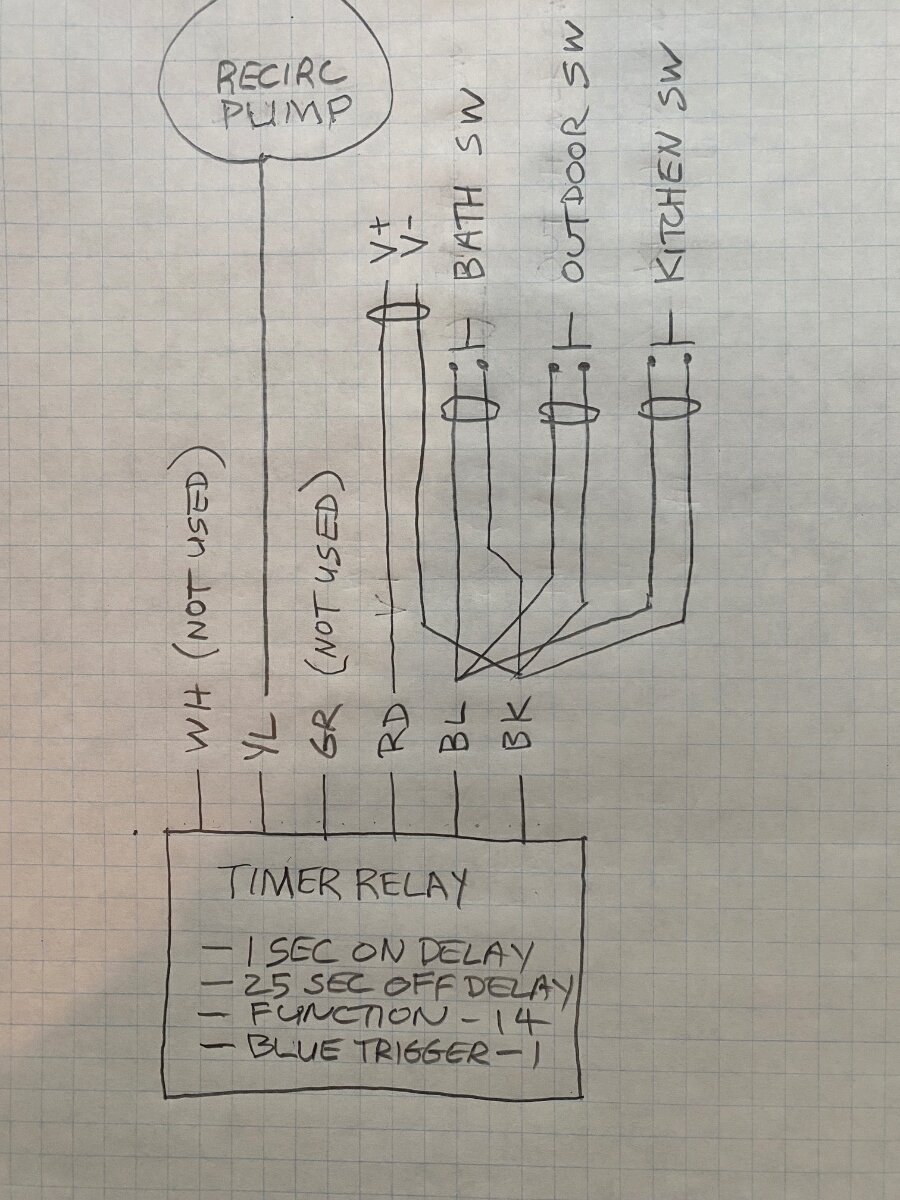
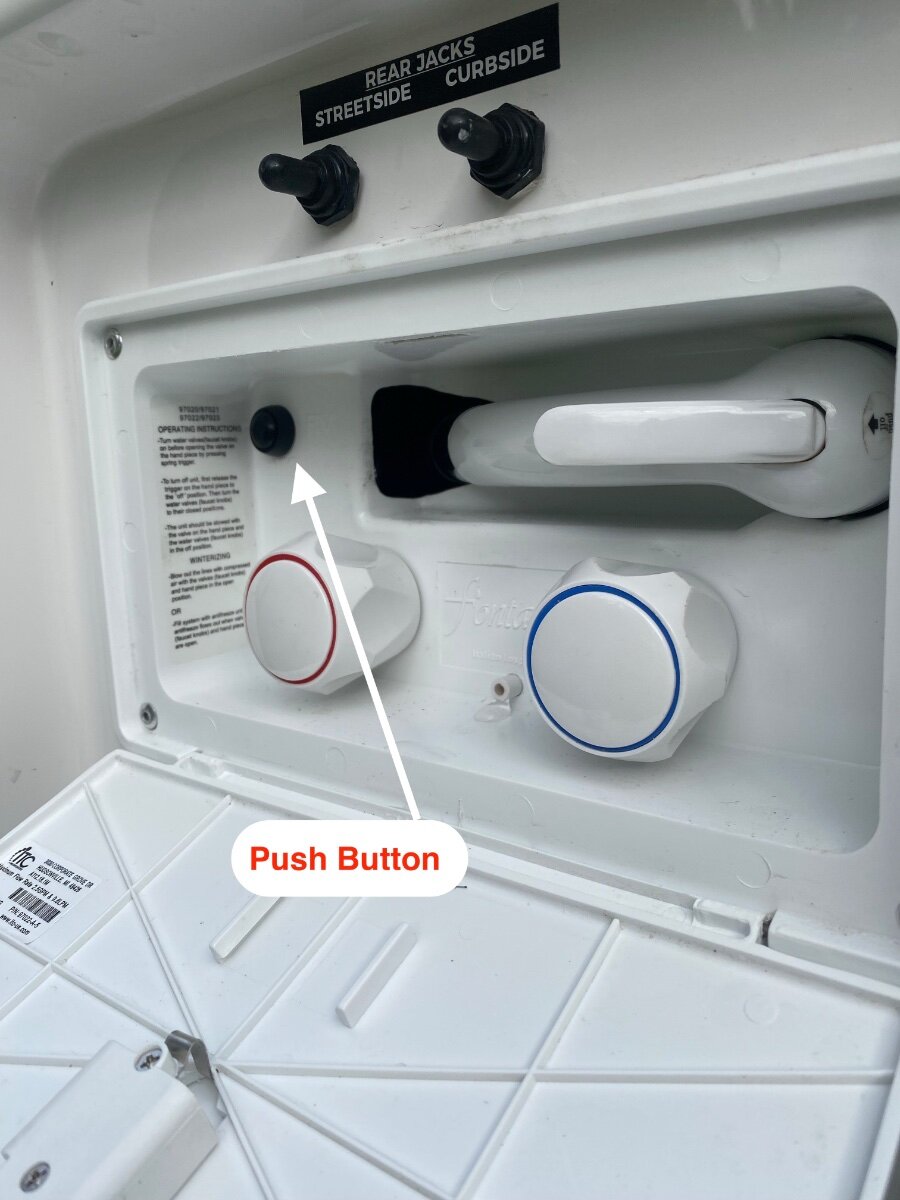
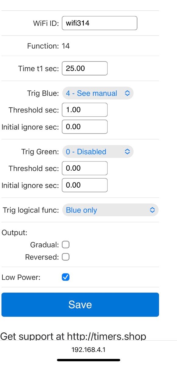
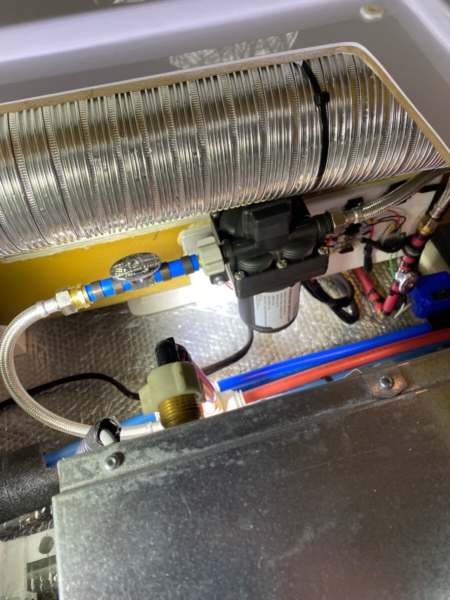
This is yet another modification for instant hot water. I was inspired by @Minnesota Oli who brilliantly installed a timed solenoid valve to circulate hot water from the bathroom faucet back to the freshwater tank. This saves from wasting water down the drain while waiting for it to get hot. I loved the concept of using a timer, but I went with a recirculating pump instead of a solenoid valve. We’ve used this design for about a year now, and it’s been very luxurious and effective. Not only does it help conserve fresh water, it prolongs the grey water tank volume which is now our most limiting factor when boondocking. The recirculation pump is started from momentary push button switches installed at each faucet. The button(s) activate a timer/relay that runs the pump for 25 seconds. Experimentation showed that 25 seconds sufficiently heats the pipes to deliver hot water at full temperature. The pump circulates the hot water back to the hot water heater, rather than into the fresh water tank. The new recirculation pump is the same model as the existing main pump. It was connected with flexible faucet hoses to reduce vibration and isolation valves so it can be used as a spare if needed. The pump was mounted on a plywood board fastened with construction glue to the vertical fiberglass surface by the furnace return vent. Note: Pump pressures can vary, so it might be necessary to slightly adjust the pump pressure switch to overcome the house pump pressure. Also, the pump may not overcome some of the higher city water pressures if a pressure regulator isn’t used. . . as it should be regardless. The Oliver has two separate hot water loops that I joined together so that the kitchen faucet is included in the recirculation loop. Being a shorter loop, there was less water wasted while waiting for it to get hot, but it's used more frequently so it's worth it to join the loops. There is plenty of room under the floor and behind the cabinets to run PEX return lines. “T” fittings were installed at the kitchen and bathroom faucets, and at the water heater input as shown on the drawing. Note: There was a buried 3-way valve, flexible by-pass hose, and a (clogged open) check-valve for water heater isolation. It was restricting flow and pinching the furnace duct so I completely removed it. The Water Heater can be easily isolated other ways if the need arises. The momentary push buttons were arbitrarily programed so that they must be depressed for one second before the pump will start. The buttons were non-intrusively mounted in 1/2” holes. The bathroom button is behind the existing bathroom pump switch, the kitchen button is above the sink, and the outdoor shower button is inside the shower wand enclosure. The sheathed button wiring is joined together under the street side bed along with the timer. I used terminal blocks, but wiring could be joined with any number of splicing methods. The button wiring carries no measurable voltage or current, it’s simply a switch to “low” (ground) for the timer trigger. Wire runs to the bathroom and outdoor shower switches are pretty straight forward, the bathroom vanity shelf needs to be removed for access. The kitchen switch wiring is laid under the liners in the upper cabinet, through the attic, and down the rear wall next to the clear AC drain tubing. I used a programmable timer/relay for the pump. An inexpensive (re-usable) Programer is also needed to program the timer. The Programer has built in App and Bluetooth for programing it on a smart phone and I’ve provided a screen shot of the program settings. This is truly simple to do, and quite fun! As many in this forum know, the Tuma Comfort II water heaters have a built-in circulation pump, controlled by temperature sensors, that keeps a small internal tank ready with hot water. Only one part (unavailable to public) differentiates it from the Truma Comfort II “Plus” that has a full hot water recirculating system. It took a few years, but I finally have the design details for that part and I’ll try to fabricate one when the Truma is removed for the up-coming factory recall work. More to come if I’m successful. The Truma “Plus” recirculation system provides true instant hot water (when not in Eco mode) because it keeps hot water circulating through the system based on temperature sensors. My system has a 25 second delay before the water is hot, then it cools down until the button is pushed again. This is less convenient, but more energy efficient because it doesn’t periodically cycle. I’m still on the fence which system is better, but fortunately the recirculation loop installed in this modification will work for both systems. Hope someone finds this useful! Cheers! Geoff Shopping list: Sureflow pump https://a.co/d/cSLUWEF 10 amp Timer/Relay https://a.co/d/g6C1zaZ Timer/Relay Programer https://a.co/d/9h1HtK6 Momentary switches https://a.co/d/i9wwhNs Terminal Blocks https://a.co/d/bkgrKhh Red PEX and fittings Flexible faucet hoses 1/4 turn valves
- 1 reply
-
- 12
-

-

-

-

-
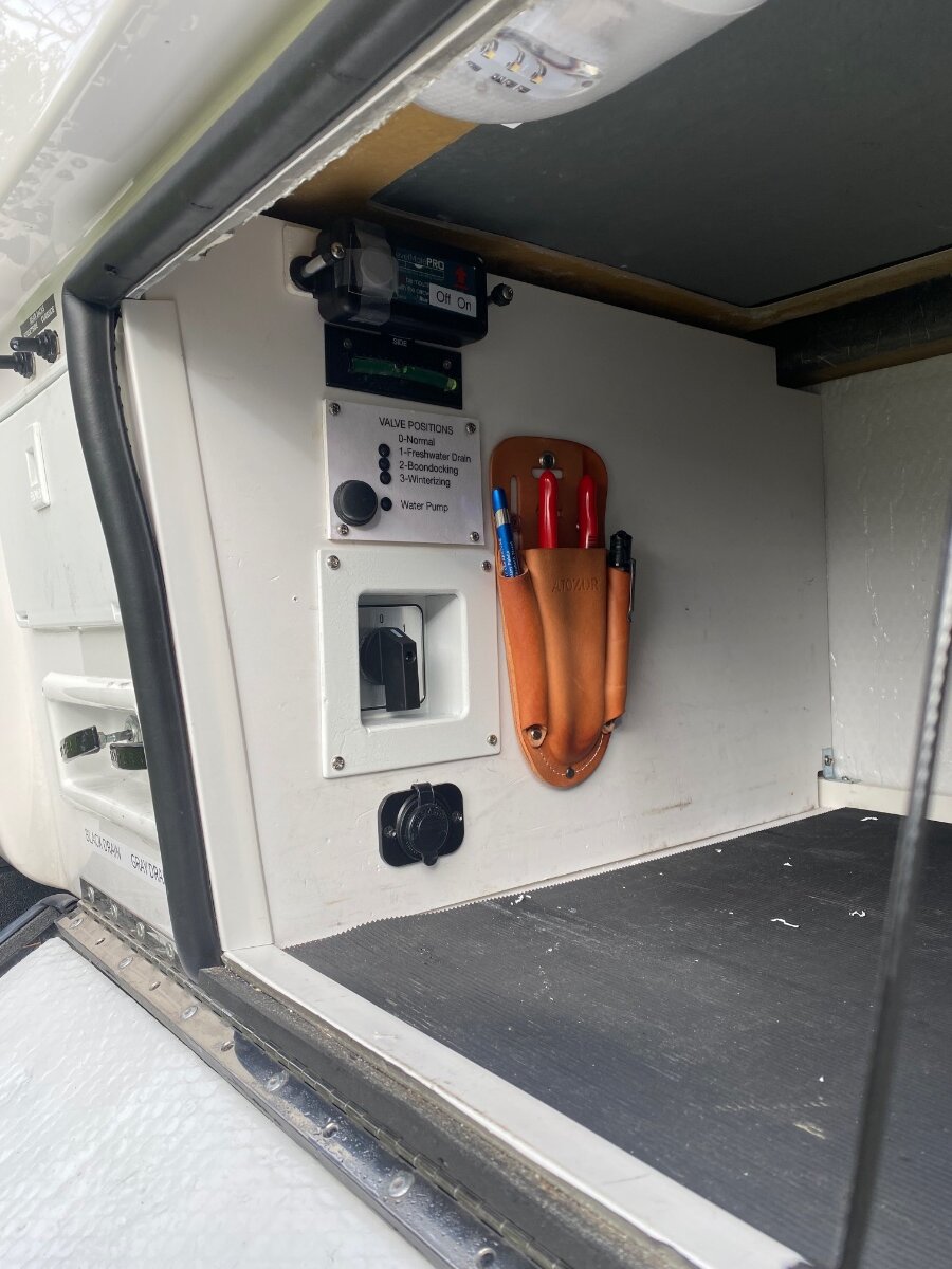
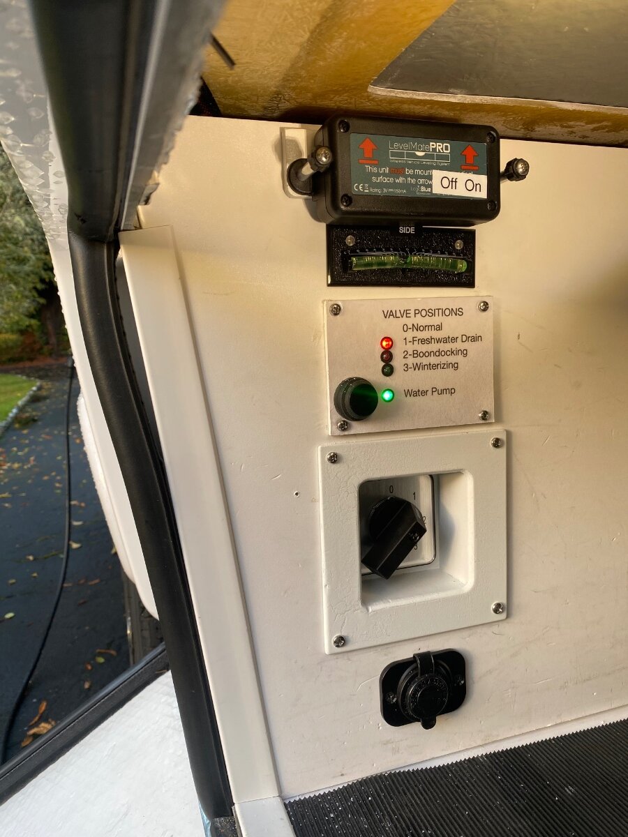
Thanks! And I see how that poor quality photo could raise questions from observant folks. Only the spirit level was installed by Oliver. The bottom item is a 12vDC outlet for a macerator pump. Next is a rotary switch for electric valves that are used for freshwater tank drain, boondocking and winterizing line-ups. It’s described in the post “Electric valve control… with a twist.” Then there is a third water-pump switch for the outdoor shower, or when filling the freshwater tank from the boondocking port. This is described in the post “4-way pump switch for the outdoor shower.” Above that, are labeled LED indicators for the aforementioned pump and valves. Lastly a Levelmate with lengthened thumb screws for easy battery changing. They do look like toggle switches! Then my trusty pliers. . . they actually replaced quick disconnects that I found were too bulky and inflexible for my needs. Cheers! Geoff
-
Could be a number of different things, but it wouldn’t have anything to do with the circuit breakers or park power. The fault will be at the GFIC outlet, or one of the downstream outlets fed by it. GFIC’s are not overcurrent devices, rather they detect minute circuit imbalances where either the hot wire or neutral wire is leaking current to ground. So one of the most common problems is moisture, usually in the outdoor outlet/box. Make sure the cover seal is good and dry it off as best you can. Another common cause is improperly wired devices, so make sure everything is unplugged. If that doesn't fix it, then disconnect the "load" side of the GFIC outlet and see if it’s still tripping. If so, then replace the GFIC. If it doesn’t trip with the load disconnected, the GFIC is okay and I’d go back to the outdoor outlet and really dry it well. Good luck!
-
Nice! I think I'd need several sets!
-
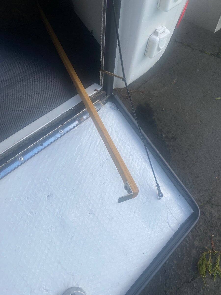
When doing hook-ups or departures from camp, I regularly find myself in need of water pump pliers to tighten and loosen water lines. . . which means digging out the tool box to find them. So I decided to mount a dedicated pair in the outdoor garage where they will be close at hand when needed. After looking at various options for storing the pliers, I settled on a small leather tool pouch from Amazon. It was low profile, could be easily mounted on the wall, and it didn’t take up precious garage floor space. The pouch also had pockets for a small flashlight and pen, which also can also be elusive items when signing in after dark. The tool pouch had a belt clip that was removed, and I stretched one of the pockets to fit my LED penlight. The leather is easily stretched by soaking it in water for about 60 seconds and using a dowel or other cylindrical object to expand the pocket. The leather is quickly dried in an oven at 130 degrees to hold the new shape. I chose a 7” Knipex Plier Wrench for my kit because of its high quality. They aren’t cheap, but the Oliver is deserving, and they are a pleasure to use. There are many excellent choices available for pliers, flashlights and pens. I just used what I already had on hand. Some folks might also be interested in my handy tool for stashing and retrieving things from the unreachable depths of the garage. This is simply a sanded length of 1/2” x 3/4” moulding with an aluminum angle screwed onto one end as a hook to pull things out. Oh, and notice the spring to pull the garage door suspension cable out of the way so it doesn’t get pinched in the seal like mine does. Hope you find this useful! Cheers! Geoff
-
Truma water heater repair #3
Snackchaser replied to Galway Girl's topic in Mechanical & Technical Tips
I don't know about the noises, mine makes just a little noise. The circulation pump keeps hot water in the small reserve tank, so it's turned off to conserve power and gas in the ECO mode. Good luck, Geoff -
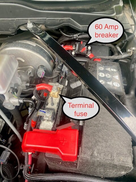
True. . . but they were terribly misleading because the circuit is energized directly from the battery, regardless if the alternator is charging or not. Think of it like a jumper cable connected to the battery, if you were to brush the red cable against any grounded surface of the vehicle then you're going to have big sparks like a welder . . . before any thermal fuse will blow. A circuit fused at 60 amps has significant potential and I think it would be somewhat negligent not to have a quick and easy means to disconnect it, as is the law in other applications. It’s straight off the battery, always energized, running the length of the vehicle, with a connector exposed on the rear bumper. Most mechanics wouldn’t have any idea what it is, and may not take precautions to avoid it. I love @Tom and Doreen idea of using a high amperage switch instead of a breaker. The switch is more obvious and it would do a better job at alerting someone of a high potential than might need to be shut-off. I’m keenly aware that I’m too forgetful, and I may not always be around. Cheers! Geoff
-
No more chasing snacks in the dark!
Snackchaser replied to Snackchaser's topic in Ollie Modifications
Yes, the snacks are missing!!! Wifey has been notified and I can neither confirm or deny any involvement in their disappearance! -
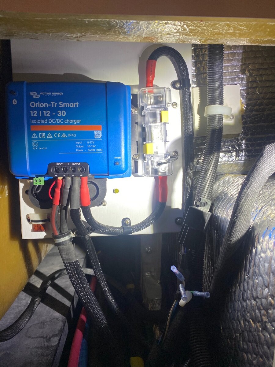
I also used a Blue Seas MRBF 60 amp fuse, and I added a redundant 60 amp breaker just as a disconnect switch. The Orion output has a #7720 Blue Seas 60 amp fuse block, rather than a breaker. Just as a FYI: A breaker has polarity so it only protects the wire on the load side. In this unique application, you would have to decide if the breaker will protect the wire from the massive Oliver battery current potential, or from the 50 amp Orion charger potential. Whereas a fuse has no polarity, it protects the wire from both potentials.
-
John, good discussion! The Orions protective features are based on voltage rather than amps, and alternator voltage will drop in an overcurrent current situation. Thats one of the Dropout Voltage functions, it protects the alternator from overcurrent. The Orion allows you to adjust the Dropout Voltage enough to compensate for cable voltage drop, but not enough to lose the alternator protection or engine-on detection features. I was pleasantly surprised when getting 35.8 amps output from the Orion, but it is capable of 40 amps. With the 42 amp input, it equates to 85% efficiency, where Victron claims 87%. The difference in my output / input amps can be attributed to both efficiency and cable voltage drop because even with #4 we are undersized. Okay I see whats going on, you have a “non-isolated” Orion! So the b- current is divided between the #4 wire and your frame. Those angry pixies will always take the path of least resistance, so as you rightly pointed out, the wire is taking 75% of the load because the frame resistance is higher. I hadn’t considered that because I use an isolated Orion and it carries the full input current on the wires only. I don't think it's a problem for you, if anything, it's helping. Humm? The 50 amp Orion is non-isolated too, so JD would be well served to buy an additional 12' of wire for the truck b-, and get a performance boost at little extra cost🤙 Good stuff man!
-
Geronimo, JD, I also have the 30 amp Orion with around 90' of #4. With the TV at idle, and the lithium batteries around 60%, the average TV input to the Orion was 42.5 amps, and the Orion's output to the battery was 35.8 amps. Decent efficiency! Amperage flows equally in a loop, so the B+ and B- will always be the same value. Knowing that, the 25% difference that you were seeing between measurements was most likely due to the Orion auto adjusting the battery charging current, or changing the output current due to low voltage, or even the smart alternator searching. It's really hard to get a consistently stable amp reading with all that going on. The Victron smart shunt has a log feature that might provide a better overall picture of its performance. You have 18' more wire than me, and that will increase resistance and voltage drop more than it may seem. It sounds like you might also have some added resistance from using the frame through the hitch for B-. That can cause the Orion to reduce the output amperage, which reduces the voltage drop, which brings it back within the default set points. So it might help to change your Orion's default “Start Voltage” from 14 to 13 volts, and the “Shutdown Voltage” from 13.1 to 12.8 volts. I get into more detail in my post "More DC to DC charger Installation Tid Bits." You might also re-check the battery type settings while you're at it. A cooling fan would be good for the 30 amp Orion, especially considering it ramps down 3% for every degree above 104 F. I described a way to install fans using a 104 degree thermo switch so that it doesn't create a parasite draw. It's also in the afore mentioned post. FYI, I was checking into adding parallel wires with the existing #4 for a 50 amp Orion upgrade. Geez, I'd have to add at least a #1, but better a #1/0 to stay within acceptable voltage drop. That's a lot of trouble and expense so I'm going to stick with the 30 amp for now. I'm very pleased with its battery charging performance, but not so much for running the AC. Hope you will find this useful! Cheers! Geoff
-
What is your cell phone speed without the Pepwave for comparison? The DC to DC charger will not work in reverse, otherwise it would charging the truck battery. The Victron is still a good option when using the Starlink supplied 50’ cable, which is really desirable when trying to find clear sky view when camping around trees. Starlink now offers a 16’ USB cable for in-motion use that would be a better option for the truck.
-
Awe thanks, but you probably know more about it than I do! There is great information about using a Pepwave with Starlink on the YT channel “Mobil Internet Resource Center.” People primarily use them for better reliability and stronger WiFi for increased speed, and they would certainly supplement the 50 GB Starlink roaming data plan. The Starlink Mini’s built-in router is not as powerful and the speed decreases the further away it is. We usually get 100 to 150 mbps with the mini compared to reported speeds of 300 when using aftermarket routers, which is about the same as our Gen-3 dishy at home. However, 100 mbps is still a respectable speed. We’ve exceeded the 50 GB limit a few times. So we just pay for the extra GB’s as we go. The real expense is the extra snacks and cocktails for internet mooching visitors 😉 I seen Starlink dishy’s laying flat, but not a Mini so far. Not to say it wouldn't work! I think orientation is more important for them because of the small surface area. The kickstand and pole mount are angled and the Starlink App lets you know if they’re not pointed in the right direction. Which seems odd to me because the Mini is approved for mobil use and Iv’e wondered how well that works considering they're directional??
-
Levelmate Max Does Not Work with Android Phones
Snackchaser replied to Rivernerd's topic in Mechanical & Technical Tips
I too have been annoyed by the Levelmate’s short battery life, and the auto shut-off feature doesn’t seem to work. It’s now mounted with thumb screws for quick battery changes. The On or Off label helps because it's hard to tell the switch position, and I usually have a spare battery taped to it too! It was originally mounted indoors and I’d always be calling wifey to turn it on. Now it’s in the basement closer to the jack controls and I’m more likely to turn it off there.
-
I was reminded of my favorite post in this forum by @Dave and Kimberly and @Ronbrink about the Solar Tax Credit. With their information, we amended our 2022 tax return and received a handsome refund check for 30% of the cost of the lithium package. In case you're unaware; I believe you could do the same! Our friends did! The entire system cost is eligible, batteries, solar panels, chargers, inverters, shunt, wire, and all the associated bits and bobs. We didn't have to submit receipts, just have them available. With 30% of the $3400 spent and the DC to DC charger cost, you're looking at some serious change brother! It would pay for that DC to DC charger with properly sized wire, some new tools, and a night on the town with the misses. 🤙 Cheers! Geoff
-
What’s your favorite flashlight EDC (Everyday Carry)
Snackchaser replied to Patriot's topic in General Discussion
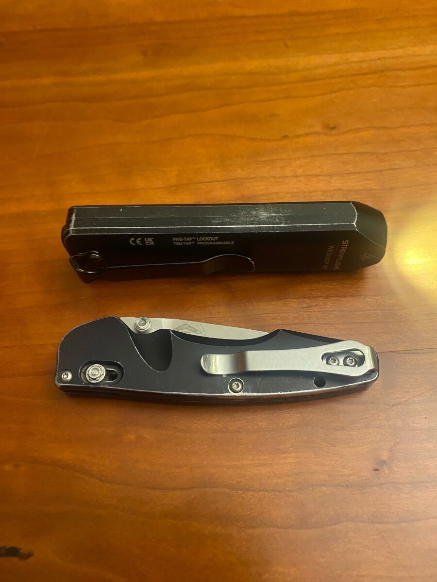
Very Nice! My EDC since February is the Streamlight 88812. Roughly the same shape, and they both look like little Storm Shadow missles! 😄 I've also carried a Benchmade 470 Emissary almost every day for around 15 years. Love it! Cheers! Geoff
-
Yea, I love Victron stuff too! If not for my Xantrex inverter, I’d have all Victron stuff including the Cerbo with all it’s features to play around with. I just can’t justify replacing the perfectly good stuff I already have. But if I only I knew then what I know now, I’d have never bought the lithium package. It would have been much more fun building my own system. I’m considering the new 50 amp DC-DC charger upgrade too, because of its impressive efficiency. We really taxed the 30 amp charger while running the AC during our recent Joshua Tree boondocking trip, it was sucking a lot of battery juice even with two cooling fans to minimize heat derating. I could'n't watch the Victron App while driving, but the shunt log appeared to indicate that it intermittently dropped out and I believe that the 90’ of #4 wire was a contributing factor. I knew the #4 was a little undersized when I installed it, but I wanted use the smaller Anderson connectors. That was a regretful decision for running the AC, otherwise the charger works great to charge the battery. So I did some wire size calculations for 50 amps . . . and learned conservatism is not your friend for long runs. I used 13 volts as a fair charging value with a general accepted maximum 3% voltage drop. For comparison, I also calculated with Victron’s more conservative values of 12 volts and 2.5% (results in parenthesis.) The lengths are total for both the positive and negative wires: #4 up to 30’ (23’) #2 up to 48’ (37’) #1 up to 60’ (46’) #1/0 up to 76’ (58’) #2/0 up to 96’ (74’) WOW! As you can see, your modified 65’ length calls for size 1/0 wire, and that’s without adding the frame resistance. It’s 2/0 for my 90’ length. The cable size calculations are to safeguard from overheating the wire and to avoid unacceptable voltage drops, the same reason why Oliver disconnects the #10 TV charging circuit for amp hungry lithium systems. But as you pointed out, the charger output can be derated 😂 I agree with @Ronbrink thats its better to run all copper rather than using the frame because it’s a known resistance, and a more reliable connection with less termination losses. If you go with larger cable then it’s a wash as far as resistance goes and an extra 18’ would not be a significant cost increase. But I feel the pain if upsizing the wire, it would more than double the already steep cost. Tough call if trying to save money! I think the Aussies use #4 sized terminals because the majority of Victron chargers are being used in smaller European RV’s, Explorer Vans, and Boats with much shorter cable runs. Our longer rigs are probably the exception and a small part of their sales. If they used larger terminals, then more customers would be scratching their heads wondering why! Snipping strands or necking down to smaller wire at the termination point is a common and accepted practice when using larger wire to limit voltage drop in long runs, and it does not reduce the ampacity rating. More food for thought! Cheers! Geoff
-
Replacing black water release valve
Snackchaser replied to Imelda's topic in Mechanical & Technical Tips
Yup, I have to tip up the front too. I was wondering if anyone's tried that product that can be added to the tanks to lubricate the dump valves? Seems rather gimmicky to me. -
Geez, I’m jealous! If for not having to upsize the cable, I’d probably ditch my 30 amp for the 50 too! Good on you for getting your total length down to 60’. My ground is connected to the battery and I was closer to 90’ total with the 2500 RAM extended cab. Have you done a wire size calculation for 50 amps at 60 feet? #4 AWG is small for such length. You got me thinking about using the truck frame for a ground, because logically it should be included in the wire size calculation. It begs the question: What is the frame resistance? I couldn’t help myself, I had to try and figure it out. . . in the wet cold dark. Without an ohm meter that can measure such low frame resistance, I measured the voltage drop across an 88 ohm relay coil instead. First measurement was through the relay and a jumper cable. The second measurement included a loop from the jumper cable back through the truck frame. After subtracting the jumper cable voltage drop, the frame resistance was calculated at 0.00295 ohms. Given the resistance of #4 AWG is 0.000242 ohms per foot, the frame is equivalent to 12’ of #4 cable. Of course there are many margins for error, but I think it’s a fair approximation. So it’s okay to use the frame as a ground, but it's prudent to add the frame resistance to your 60’ length when calculating wire size. BTW, who is your supplier for the TEMCo wire if you don’t mind? I used BatteryCablesUSA in the past, specifically their jumper cable which I noticed Oliver used for the solar panel. It was comparatively inexpensive a year ago, and has doubled since. I hope this helps you out. Cheers! Geoff
-
Mysteries of mooching a hookup from residential system
Snackchaser replied to Cameron's topic in General Discussion
I’ll throw another theory into the pot: This has the hallmarks of a high resistance connection such as loose fitting plug or broken wire. These can change resistance with very little movement or vibration, and resistance means voltage drop. A prime suspect would the 30 amp to 20 amp adapter, since the problem occurs when it’s being used. While looking at your readout, have someone give the adapter connection, and the whole shore power cord, a good shaking to see if that's the cause. Good luck and let us know what you find. Cheers, Geoff -
Inquiring minds want to know! It’s true that inverters are complex devices because they can invert, convert, charge and switch large currents, and they have notable efficiency losses when doing so. However, with the inverter turned OFF, the only “parasite” load I can think of might be the Bluetooth or a memory function. Thats why I conservatively guessed an estimated ballpark value of approximately under 20 milliamps (+/- 20.) 😁 The inverter OFF load was too small to register on my shunt and therefore I consider it inconsequential. . . like years to discharge the battery. But, if I ever disconnect the battery, I'll let you know exactly what the load is and let's not be surprised if it's zero! Also consider this: Even with the inverter “inadvertently” left ON, with no AC devices turned on, the “parasite” load is only 0.2 amps per my shunt as I previously mentioned. That’s because it’s actually operating to power the microwave clock . . . speaking of inefficiency. But that's also a small current that would take months to run down the 390 amp battery. Good discussion! Cheers! Geoff
-
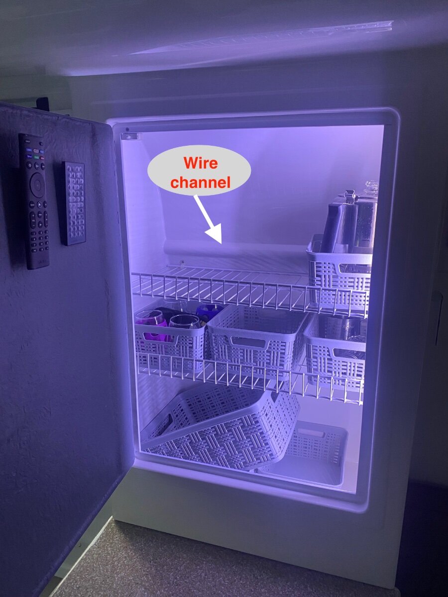
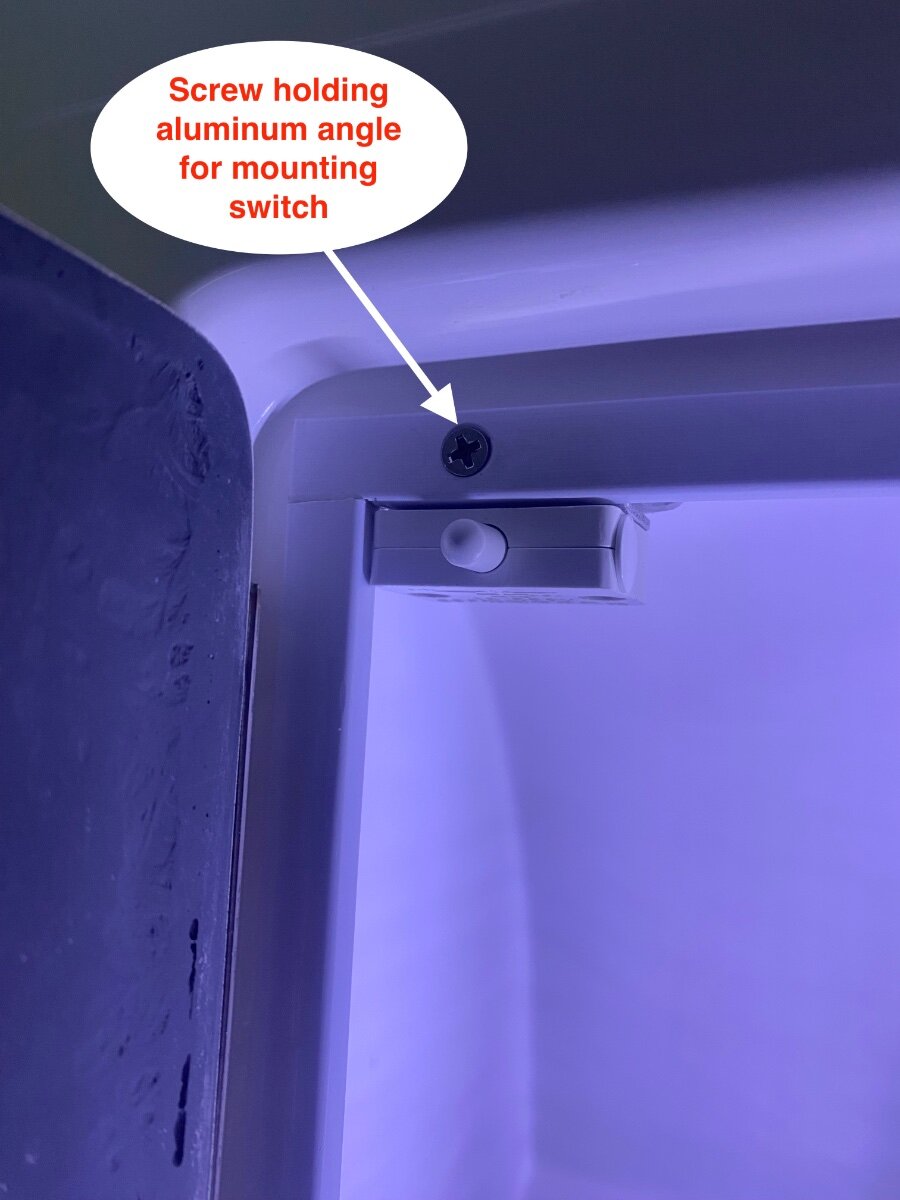
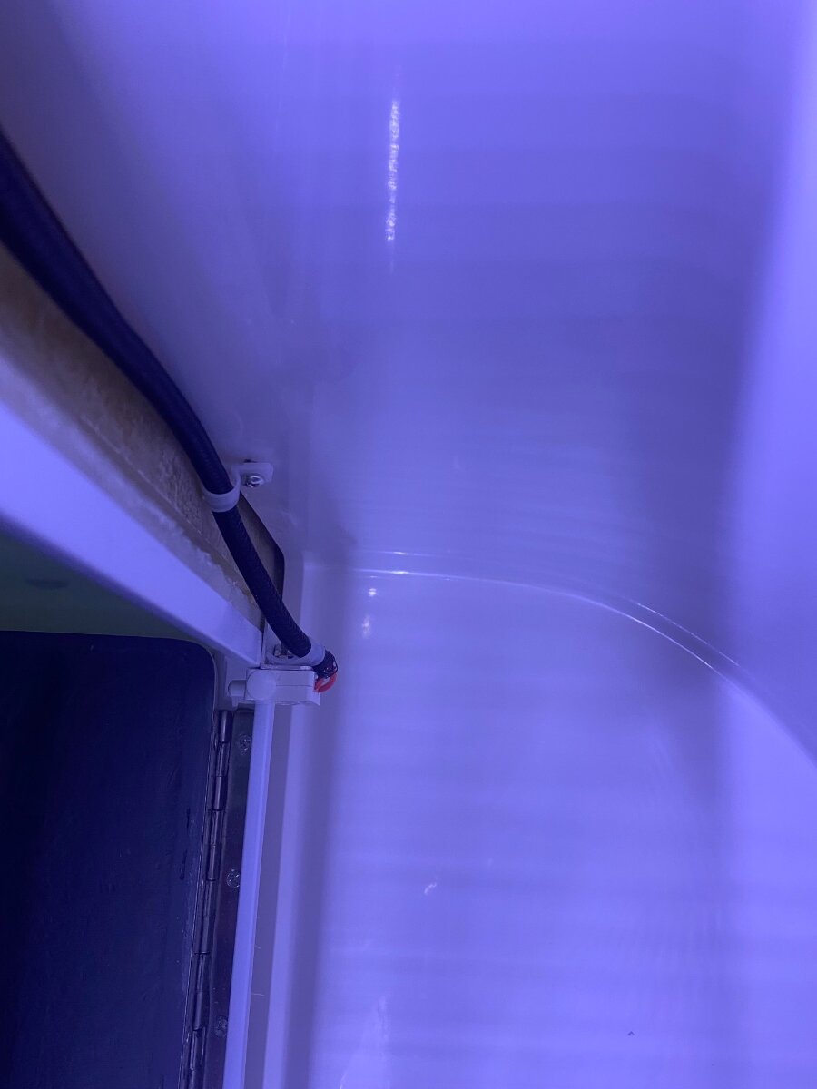
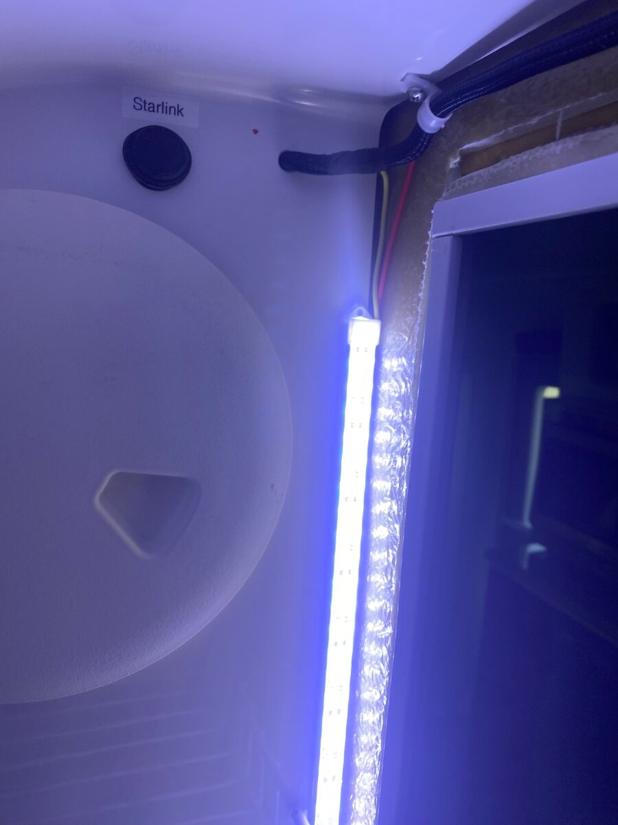
I’ve awoken wifey more than a few times; noisily groping around in the dark looking for a tasty midnight snack. So it occurred to me, why not install automatic pantry lights. . . ones that won’t light up the whole trailer? In a previous post, “Lighting the Abyss automatically,” I similarly installed closet lights that turn on when the door is opened and wifey loved it. So here was a perfect opportunity to use the leftover LEDs and switches from the Amazon 4-packs. This is an easy modification, except that there wasn’t a hot wire in that location. Well actually there is a hot wire for the radio, but I wanted one that’s on the master switch that shuts all the lights off at once. So I’ve done the hard part by figuring out how to get a hot wire from the master switch to the lights. I’m not allowed to make any visible holes or have exposed wiring, so I fished the wires from the rear street-side overhead cabinet - behind the pantry - and into the space behind the radio. There are wire channels in the overhead cabinets under the mats and Oliver conveniently moulded a wire channel in the back of the pantry to join them together. It’s easy to snake a fish-rod through the channel to pull a new hot and ground wire through. I’ve found that a $12 Amazon fiberglass sectional fish rod works great for fishing wires in the Oliver because you can add sections as you push it through. It’s a good idea to pull a string through with the wires incase there’s a need to add more wires in the future. Once the wires are fished though, they can be spliced to the under cabinet touch light. The lights wiring is covered by black duct tape under the mat, and there is enough room to tuck a butt splice in the slot. However, I personally preferred splicing into the lighting circuit in the attic where there is more room. This requires a clamp-on amp probe to find the lighting circuit while turning the lights on and off. Be mindful that the master switch wire is there too and it will also show current, and don’t ask me how I know! 1/2 sheet metal screws work well to attach the LED light bars, or use good double stick tape. There is an air gap between the inside and outside walls of the pantry, and screw holes can be drilled through the inside wall in the same way as Oliver did for the shelf mounts. Just be careful not to drill all the way through the outside layer. I put two LED bars end-to-end on the right side of the pantry where they can’t be seen. A piece of 1” aluminum angle was screwed to the upper left corner to mount the cabinet light switch, and the wires were sheathed and secured with cable clamps behind the door frame. Bon Appetit! Cheers, Geoff
-
Geronimo, if the inverter is disconnected like that, then it wouldn't be drawing any "parasite" losses because that's how it gets its power. However, I can tell you that it’s a negligible value and a non-issue if it's turned off. It doesn't even register a value on the shunt because it's below the margin of error. My guess would be something less than 20 milliamps, which is a general stand-by current value for electronic devices. Although it’s true that old and new inverters are not efficient at inverting power, that efficiency should not be confused with stand by current when turned off, and they should always be turned off when not in use. Here are some calculated values for perspective: A 20 milliamp current would take over two years to completely drain the subject 390 amp battery. However, the afore mentioned 481 milliamp fuse panel current could drain it in 30 days. . . or less considering other battery losses and drawdown limits. That's a pretty powerful argument for doing nothing more than switching off the fuse panel breaker. For those still on the fence about installing a battery switch, I think it’s important to understand this perspective in order to make an informed decision of what option is best for them. Hey, thanks again for the kind words and Happy New Years! Geoff