Search the Community
Showing results for 'Generator box'.
-
 I wanted to share with you my recent battery replacement. My Ollie is a 2015 Elite II which originally came with Trojan T-105 AGM batteries in support of my solar system which utilizes the Blue Sky solar package (SB2512iX-HV MPPT controller and IPN-ProRemote). I replaced my Trojan AGM batteries with Bright Way Group Bright Way Group EVGC6 - 6V 220AH Deep Cycle Golf Cart Battery which OTT are currently installing on the Elite II as the AGM option. As part of this process, I contacted Bright Way Group technician in order to obtain the battery specification sheet (attached). I then provided it the Blue Sky Technician (Ryan Gurin, 760-208-2149). Ryan provided me with the settings needed to reprogram my Blue Sky MPPT Controller SB2512iX-HV via the IPN-ProRemote. Ryan is an excellent resource and was very helpful. I ended up talking to him multiple times. In a nutshell, here is what I did: 1. Disconnected the solar panel via the cutoff switch (street side bed) and opened fuses on the bus bars (also street side bed). 2. Removed the old Trojan Batteries (after taking pictures of the wiring configuration). 3. Cleaned all battery wiring connections. 4. Cleaned up the battery box and repainted the battery tray. 5. Inserted the new AGM batteries and made all appropriate connections (maintained the original wiring configuration). 6. Closed the fuses on the bus bars. 7. Reprogrammed the MPPT controller via the IPN-Remote using the new battery settings. (see attached sheet with adjusted settings) 8. Reconnected the solar panel via the cutoff switch. 9. Verified solar system was operating correctly and batteries were charging as appropriate. Additional Notes: 1. If changing to AGM from Wet Cells, you must ensure the equalization dip switch on the MPPT controller is off. You do not want to equalize AGM batteries. The dip switch will override the IPN-ProRemote settings. 2. Bright Way Group batteries have the same dimensions as the Trojan batteries so they fit in the tray (just as tight). 3. Recommend you review the Blue Sky Learning Center video on how to program the IPN-ProRemote. 4. IPN-Remote Programming instructions (attached) – please note I downloaded the menu sheet from the IPN-ProRemote manual and annotated the needed updates. I found it easier to utilize this menu sheet in order to understand where I was in the programming process (most parameters do not change). As you review, please note you should “restore default settings” first from the set-up menu. I have highlighted in yellow the menu options that you will need to perform an action on. The new settings are also highlighted in yellow next to the appropriate menu box. Hope this helps anyone considering replacing their AGM batteries. 1492893628_BlueSkyIPN-ProRemoteRe-programming.pdf BWG_Spec_Sheet_BW EVGC-220A-AM Final.pdf
 -
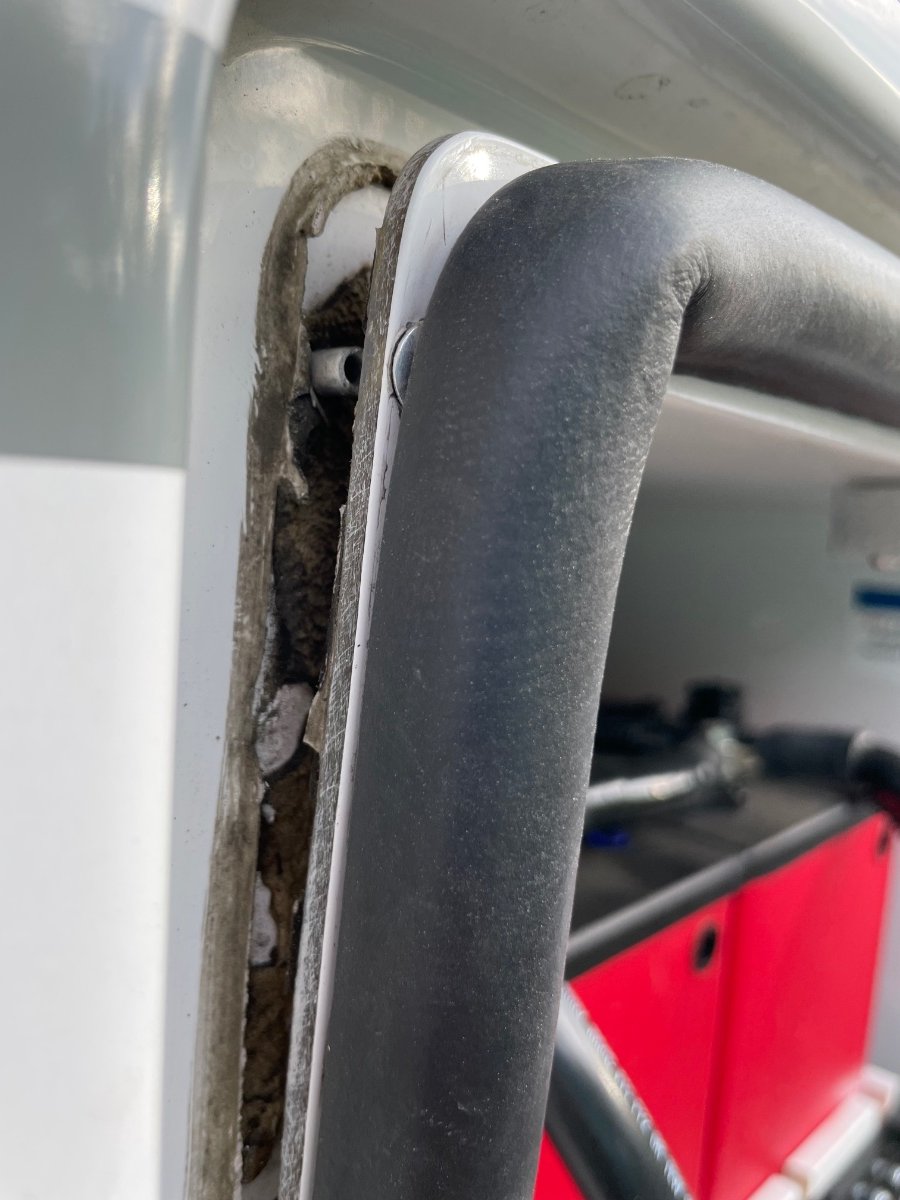
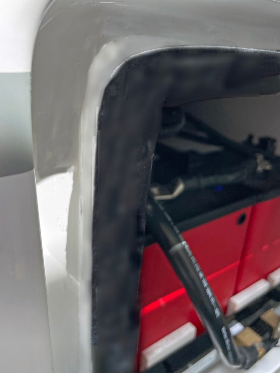
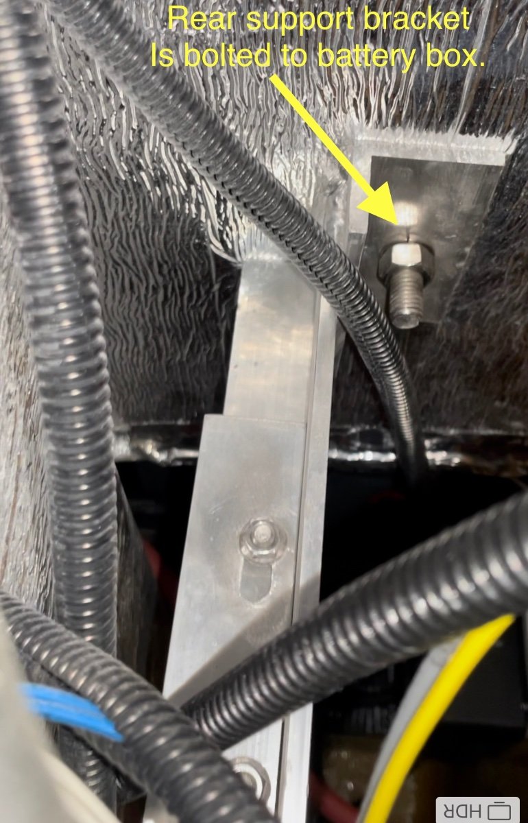
This spring as we were prepping for a new road trip, I noticed the battery box door seemed to be sticking out further than normal. I thought I would adjust the latch to pull the door in a bit tighter. What I found was that the battery box had started to tip forward away from the main hull as shown the pix below. All the rivets up both sides and all across the top of the box had sheared and the box was tipped out about 1/2". I contacted Oliver Support to understand how the box was designed, mounted etc. They cleared me for travel after having me check the support strut inside the trailer (under the pantry area) . After some further consultation I was able to perform a repair. Here's a sketch of how the battery box is installed in our Hull 505 (2019 Elite II) trailer. The repair steps I took following Oliver instructions were: 1) Remove the batteries from the slide tray to get weight off the box. 2) Drill out all sheared rivets. (3/16" bit) 3) Release the 2 support bracket bolts inside the trailer under the pantry (one of which is adjustable). (This step is a pain and requires some long extensions for the ratchet wrench to make reaching nuts possible.) 4) Tip box back into position. (Check that the box base still has a slight outward tip for water drainage.) 5) Re-tighten support bolts. 6) Re-rivet all around the perimeter. 7) Clean seams and add a bead of boat life white sealant around the battery box seam. (See pix below). Repaired Box Above: Door closes with a good seal all around and the box sealed to the body. We are going to keep an eye on this as we travel this next year, and make a trip to the Oliver factory for them to inspect and repair if necessary. I'm not sure of the root cause or mechanism by which the box tipped out in the first place. One concern would be that the box is putting too much pressure on the outer hull while bouncing down the highway. I don't see any indications of cracking in the glass hull or box at this point. Hope this helps if anyone else see's an issue. Craig Hull 505

- 21 replies
-
- 14
-

-

-
 Posted on Facebook also. We don't pick our EII until the end of June. I selected the Lithium Pro package. Truth be told, I'm second guessing that choice. I realize I have 3-4 months to change to the Solar Pro Package. Obviously $4,300 difference is a lot of money that can be used elsewhere. My wife and I come from a truck camper background. When we started the roof top solar package was a 100w Zamp panel on the roof and 2-AGM 12-volt batteries. We had a Dometic 80L compressor fridge. Between the solar and driving to charge the camper batteries, we got by. 50% of our camping was off grid, batteries running fridge, furnace, lights and CPAP Machine. The last 2 years we upgraded to 2-100 Zamp panels on the roof, a new Zamp controller, and new 12v AGM batteries. We also added a Honda 2200i generator. With the Oliver, we see our camping style changing with less back country, but numerous places without shore power ( National Parks, USFS, BLM). When we drove 6-8 hours between campgrounds, our batteries were fully charged. Yet others with the same batteries and solar, and a 3-way fridge ran their batteries down when set on 12v. I can't figure that one out. I wouldn't want to drive with the propane on. I don't think I would have an issue with the lithium package running on 12v while driving. The A/C, microwave, and TV would require the inverter. Are 4-6v AGM batteries with the 340w solar going to be enough? Will I have problems driving with the fridge on 12v? I guess there is another side to this. I'm asking myself if the Lithium and 3,000w inverter are way over my head. I have been reading the forum and some issues have popped up between the lithium batteries and the inverter. Sorry for the lengthy post. I want to get this right, and if I'm good with just the solar package, that $4,300 will be a big help elsewhere. Thanks for your input.
 -
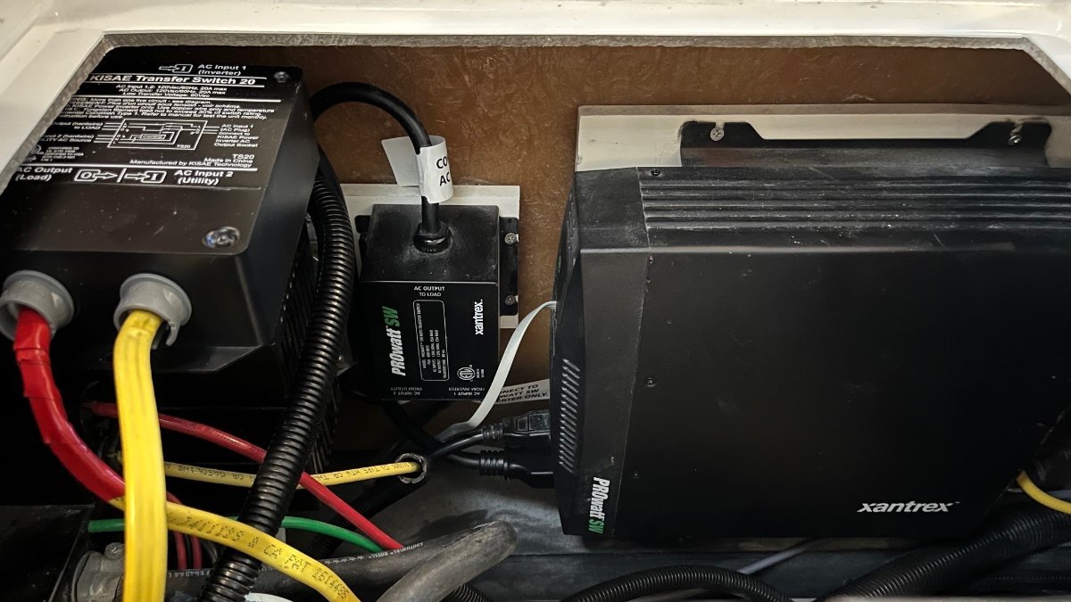
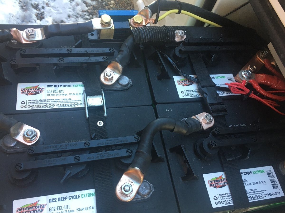
 I see now in the pix that your trailer doesn't have solar on the roof. Sorry I forgot to look closely. Yes...you'll be good to go with new batteries that are being charged with 45A when plugged into shore power as a first step. Future: Rewiring for new Xantrex 3000 to run your A/C When you upgrade in the future to a Xantrex 3000 Inverter/Charger that you'll also likely be wanting to have some of the wiring swapped around to enable you to run the Air Conditioner off of the inverter and battery. In older units (Pre 2021) the Xantrex 2000W Inverter only unit, the AC inverter outputs are routed only to the Outlets of the trailer plus the Microwave outlet. The older units inverter is not wired to a breaker to feed the Air Conditioner circuit. In the day of AGM's it wasn't really a viable option to run AC off the inverter. Those wiring swaps will happen on installation of your new Inverter/Charger, and most changes happen on the back side of the PD4000 breaker box under the dinette. You'll also be needing to find a location for the new Xantrex 3000 display panel once the new Inv/Charger is in place. For future reference, here's a picture of the area under the street side bed where our Old Xantrex inverter was and the new Inverter/Charger was placed. It's the exact location of our hulls original Xantrex 2000 Inverter. We had to remove the old inverter and install a new carrier board for the new - larger size inverter. I could have gone with an Xantrex 3000 but did my design as a drop in replacement as opposed to a full upgrade for running the A/C off battery. Battery Box: You may or may not need to take out the battery tray. It depends on the height/size of the new batteries. In our upgrade we put in 2 - 315AH Lithionics and they fit in the tray with some spacers to take up extra space. Other folks that have upgraded to the larger form factor >400AH batteries have needed to remove the tray because the new batteries wouldn't fit the tray. Final Cable Cleanup: At the time that you do the upgrade of the Xantrex, you may want to consider cleaning up all the various wires that come into the battery box. This is what our 4 AGM cabling looked like at the factory. After cleaning up and adding buss bars you'll only have big battery connection cables left in the box. THIS is completely optional and not necessary but clearing out clutter makes troubleshooting on the road much easier. To clean up the mess of cables you would have all the grounds run to a single buss bar (under the street side bed) and then just one ground cable to the battery box. Likewise for the + 12V cables (red) that run out to the battery box. Good luck on your journey to Lithium. CS
-
 We stopped using a generator after we sold our Class-C. As you know, we have the Victron Multiplus II 12/3000/120-50. The numbers translate to 12VDC output / 3000 KVA inverter capacity / 120A max charge output / 50A max AC input (shore power/generator). I've had our charge output on the MP2 set to 50A ever since we installed ours last summer, and in our case we do not have a reason for faster charging. Specs for the 300AH Epoch Essentials show "recommended charge current" at 50A. Max charge current is 200A, so they could certainly take every bit of the 120A, but why is 50A recommended? Perhaps the lower charge is better for the life of the batteries. With 600AH we can go for days, a week or more off grid, assuming no use of A/C. Given the SW skies cloud up for awhile (rarely except when caused by chem-trails🙁), we can eventually get low on SOC. Under 50% is rare, but I do remember one trip it got down to 20% and the red warning light was on the Victron Connect app! (I set this to 20%.) What we did that time, and would do again whenever needed, is merely to stay one night somewhere with electric hook-ups. Plug into shore power and the MP2 is giving a full 50A to the batteries. At 20% SOC, down 80% on 600AH is 480AH to charge. Let's round up to 500AH (worse-case scenario). To re-coop this would take 10 hours to charge at a 50AH rate. We are going to check-in late afternoon say about 4PM, and even if you're the type to leave before the sun rises (not us!), you're going to be connected for 12-14 hours minimum. SOC is back to 100% HOURS before we would leave and we're good for another week. I much prefer this to carrying a generator and extra fuel. You like to camp summers in the SE, God bless ya, get hook-ups because if you're running your generator all day you will get ugly looks from me and many others! Generators rules at campgrounds are generally no use after 10PM and boondocking in the SE is rare where you could be far enough away from neighbors to run a noisy generator and even worse, the awfully noisy Dometic Penguin II! 🤣
 -
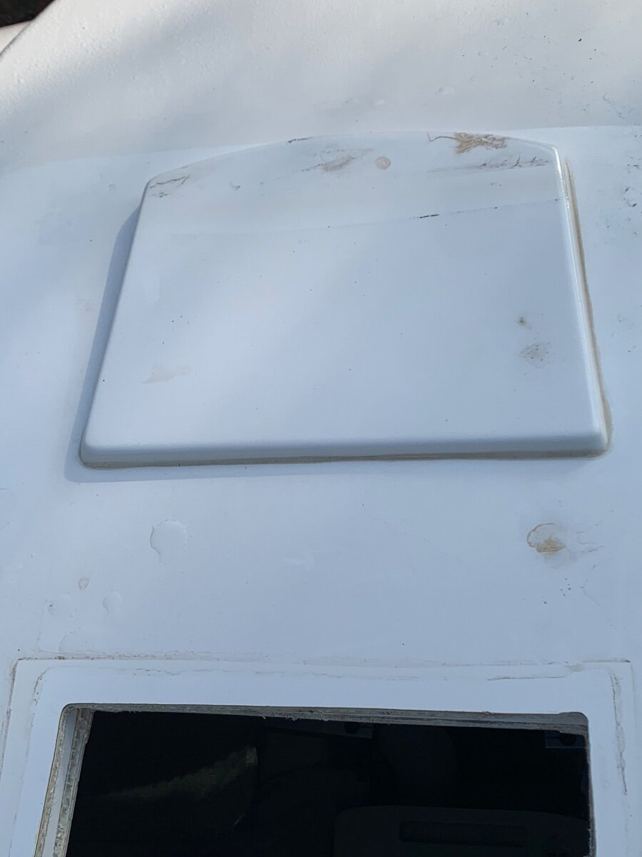
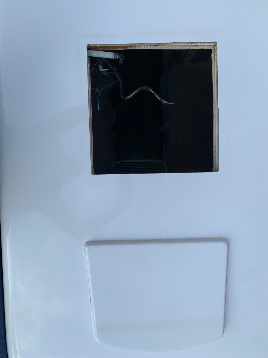
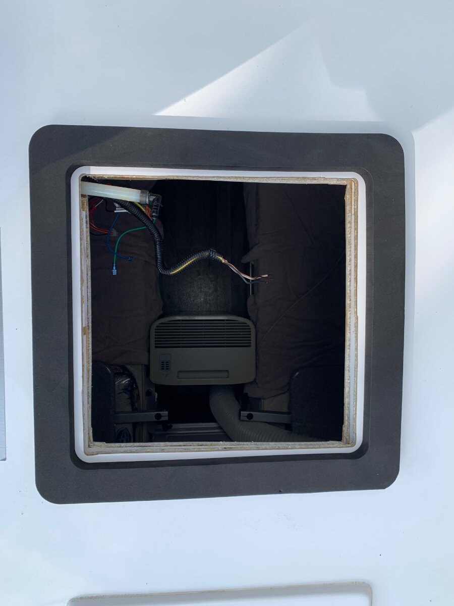
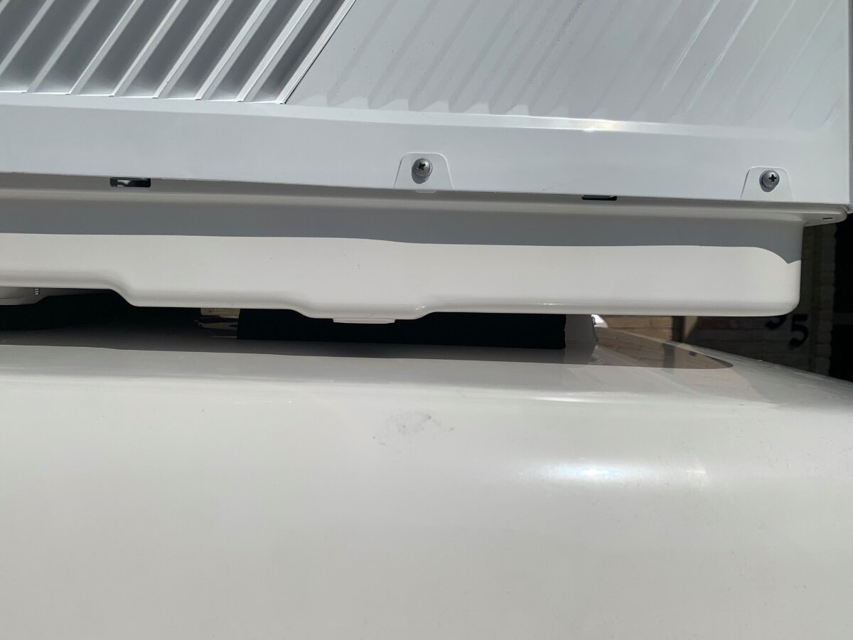
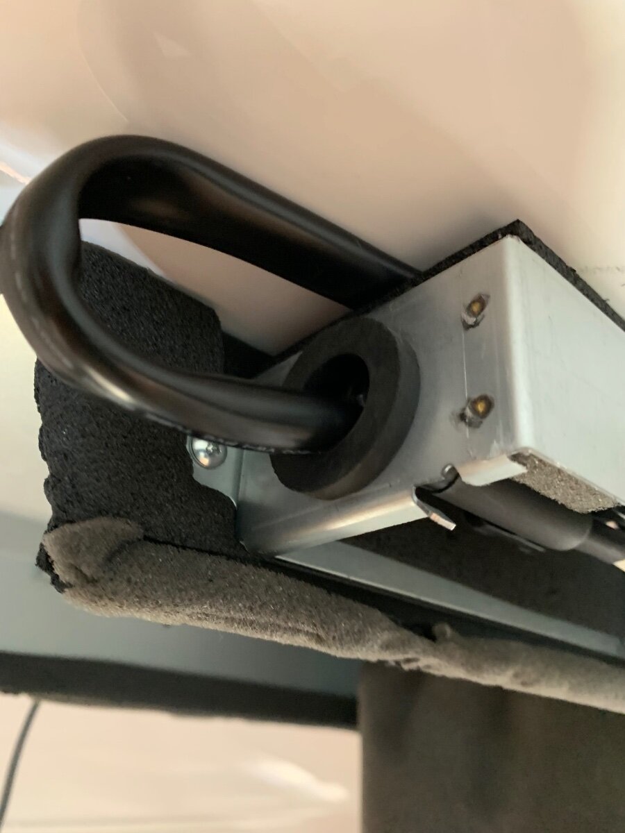
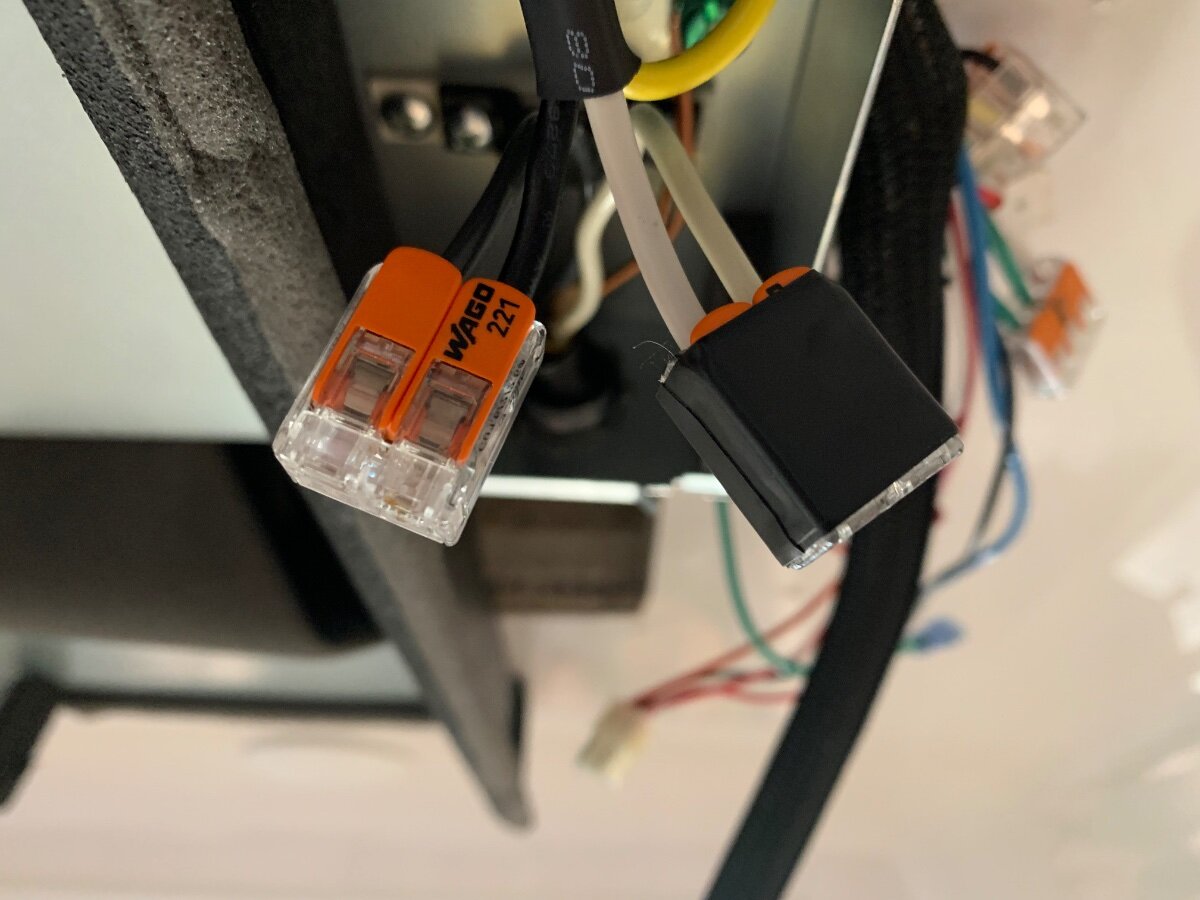
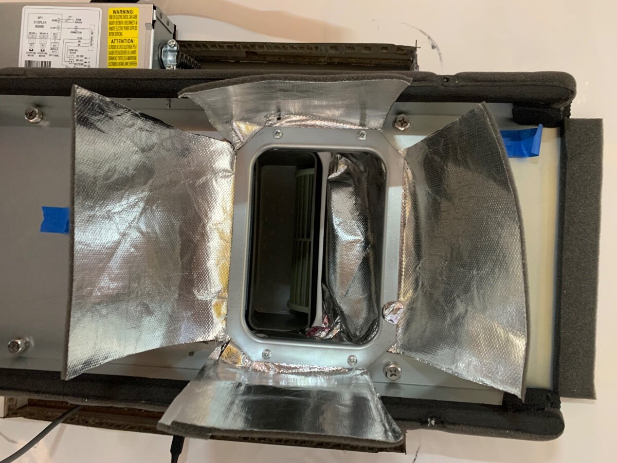
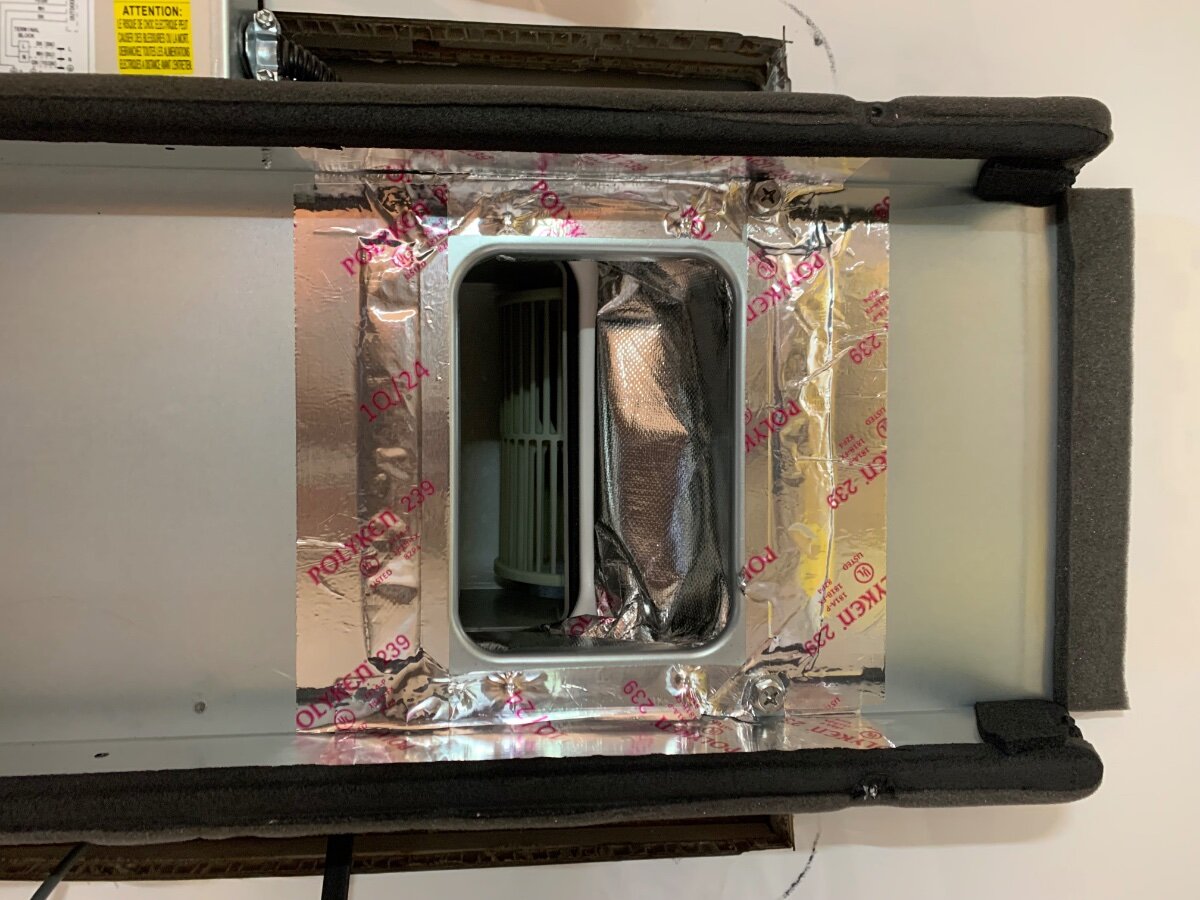
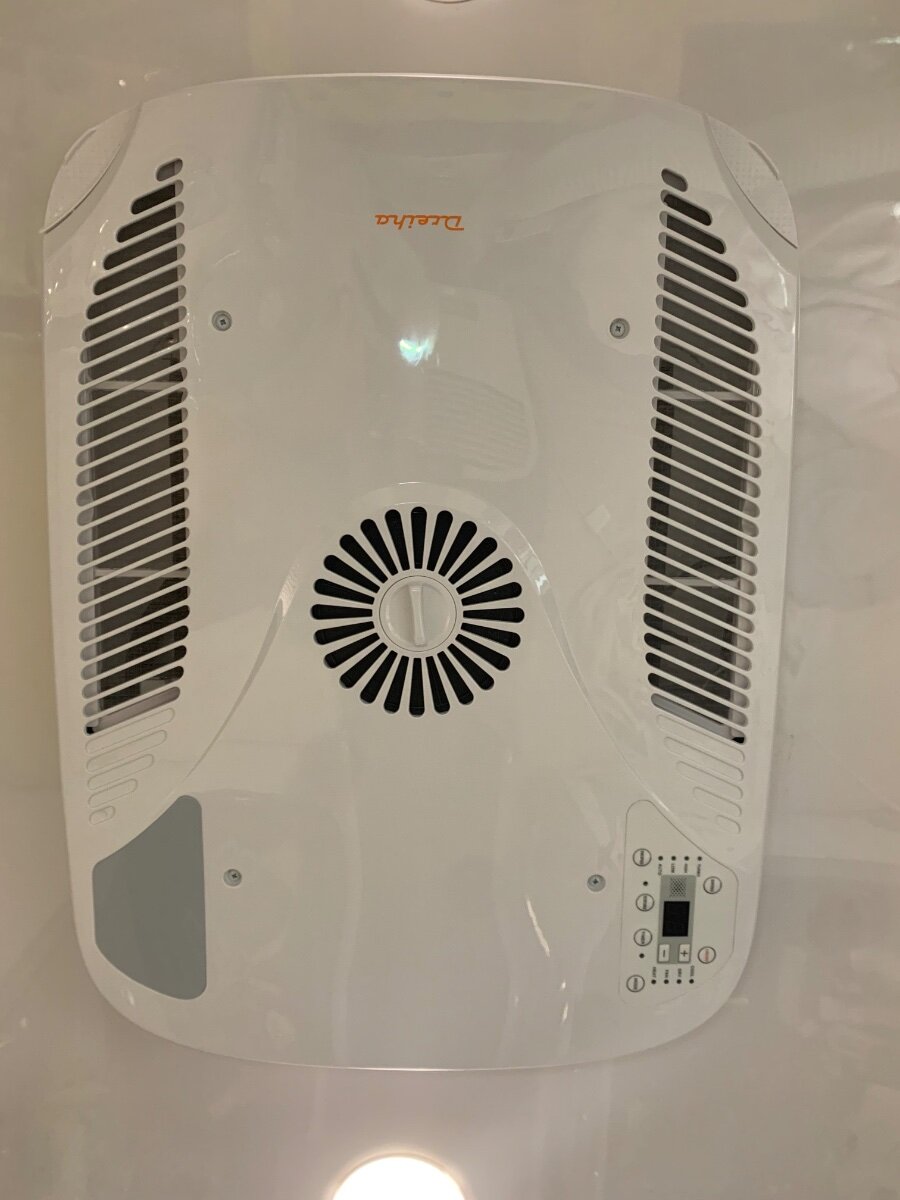
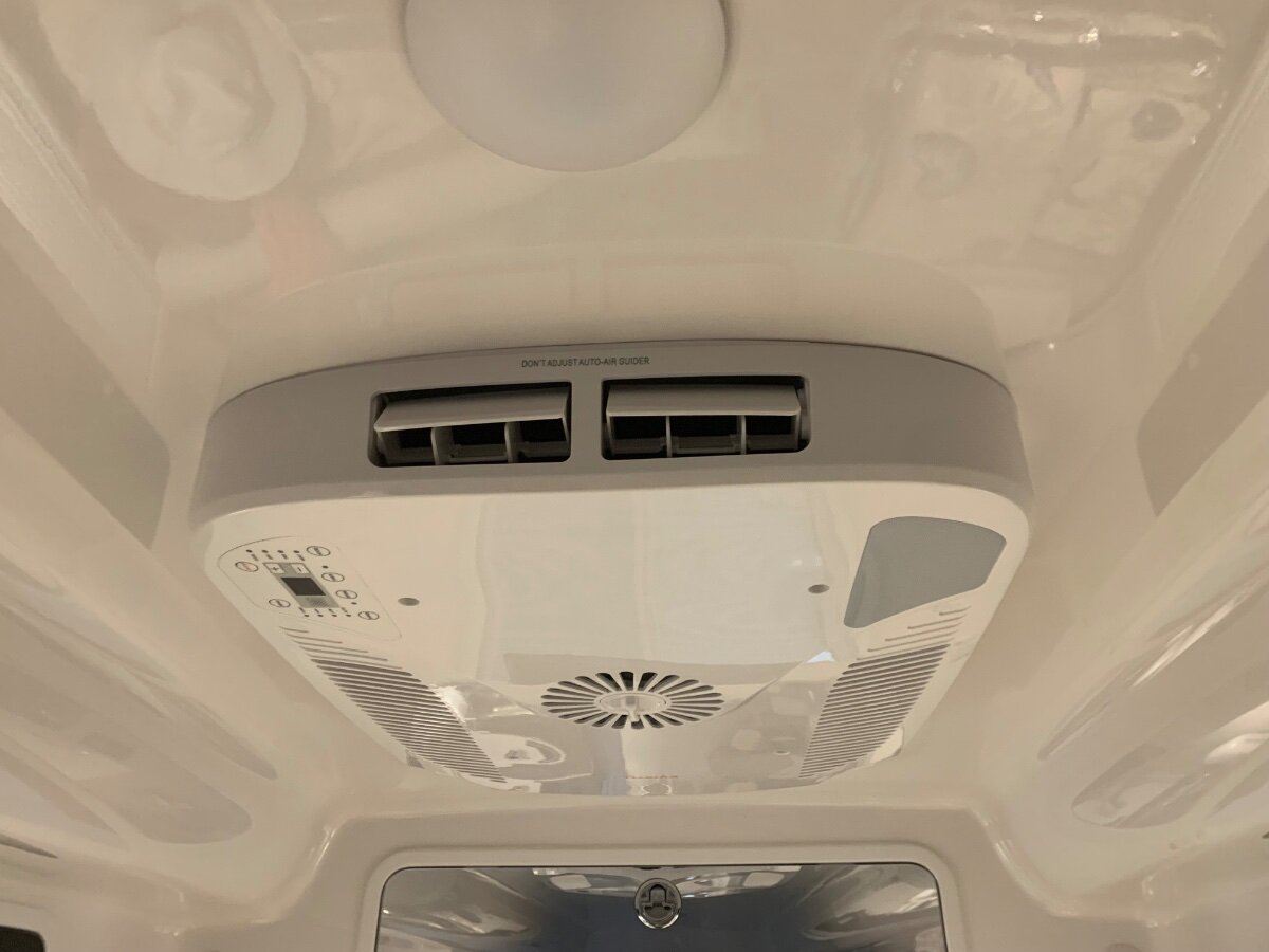
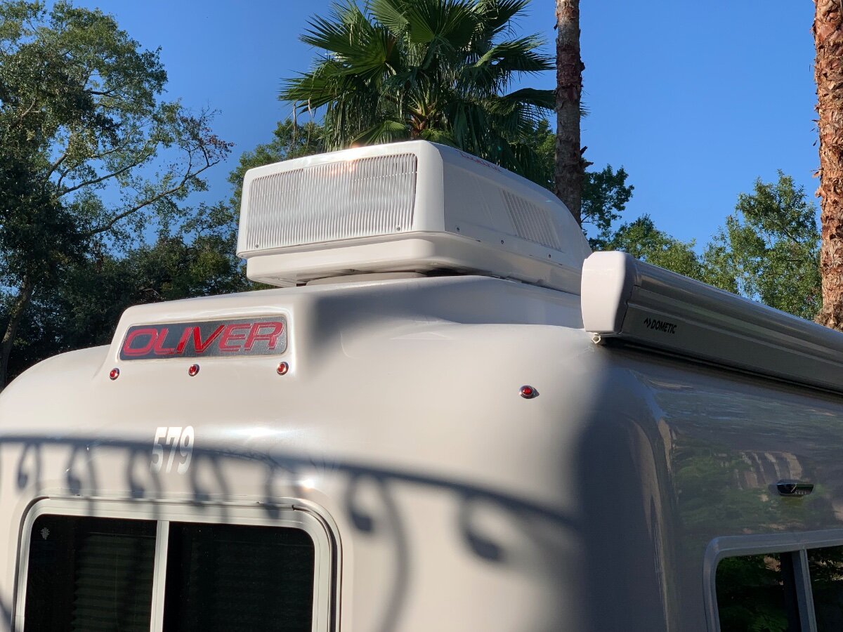
This long awaited swap-mod is now checked off my to-do list! Like many, I tolerated the noisy Dometic Penguin ll long enough; so glad I was finally able to take decisive action with this install. After a couple years of mulling over the various replacement models being marketed, a unit emerged that caught my attention; the newly available Atmos 4.4 seemingly met all of my expectations. I will forego the removal of the Dometic, here is how I proceeded forward: First and foremost, all AC and DC power sources were turned OFF! Scaffolding and equipment/supplies were then staged for Dometic ‘liftoff’ and subsequent Atmos ‘lunar landing’ (only appropriate since I live a couple miles from the NASA Mission Control Center in Houston). Roof area in need of cleaning. Notice the raised fiberglass landing on my year model and that the former condensate drain tube was simply disconnected rather than cutoff. Roof area throughly cleaned and prepped. I decided to adhere the square self-adhesive foam roof seal directly onto the fiberglass and then apply non-leveling Dicor around the cutout perimeter to further ensure the best seal possible. In positioning the foam seal, care was taken to center it as evenly possible, thereby allowing about 1/4-3/8” of exposed fiberglass to lay a bead of the Dicor and finger smooth to finish. Interior view of the Atmos being positioned over the roof cutout. Note the use of the mounting bolts as a guide, as recommended by SDG. Because the ‘rough cut’ edges of the layers of fiberglass (inner and outer hulls, and spacial filler) were inconsistent, I used the foam seal as a reference to accurately center and align the unit; distances measured to each respective bolt. Initially, installation instructions were followed by adhering the supplied straight piece of self-adhesive foam onto the bottom of the unit as a rear support, but it did not make contact with the roof due to relief of the aforementioned fiberglass landing. Alternatively, the foam piece was cut in half and each adhered onto the fiberglass, in like manner as the square seal, along the outer edges of said landing. This adaptation proved very effective in application and purpose, as the last of the next three pics demonstrates. Now that the exterior unit is properly positioned and supported, it’s back inside to further installation. As a side note, I made use of a portable a/c to buffer the heat and humidity of the day! Although my son helped with the heavy lifting and positioning, I cut him loose and completed the remaining tasks solo. Before proceeding, I used foil tape to treat the end of the aforementioned condensate drain tube and secure it to the side. Next the installation of the fabric air plate duct subassembly was started (provided Dreiha Atmos 4.4 Manual details the process). Note I used foil tape on both the upper (at Atmos bottom) and lower (at mounting frame) duct plates, even though most installs viewed applied to the mounting frame plate only. Between the upper and lower duct plate installs, the ceiling assembly mounting frame was bolted in place and hand torqued using a screwdriver only (torque specified in Manual). The AC power connection was very straightforward. The ceiling assembly’s junction box cover was removed, a strain relief fitting installed at one end (the other end had a preinstalled protector) and respective wires routed inside. I reused the Wago Lever-Nuts from the Dometic install, but first tinned the stranded wires of the Atmos lead for optimum assurance in application; electrical tape was used to further secure the Wago connectors. Ground wires were secured per the Manual. The junction box cover was then replaced, DC thermostat wire bundle loom wrapped and tucked away for future use, and ceiling grille fastened in place. . I’m very pleased with this mod, quality of the Atmos and ease of installation! I should mention that SDG preinstalled a SoftStartRV. I will provide an update once the furnace wiring and thermostat mount is completed. A special shoutout to @rideadeuce for forging the way with his install of an Atmos!
- 75 replies
-
- 15
-
-
-

-
Didn't I read @Patriot write something like this? Also, @Ronbrink or @MAX Burner might have commented the same. Who else is still carrying RV technology of yesteryear and rarely to never using it? With 600AH LiFePO4 and 720W solar we're good for emergencies. I get it if you have no solar, but do get solar so you can loose the generator! We also carry 35 gal extra water in the TV for boondocking and emergencies. We can get stuck somewhere for days but TG this had not occurred! Chris loves boondocking, and we much prefer it to campgrounds and truly dislike RV parks (or worse "RV resorts" 🤣). More often than not, when we have hook-ups, we don't use them, and if we need to we charge up, fill water and dump tanks prior to leaving so we're good for another week or so. I preferred adding a 400W solar suitcase vs. a generator, since we live SW, have mostly sunny days and rarely ever need A/C. We have only used the suitcase twice, so it is near the category of the rarely used generator, but no need for fuel and takes less space standing up in the TV. I can have it position the night before so it starts charging before we get up in the morning and it's on all day without bothering neighbors. WE move it to face the sun occasionally but not anal about doing so. Just other ideas to consider...
-
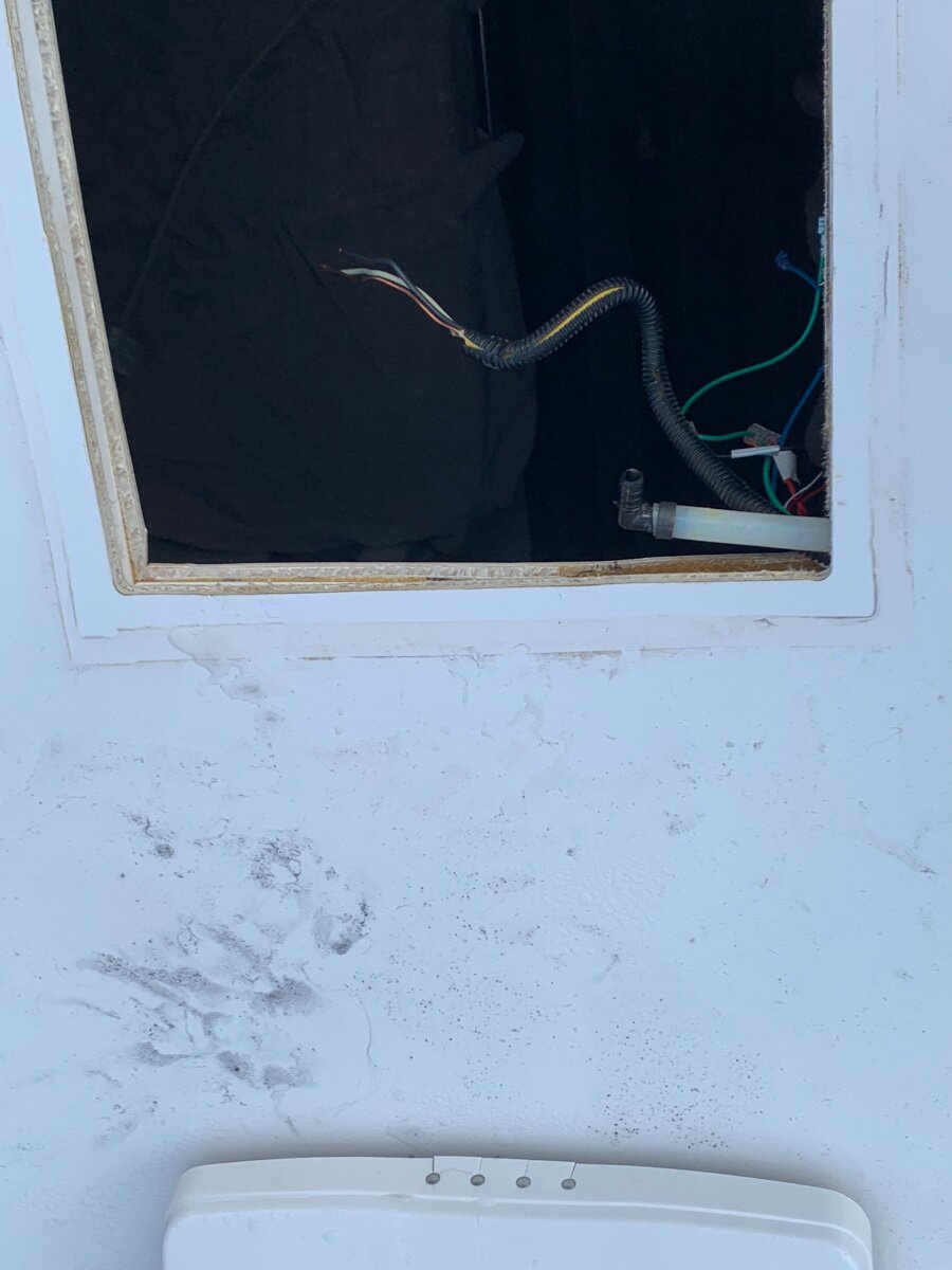
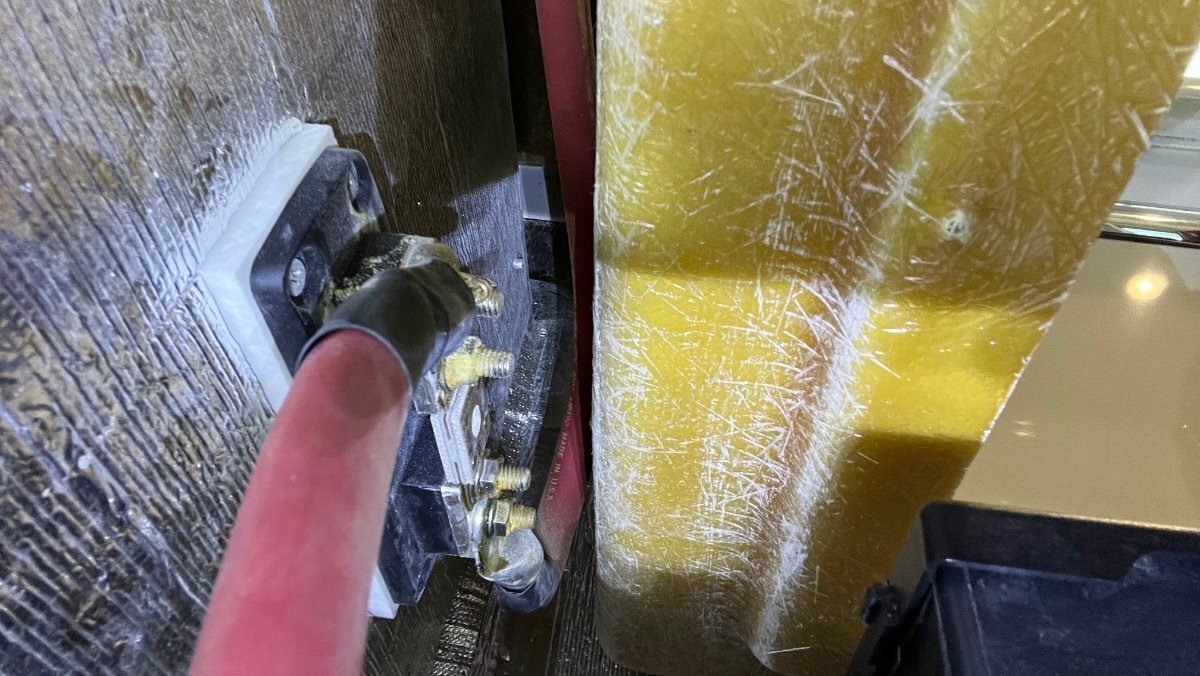
I've searched through the forums here and have seen this topic come up and either fizzle out with no answer/resolution posted or a resolution that I've tried and it has not fixed my problem. I'll start with some background on my situation. I purchased a 2008 Elite back in 2021 and had it for almost 2 years and loved it and never had a problem with it but just wanted more room so I purchased a 2016 Elite II in March of 2023. Ever since I got it I never felt the water pressure in the bathroom (whether on city water or using the fresh water tank with the pump) was that great for the sink and the toilet. It seemed to get worse as time went on and maybe it was my imagination but I felt the kitchen sink and outside faucet didn't have the same amount of pressure anyone. I did find a leak in the back of the outside faucet and just replaced the entire box and that fixed that issue but not the issue in the bathroom. In the basement storage area I found the water pressure regulator and back flow valves and took them out and soaked them in white vinegar for a few hours. This seemed to help the kitchen and outside faucet but not the bathroom. I would recommend everyone do this every couple of years because there was a fair amount of build up on these and they really weren't that hard to get to. So next I took the sprayer off the faucet and soaked the entire handle in white vinegar for a few hours and put it back on and there wasn't any improvement. With the sprayer disconnected from the hose water flowed from the hose ok but not great, but never having seen it flowing from there before under perfect conditions I don't know for sure. I double checked the toilet again and it was still slow to fill. I checked to make sure the valve was fully opened and there were no kinks in water line to it. I did finally notice there is water pressure regulator on the back of the toilet, I don't remember having one on my previous Oliver but I also never had a water problem with it so that night be why I don't remember it. Is/was this standard equipment on a 2016 or is it an addon by one of the previous owners? I have not tried to adjust it yet, not even sure it is adjustable hoping someone here can tell me. (excuse the mess, I didn't realize until just now how dirty the floor behind the toilet is) Next I tried filling the fresh water tank and using the water pump to be sure it wasn't just an issue with city water. Below is a video of the kitchen sink running and you can hear the pump running smoothly and then cut off when I turn the water off then it switches to the bathroom sink and you can see the water pulsing and hear the water pump surging, That pulsing/surging doesn't seem normal to me but I have no frame of reference, I'm hoping someone can tell if that's normal or not. OCVideo.732576672.863039.mp4 The next things I am planning to try are pulling the cartridge from the faucet and soaking it in white vinegar or just replacing it, and putting on a new faucet head just incase the original one was just too clogged for soaking it to help. Have I missed anything? Any suggestions on what I might try next.
-
I've been amplifying the hi-jack but I imagine @Teaney Hull 292 got what they needed in 2 pages and we're all here for more questions from any and all members! I would not worry about the 104F heat issue unless you plan to exterior mount your inverter in the sun! 🤣 Ours is under the streetside bed. It did get up to 104 during testing August afternoons where we get pretty hot, when sitting in the sun. I installed the dual Beech Lane fan, like the one I installed in the fridge cavity. It pulls air from the streetside basement, all the way from vents I added in the bath, closet, etc. With the fan on 104F drops to about 88F, with A/C on and the interior about 74F. Reason you want the Victron is you can run your A/C on generator with the Victron supplementing extra power from your batteries when the compressor is running and when the compressor shuts off your generator would be back to charging batteries. You likely know this already. Victron calls the feature Power-Assist. Re your other comments, she may learn to like boondocking. We love where we can go where there are paved roads and campgrounds. More opportunities west than east. Oct we plan to park the Oliver on the edge of the North Rim! If at a point where we truly want to run A/C on batteries, after we replace the Dometic with something efficient, a third 300AH could be in our future. Given you have the Honda, I do NOT suggest the suitcase addition. We rarely use ours and wish I had saved the $800+ for the suitcase, the Victron 30A MPPT, cabling, connectors, etc. I would certainly suggest adding 400W or as much as you can get on your rooftop. Our 2x 160W panels are now 10 years old. I wonder how efficient they could be. Given that and the flat mounting we usually only get +10 to 12A net charging rates (winter afternoon sun). The 400W Renogy suitcase will double those numbers, from a combination of newer panels and being angled towards the sun. I'm looking forward to reading about your upgrade when you get to it! 😂
-
I got a lot done this week! 🤣 In introduction, our 2016 Hull #113 has roof-mounted 340W Zamp solar, and had a 2KW Xantrex inverter (only with separate PD4000 converter) and 450AH 6V lead-acid batteries renewed in 2021. Given a recent price reduction and a 10% off sale with free shipping, we were motivated to purchase two Epoch 300AH LiFePO4 batteries for a total of 600AH and it made sense to upgrade to the Victron Multiplus II inverter/charger at the same time. Everything described to follow came to $3200 total investment including all small parts and the costs of many on-hand shop materials. Just two years ago, the cost of the LiFePO4 batteries alone would be nearly double! First, all the old had to be removed. Demolition is always fun first step in a project! I removed the lead-acid batteries (sold them on Craigs in just a few days) and all the cables, the Inverter, the ATS and junction box. It’s crazy how OTT wired shore power to inverter power, using wire nuts in this junction box, real backyard mechanic stuff (correct design would be to use a dual-bus power panel). Everything in these pics has been removed (anybody need a 2kW Xantrex system or spare parts)? The second crazy thing is where they installed the main DC fuse (see pic). No way would I have known it's up there until I removed the cables! To access this fuse, you have to sit low reaching through the rear dinette seat.
-
.thumb.jpg.e34bf01ef7f7d5e99ad31856d45afbeb.jpg) And this can be a deciding factor if you boondock with a generator. Depending on which PD convertor/charger you have you'll be running the generator 2x or longer than you would with a 120 amp Victron to top off your batteries.
And this can be a deciding factor if you boondock with a generator. Depending on which PD convertor/charger you have you'll be running the generator 2x or longer than you would with a 120 amp Victron to top off your batteries. -
First, I would say it would be easy to get help from friends at the rally for replacing batteries. A full inverter mod, the custom work of mounting the very LARGE Victron Multiplus II, stripping our all Xantrex parts (ATS and junction box) and related wiring changes may be a lot to accomplish at a campsite! I ran in and out of my garage/workshop 100 times while doing mine for tools and 4-5 trips to Depot or Lowes for hardware over a two-week period of time. If you study the mod threads, plan really well in purchasing parts, get very ready, have a lot of patience (new friends too), maybe, good luck! 🤣 You want the 12V inverter and do not need the UL-certified model (required by code for home installations only). I went with Inverter Supply for these parts for free shipping and no sales tax (see picture). You NEED the VE.bus to configure the Victron for charger/battery spec settings. There are two models (I purchased the USB-C model and there is also USB, depends on the laptop you would use to setup). You need an Ethernet cable also to connect the VE.bus to the Victron MP2. There are YouTube videos showing the configuration steps. You also posted pictures showing the Progressive Industries ATS (Automatic Transfer Switch) and the display which shows the readout of shore power stats. The ATS switches between the two shore power sources (side outlet and front outlet usually for generator in front basket). This will not change but the power coming out of the ATS, connecting to the 120VAC breaker panel has to be replaced with new 10-3 AWG cables to go to the inverter and back to the breaker panel (buy 15 ft to be safe, I used about 12 ft, it runs from streetside bed basement where our new inverter was installed up to the breaker panel under the rear dinette). The Victron MP2 has dual terminal bolts on both + and - sides. I ran the 4/0 battery cables, from batteries directly to the Victron MP2, removed from the 2KW Xantrex (I had the same older model) and all secondary 6 AWG cables that OTT had on the batteries, I also bolted to the Victron bus vs. out to the batteries. If you get this all done at the rally, that will be a great story! Take pictures and post...
-
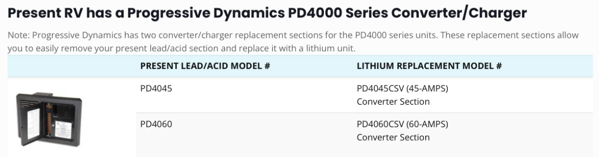
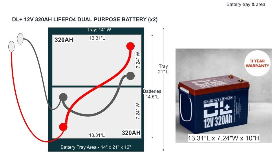
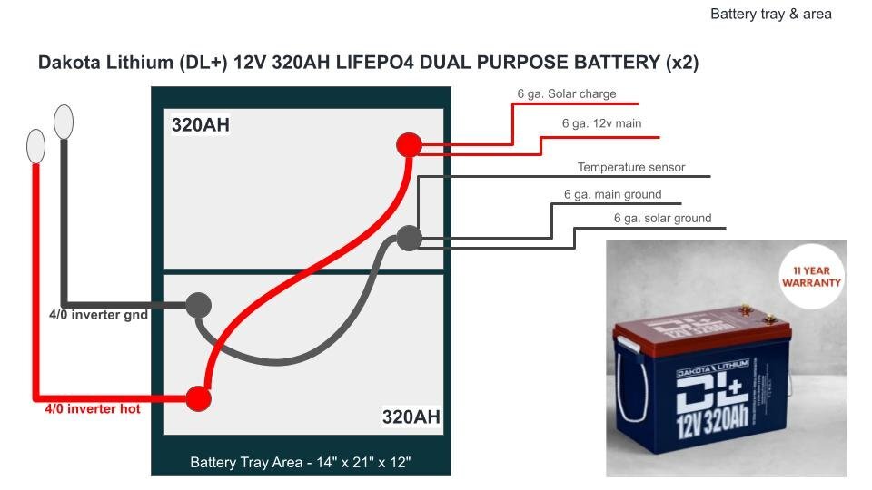
@SeaDawg again, thanks for all the good advice. @topgun2 I'm starting a clean thread on this as not to drive SeaDawg crazier. LOL I was hoping to do a systems upgrade in pieces, if possible. First converter (in the mail), then batteries, etc - if that makes sense. Right now with hull #110 (2016), I have all original equipment, except batteries. Currently Flooded lead-acid. I have the Xantrex 2000W inverter with the BlueSky Solar controller and ProRemote. I did just pick up a new Victron Smartshunt, but holding off installing it until I choose new batteries. I'm an IT guy of 30 years, so not a complete dumb monkey, but maybe a bit slow at first. LOL. I'm always scared to try new things by myself, failing with someone else is not that bad. Also just ordered the new Progressive Industries converter (PD4045CSV) to allow for Lithium charging. Great threads on these forums for all that stuff! I was wondering if the Bluesky Solar controller can be configured to properly charge most Lithiums. I can always call Ryan, if he's still at BlueSky. He showed me how to configure the controller using the ProRemote panel. I'm okay with it. Naturally, I'd love all Victron stuff, if it would fit nicely. And again, I want some hand-holding by a qualified person. Maybe I'll seek out a pro who would allow me to work with them to learn. Some do, especially in the Van community. I'm not yet looking at running the A/C off of batteries. That'll take a newer A/C unit. Not a priority at the moment and keeping it as simple as possible. Realizing I'm just learning and dreaming, and there are MANY paths from which to choose, here's just one idea I was recently considering, due to battery form-factor in the current battery box & tray area. I'm sure there are negatives I'm not thinking about yet. Can I, or should I, do this in stages? Naturally money will be a factor, and I'm a working stiff, so time can be an issue. One thought is to install two 320AH Dakota DL+ batteries to make for a simple and clean wiring setup with redundancy built-in. I was briefly considering a single 320AH battery from Dakota, or any good battery, however, that does not give me any redundancy if one battery fails on a long trip. I'm okay with Battleborns, 12v 100AH, but I'd want very clean connections, maybe a custom bus bar to connect all the batteries with shrink tubing and covers to protect connector bars. At best, I currently only have 160 Ah useable in my old crappy lead-acids. Likely less due to age. Pics are not to scale. I am subject to all the things I have not yet considered, that you will teach me. LOL Thanks!
-
Personally, I won't go anywhere without my little Honda generator. Haven't had to use it yet but it's nice to know it's there in case of emergency. Can run the AC on it for 6-8 hours on just a gallon of gas. Not having solar installed yet is another reason I carry it, so I can top off the batteries in the unlikely event we're ever boondocking (wife hates it 😂). Also, I get that lower charge amps might extend battery life, but in your setup you're only charging each battery at 25 amps, not 50. To get to the recommended 50amps you'll have to set your charger to 100.
-
 Derek, that is a very kind offer. Odds are, I’m going to get the suggested 2 230Ah Li Time Bluetooth batteries. In process of upgrading the Board for the Power Converter, the thing I call the Fuse Box, with part PD4045CSV to charge the batteries, or upgrade to the Xantrex 3000 with the built in Charger. It also charges at a higher amp. I’ll keep you posted as we get closer. I’ll be at site F27. FYI, I put the pictures of all the things in the storage areas. Not sure where it ended up in this forum.
 -
The Ramcharger appears to be a series hybrid which means that the onboard gas generator provides electricity to the batteries to drive the wheels when the drive battery charge goes below the predetermined lower threshold and stops discharging. This feature is great when you deplete your battery and then the generator kicks on to provide electricity. From what I understand the generator can only provide a diminished, set amount of electric to run the drivetrain. This is all fine for driving on flat land at moderate speed and not towing. But what about when you are towing up a significant incline and the battery has gone below its lower limit and the electricity output from the onboard generator is not enough to meet the heavy power demands of towing uphill? It appears the Ram engineers have thought of this and included a “Tow” mode which reserves a preset amount of battery reserve to be engaged along with the generator output in high demand situations. Good thinking. This is very similar to the “Mountain”mode in my Chevrolet Volt (which reserves electric for climbing when using the onboard gas generator. But, what if someone forgets to engage towing mode and depletes their battery before starting to climb a long steep grade while towing? If the Ramcharger behaves like my Volt in similar conditions, you can quickly reach a point where energy demand outpaces the capability of the onboard gas generator, forcing the vehicle into reduced propulsion mode. I know with my volt the accelerator response and power is greatly diminished, placing the car into a sort of enhanced limp mode. Will the Ramcharger do the same? Will the reduced propulsion mode on the Ram be enough energy to tow a heavy trailer up a grade slowly or at all? Will the tow vehicle come to a stop leaving you stranded on incline? Who will be first to test this out and report back? my point above is stated perhaps more clearly in this article, however it is still not clear whether the enhanced battery reserve is available in standard drive mode or only when the driver manually engages tow mode before heading out with a fully charged battery. https://insideevs.com/news/751670/ramcharger-battery-size-usa-towing/
-
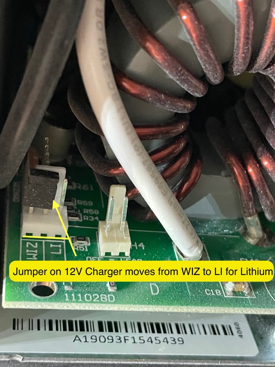
Imelda: For unit 642 (maybe a 2020 or 2021 model year) first step is determined if your Xantrex is an INVERTER only function or if it's a combo inverter charger. If your system has a 2000w xantrex inverter/charger then the battery swap is simple. If not, then you'll currently be using an progressive dynamics charger which is located in the black breaker box (under the dinette seat). The pix below is the breaker box with the cover removed. The 12v Charger is in the upper left with the white wire connected to the charging board. Some folks with the Progressive Dynamics charger see a jumper switch on the charger unit (upper left in overview) for charging lithium. In the pix below I've zoomed in on the charging board jumpers. The issue with that LI setting is it's not the "best" way to charge lithiums as it's simply a constant 14.6V voltage...not a ramped profile. The WIZ setting of the jumper is a PROFILE for AGM or LEAD Acid. The LI Setting is just 14.6V (no ramp/no profile). Some battery manufacturers (including Lithionics) won't warrant their battery in presence of the constant 14.6V no profile setting. Whichever lithium battery manufacturer you select, LI Time, Epoch, etc....be sure to check what they need as a charging profile. If a constant 14.6V works for them, then you might be able to a drop in maintaining your existing Inverter and existing charging system. I know that battle born did warranty their batteries with the Progressive Dynamics chargers. Also, there are new "Lithium compatible" plug in boards for the progressive dynamics load center that offer a lithium profile wizard. So just upgrading the charging board in your Progressive Dynamics energy center is a possibility. Upgrading requires unscrewing that charging board, disconnecting the white wire and sliding in and securing the new charger for LI. In our case (2019 model hull 505) we swapped out the Xantrex 2000W Inverter (only) for a newer Xantrex 2000 inverter charger before installing new Lithiums. My full upgrade article is here. This may be too much of an effort for what you want to accomplish but hopefully my explanations help. Craig https://4-ever-hitched.com/ggs-blog/f/lithium-battery-upgrade?blogcategory=Electrical+Upgrades
-
Have use my honda generator to chargé our batteries 2 times nów, today being The second Tim’e, disconnected from generator, went inside to verify they full charges, and no Lightning or Power to anything on The master control at The door. Went inside when i initialy starter generator and had Power at than time. My FIRST attempt about a month Ago , same routine and no problem. We had our trailer winterized when we picked it up SO no experience with it SO far other than using generator to keep batteries chargéd. Recommendations when to start looking.
-
Hello. My wife Karen and I are purchasing the 2025 Oliver Legacy Elite1. What generator is being used by other LE1 owners, to run the Truma Aventa Eco air conditioner? I have determine the Predator 3500 will not fit the storage basket on the tongue. So I’m open to suggestions. We drive a GMC Canyon with v6 engine. Thank you so much.
-
Approximately. Here's what AI spit out assuming 400 Ah of batteries at 20% SOC using a 40amp, 60 amp, and 120amp charger to bring batteries back to 100%. Also assuming that the generator could handle at least 1800 watts output steady for the 120 amp charger. 40 Amps: 7.7 to 8.2 hours 60 Amps: 5.3 to 5.8 hours 120 Amps: 2.65 to 2.9 hours
-
We also have a Honda EU2200 in the bed of our F-150. When we need the generator, I remove it from the truck. It sets on the ground outside of our trailer or truck for "Just in Case" bad things that happen. Having it run in your TV or Tongue Box has several problems. One is that up front you have no line of sight to see a fire. At least if you put the generator on the ground and to the street side, if it cooks off, you have a chance of seeing the fire ball directly. Now I have never heard of a Honda generator "Self-Immolating"..... but if ours does, we will not be exiting the trailer about 4 feet from the fire. With it on the street side we at least could have an opportunity to see the fire ball and exit the trailer on the curb side. I would then grab the cord and disconnect it from the generator. Then use our awning crank as a hook to move the burning generator away from our Ollie. Or it could just sit in a box in the box at the front of Ollie and maybe the auto fire extinguishing system will overcome the leaking gasoline fire. Or if you run it in the TV bed, and it has a "problem", you would have a great excuse to buy a new TV. But then, what are the odds? Maybe something to really think about I suspect. 🙂 Safety John
-
 I believe it's in the engine compartment. We'll soon see. It's pretty unique. If you want to stop and charge, it's a phev. (Plug in hybrid). But, if you want to make tracks, and the distance, the pentastar solely charges the battery. Contractors can use the battety on-site, vs bring in generator. The battery isn't huge. So, daily driver, purely electric. Towing over distance, definitely need the big gasser pentastar to charge the battery. I'd say for now, possibly best of both worlds. Still reliant on fossil fuel for long distance, but at least only one drive train to maintain. The reliable pentastar is pretty much tried and true, though not as an onboard generator. The power of rhe electric motors is impressive. It's a compromise, but, probably a good one in today's world.
 -
This is another GREAT example of me reading this and feeling like a Monkey trying to do calculus. With that said, wonderful info. If it took you doing all this for your changes/upgrade, then, I do not think it makes sense to do it at the rally. I got great advice to look at getting the Lithium replacement Model # PD4045SCV 45 amp for the Progressive Dynamics Power Converter System, what I call the fuse box. It allows the proper Lithium charging. It’s $180.29 on ETrailer. I think, I could be wrong, if I put in the new Lithium Batteries, add this part, I will be ok with my current Xantrex ProWatt SW 2000 for now. Also was told I had to change the solar charger for the 180 Portable Solar Panel I have. Will now research that. Thanks for letting me know if I’m on the right path. I really do appreciate it. I also hope another Ollie Owner who shares my lack of knowledge will get good info from all the great advice others are giving on this thread.
-
 Gary, aH stands for Amperes Hour, the number of amps a battery can provide in one hour. 100aH means the battery can provide 100 amps in one hour. There might be a more technical explanation that some of our techies can provide. We’ve found that our 300aH has been plenty and when we had 200aH for over a year we never had an issue. There is more useable power in a lithium than in an AGM. When we had our 400aH AGMs we got very near our limit while camping in cool cloudy weather at Glacier NP and Grand Teton NP. I had to run the generator because the solar was unable to keep up. Because you can take lithiums down lower than AGMs I don’t think we would have had the same problem. I will add that we don’t use the AC on battery power, run the fridge on propane, and are generally pretty conservative in our electricity use. Occasional microwave and blow dryer are the big loads. Mike
 -
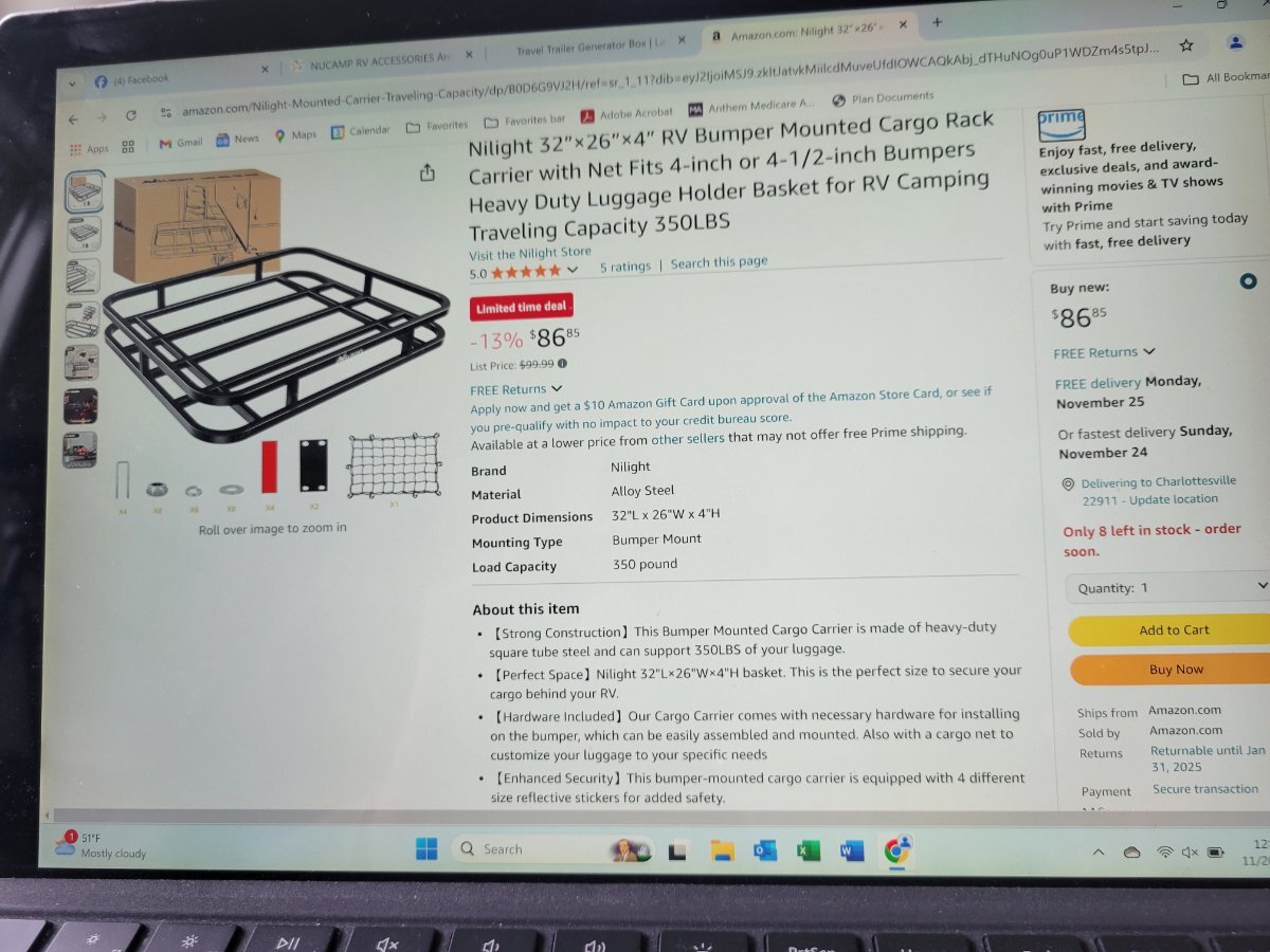
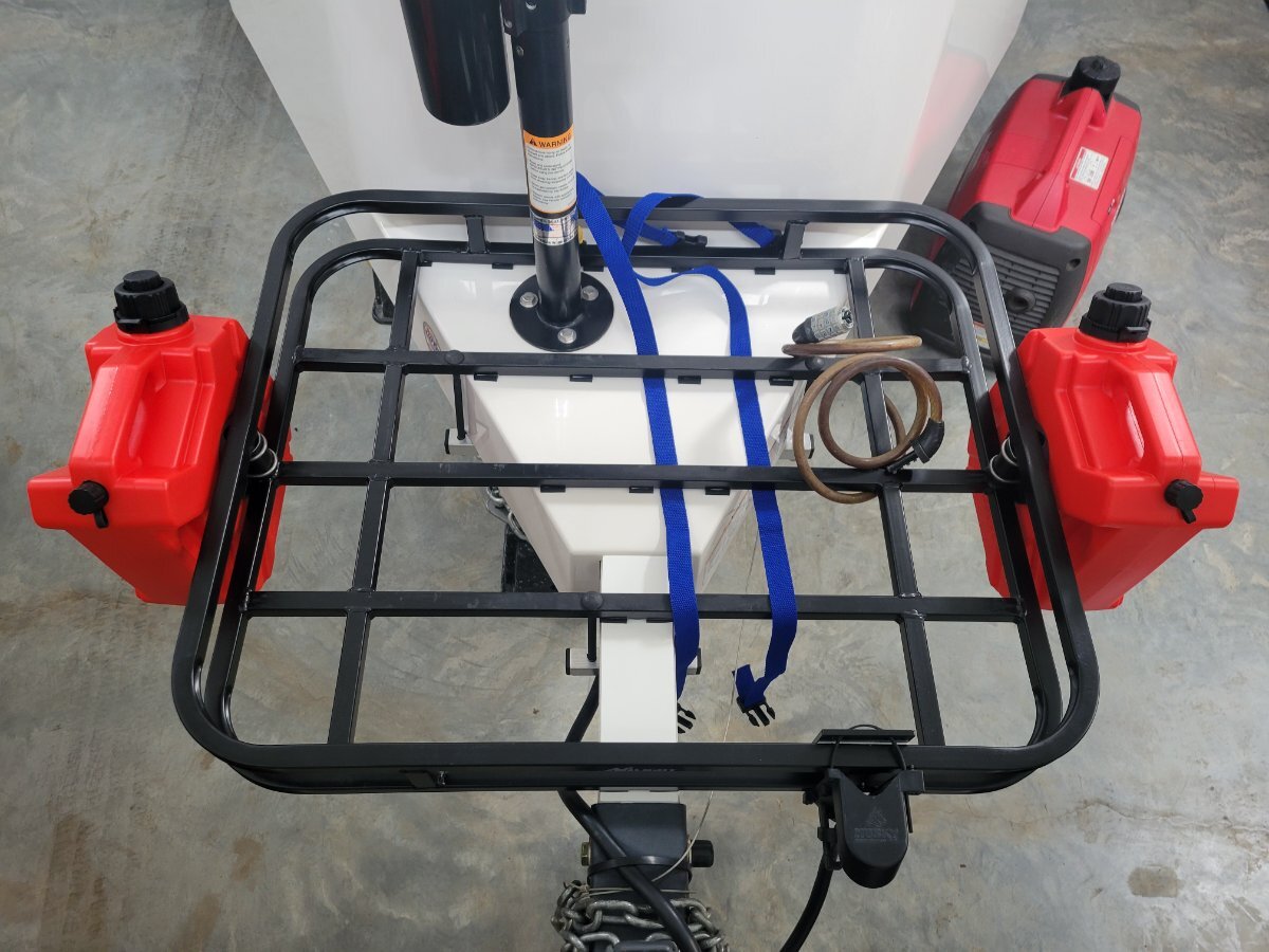
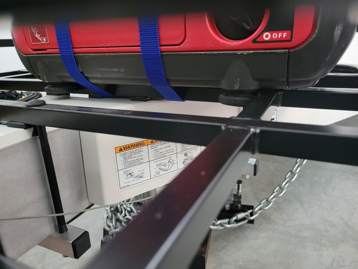
I wanted a front storage basket that my generator could travel in that would also have enough extra space for a couple other items. This basket fits over top of the jack so there is no wasted space behind it, and I didn't have to drill any holes in my LEII to attach it securely! I used two pieces of heavy guage 1" aluminum pipe across the bottom of the tounge and four 8" bolts that are through bolted to the basket on the sides. I used square rubber spacers between the rack and the fiberglass tounge which allows cargo straps to secure items in multiple locations. An added bonus is the basket framing is spaced perfectly to allow the rubber feet on my generator to fit securely over it (I did stick four more rubber spacers to the bottom of the generator where it straddles the basket framing. The basket, the generator, and the other items add about 100lbs to the tounge. I will be offsetting this added weight with a receiver style bike rack I will be adding to the rear of our LEII (more on that in a future post). I measured how tightly I will be able to now turn (especially while backing up), and I should be fine. I am very happy with this storage basket and the price! 😊


.jpg.2563185667c22ee5c68422850ff4bed5.jpg)
.jpg.4c60ff4d9a3404e60fac13bec748c983.jpg)


.jpeg.4632db6af0b004f82ea58c8212cf4f5e.jpeg)