DavePhelps
-
Posts
395 -
Joined
-
Last visited
-
Days Won
20
Everything posted by DavePhelps
-

Slow Fresh Water Drain; Dewinterizing
DavePhelps replied to Gliddenwoods's topic in Mechanical & Technical Tips
The FWT drain is at best slow draining given the design constraints of the system. One issue that can make it much worse is when bits of plastic end up inside the tank from drilling the various holes and not meticulously cleaning it out before installing. I have had these bits bunch up at the tank outlet and at the drain valve. When I added my new water supply draw tube, I cleaned and vacuumed out the tank best I could, and cleaned out the drain valve while I was in there as well. Now, not really wanting to go through that all over again, if it seems plugged up, I'll take my air compressor and blow up the outflow tube (30psi is good) into the tank. This usually clears the occlusions long enough to let the tank drain more normally, which is still slower than I'd like. Hope that works for you. Dave -
It is my understanding that propane tanks under 100 pounds have 12 years before they need to be re-certified. So you have until 06/2030! 👍 Dave
-
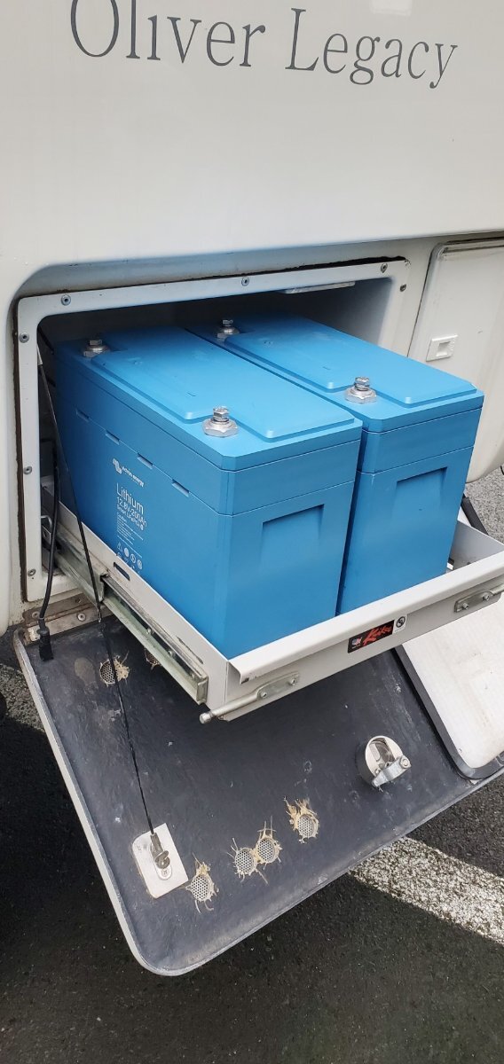
Here's a pic of a couple of "dummy" 200 amp/hr Victrons mocked up in my tray to see if they would fit. Dave

-
Well, plans change! After deciding this whole conversion project was above my pay grade, I spent some time talking with my local solar company reps about my system. I have run out of battery several times with my old AGM's when camping off grid where the sun was rarely seen. Rain and gray here in the PNW, especially in the shoulder seasons. For my current needs, the 400 amp/hr Victron will have more than 3 times the power available to me compared to my old AGM's. Maybe overkill. But looking to the future where I may be getting a compressor fridge (when my 3 way gives up the ghost) then things start to even out. As far as I know, this is the most power one can pack in to the Elite 1 while maintaining the OEM battery box and tray. I also changed my mind and am getting a Victron inverter/charger. Mostly for the better charging compatibility with the Victron batteries. We'll see how this all pans out. The components are expensive but I believe Victron makes a quality product with stellar representation. Pics will be forthcoming when this all gets completed for Elite 1 owners (and anyone else) who may be interested. Cheers, Dave
-
Not sure if there have been changes since my 2015 Elite 1 was built, but it has an hot air supply in the bathroom. Even still, a return air vent under the sink makes very good sense. Dave
-
I would recommend cutting in a small 4" return vent under the TP holder. I think this area would be good with no water intrusion from showering. At least, I have never noticed this area to be wet after I take a shower, ymmv. Not sure of your model or year, there have been changes made. I don't get the closet vent at all. It is a separate space from the under sink area. I would rather have a return vent move air directly from the bathroom into that space, not from the cabin, to the closet, to the under sink area. I had great success adding new return vents in the rear of my trailer (my furnace is under the front dinette seat). I blocked off the OEM vent which was right next to the furnace. I had substantial temp increases between the hulls. I have also wanted to put one in the bathroom as well but got sidetracked with a pile of other projects. It is now on the short list however. Good luck. Dave
-
My battery box tray is the same as your on my 2015 Legacy 1 trailer, 14.25" X 14.25" X 11" I was ready to go with the Epoch battery but pivoted after consulting with a local solar company. I am now getting 2 of the Victron 200 amp/hr batteries. They fit beautifully in my tray, and together will give me 400 amp/hrs of battery power ( well, almost). These batteries have a remote BMS, so the room in the battery where the BMS is normally located can be used for more Lithium cells and/or the batteries can be comparatively smaller with more available energy than other brands. Not cheap by any means. The batteries are expensive and then you also have to purchase the BMS module separately. For me and my needs however, it was worth it. I also elected to have this outfit do the install for me. The whole project just grew way beyond my comfort zone for a DIY job. After seeing their part list for the job, I'm really glad I'm going this way. My hat is off to all you folks who took this on yourself. You saved yourself a pile of money! When completed, I'll post a review with pics. Cheers, Dave
-
Had similar issues with my Legacy1 trailer. Washboarded roads really puts these connections to the test. I had Oliver send me some extra clips which I added in addition to the OEM clips. One or two per shade as I recall. I then used thin nylon washers to shim the clips out so they were all in plane and fully engaged the groove on the back of the frame (use a straightedge). Since then, I have also started towing with all shades in the up position (both sheer and blackout pulled up). This puts the drawbars (?) at the top of the shade frame, placing a little more weight at the top of the frame and not stressing out the clips as much. So far so good. Dave
-
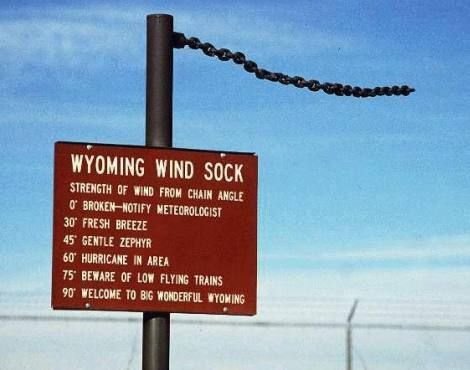
Don't have a Clam shelter, but have been snug as a bug in my little legacy1 in very high winds. I can't imagine any of these shelters are up to the task of the high intensity winds and micro blasts of the inter-mountain West and other areas. Best to take them down at night. Also, there is a pretty good app called Windy that gives detailed wind information, both current and projected, worth looking in to. Dave
-
Thanks for that. Now that I've thought this through, I can see that in this case, ability to vent both in and out would be best. Dave
-
Looking forward to your renovation JD. You could add more solar panels up there if needed. Regarding the vent. I wonder if it could be replaced with an Air Admittance Valve inside the trailer. That would clean the slate up on the roof. My vent goes up through the closet, a great place to put the AAV. Used them a lot in residential plumbing to solve difficult routing issues in old homes. Any plumbers out there to comment? I know Oliver already uses one to vent the kitchen sink, so why not the main stack? Good luck and like your new scaffold! Cheers, Dave
-
I have what rich.dev showed above and has worked great. Otherwise zip ties as Mike and Carole suggested. Twisting chains to adjust length is not recommended and can dramatically reduce their strength. Best to cut them to the required length with no twist! Dave
-
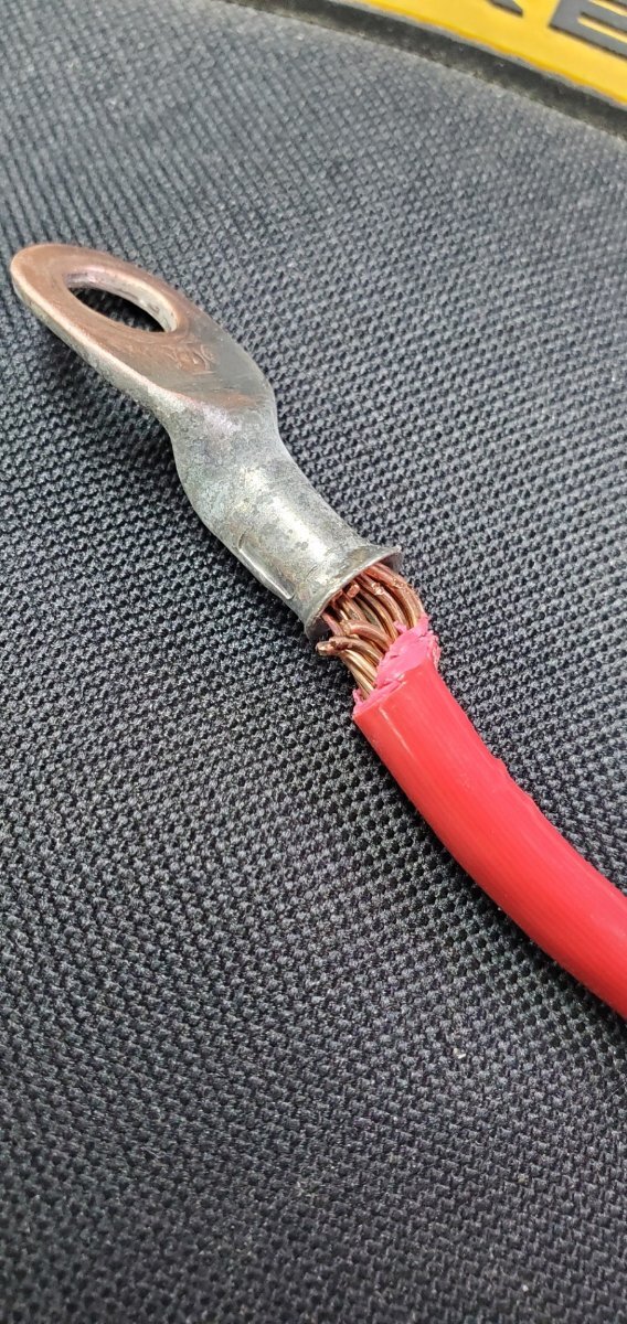
Revitalizing this thread with just a few more questions! Yes, here I am again..... Charger converter is 45A. All new wire will be 4awg. Still considering either the 1, 300amp Epoch or 2, 100amp Battle Borns.... My new block plan including the solar details. 1. Should I replace the OEM 30A breaker between the SCC and the battery with an 30A anl fuse? If I keep the breaker, how would you orient the aux/battery connections? 2. Given these new Lithium batteries have their own EMS, do I no longer need the OEM temp. sensor wire between battery and SCC? It's easy to keep but don't want to create data conflicts. 3. Where to put a battery disconnect switch? Between the battery and the shunt? Assuming the negative lead is the correct one to switch. Is this step even necessary? Any other comments very much appreciated. 🙏 Also included for your viewing pleasure is a pic of one of my leads off the battery. I sure hope Oliver has gotten a hold of better electricians. There are other crimps showing similar lack of attention. Any of you find similar crimps during your retrofits? Dave
-
Shore Power inlet issue that led to small fire.
DavePhelps replied to Hoosier's topic in Mechanical & Technical Tips
A quick internet search revealed that 14-16 inch pounds is the correct terminal screw torque spec. But to be sure, I'd contact Furrion or whoever made your new plug to verify. I'll be checking mine now! Glad you didn't sustain too much damage. Dave -
Thanks for posting that! I was wondering if the regulator size was different. It makes good sense that it is. Curious that if one connects to the trailer's onboard LP quick connect, the propane is still regulated by the lower flow Oliver regulator. I would think that you would still need a stand alone tank that had the high flow regulator separate from Oliver's lower flow regulated system. That's how I plan to run mine anyway. This is very true for the newer Oliver trailers with the built in PI EMS. My 2015 Oliver has no EMS built in so I don't need the neutral/ground plug. I have the portable PI EMS, but would not be using it while boondocking and using the generator. Please correct me if I'm wrong!
-
This is all true JD. But I am also thinking emergency use of the generator at home where options of multiple fuel use would be an advantage. While having fun in my Oliver, I would only ever run the generator on propane for all the reasons you mentioned, and a few more! I also try to never run ethanol gas in any of my gas powered tools. Only high octane non-ethanol gas is used. Where I live, it is pretty easy to find. There is also a website that will list local "pure gas" locations in your area. https://www.pure-gas.org/ Dave
-
Once we had the spade connector at the water pump switch come loose. So that is another area for checking out if this happens to anyone else. Glad you solved your problem. Dave
-
Yes! Thanks for bringing that up. If you want to run the generator on propane only, this could be true. But if you want dual fuel capability, then you'll need the kit. Rethinking the Hutch Mountain kit now in favor of the kit made by Grenergy. If you watch the install videos on YouTube, I think the Grenergy system is much better thought through, with better components. I'm also rethinking the need for the Companion model. The 30 amp plug would be necessary if running two generators in series, but for one gen, the two 20amp plugs would be fine. Dave
-
Propane cover weather stripping
DavePhelps replied to Dave Mazone's topic in Mechanical & Technical Tips
I put this on 6 or 7 years ago and it still looks like new. Check the thickness of your cover to be sure the trim will fit. There are different grip ranges available. https://www.amazon.com/dp/B00QAJJJ3Y?ref=ppx_pop_mob_ap_share&th=1
-
🙏🙏
-
Oh, forgot to add. After years of being anti-generator, I am softening my view. Especially for very early and late season camping where my solar setup can struggle after days of rain and low light. Currently considering the Honda EU 2200i Companion. The companion model has a 30 amp plug (as well as a standard 20amp) so no adapters needed for my Oliver supplied shore power cord. AC is not really a thought for me, have hardly ever used it. But if that changed, I'd get the soft start for that. I'd also convert the generator to propane with the Hutch Mountain kit, which has gotten very good reviews. As little as I would need the generator, propane would be a better choice over gas. https://www.hutchmountain.com/products/honda-eu2200i-propane-natural-gas-gasoline-tri-fuel-conversion-kit?srsltid=AfmBOop2BOyh5idW05vUOtzKeU9wfC8jIVGVypoD-M00sGuc3CFgqsxA Dave
-
Although hideously expensive, one could get an aluminum 30# propane tank, which, if I recall correctly, weighs the same (when full) as a steel 20 # tank. A lot of $$ though, but could be worth it for someone's special requirements. https://www.vintagetrailersupply.com/30-lb-7-1-gallon-vertical-aluminum-lp-tank-vts-169/ And yes, as has been mentioned, the Elite 1 will only fit 2 20# tanks. Running out of propane has never been an issue with me. The stuff lasts a long time! Dave
-
Good post JD. I hope a lot of folks read this. I learned early on that the brake controller is not a "set and forget" device. I am always tweaking mine depending on road conditions, speed and especially GRADE!! At the start of a long steep descent, I put the gain way up. I can tell now when the TV and trailer are in sync with each other. Good thing you have an HD truck and glad you are safe. Brake failure on some of the steep grades we have out west is not an option! Does your Ram Cummins not have an exhaust brake? Not a diesel owner but thought that was one of their great benefits. Cheers, Dave
-
Chasing a window leak and pulling my hair out
DavePhelps replied to Cameron's topic in General Discussion
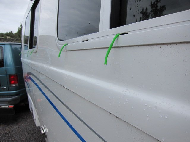
Tracing leaks is a real challenge. Up in the attic, behind the side panels, there is a lot of wiring (the dreaded Oliver sign and the marker lights to name two). On my trailer, no drip loops were employed on these wires. So when my rear Oliver sign started to leak, as well as my streetside marker light, the water did not go straight down but traveled along the wires horizontally to a low spot where they dripped. In my case, this was out the rear streetside ceiling speaker, which is right over my head when I'm sleeping! This is all just to say that, water can travel a long ways before it finally comes to light. I would tape the Oliver sign and the marker light as one other test. As Steph and Dud B mentioned, water is still getting in from somewhere, even though you sealed the interior of your window, which you shouldn't need to do. Regarding the window weepholes, This was discussed a while back. They are not so effective draining water due to capillary attraction between the narrow slots and the water. What I ended up doing to solve this was to cut some short pieces of paracord and stuff one end into the slot. It acts like a wick and you'd be surprised how much water they will suck out of the track in a heavy rain, and they do it quickly. I know about heavy rain here in the PNW (well, it used to rain here....)! So, you may also want to try this hack to stop the leak. Good luck, Dave
-
LOL, yes that's exactly what was missed by inches! Just couldn't figure a polite way to explain it! Dave