Minnesota Oli
-
Posts
108 -
Joined
-
Last visited
-
Days Won
4
Everything posted by Minnesota Oli
-
I have used it in my Oliver storage shed that I heat to only to 55 to 60 degrees, I store my garden produce in the same shed. If I am working on the inside of my Oliver and I want to heat it up that is what I used and it does a very nice job. I have a brother that installed the very same AC when I did mine and he stays in electrical provided spot quite often and he is very happy with the heat pump availability of this AC. So I think if you are going to utilize electric sites it would be a useful feature, It does run quieter and you are saving propane.
-
Spike installed a 9.5 btu in his elite 2. Here is some info that Spike relayed to me. unit: 9.5 • Input needed for cooling: 1370 W • Rated current for cooling: 12.6 A • Maximum power input: 1590 W • Maximum current: 14.6 A unit: 13.5 • Input needed for cooling: 1300W • Rated current for cooling: 12Amp • Maximum power input: 1550W • Maximum current: 14Amp So there's very little difference between the two units as far as power consumed to run them but you would be giving up the heat pump feature that the 13.5 has. When I tested my 13.5 for amp draw, Olivers monitor that is in the attic was reading 10 amps when the compressor was running.
-
John These are made from 6061 aluminum and have been glass bead blasted to help break all the sharp edges from machining, so it gives it a even texture. The leading edge of the eyebrow does have the radius to help deflect any object that would strike it. It could of been a longer taper but I was limited to sheet stock drop I had on hand. I think they are tucked in close enough that the benefit of having them outweighs the risk. The eyebrow with out the mounts weigh in at about 2-1/2 pounds. But this is just the prototype and there is always a better mouse trap. Thanks for the complement and I appreciate your comments. Paul
-
I intended for them to stay in place. They are removable for window maintenance.
-
When I took my first camping trip with the new to me Oliver I was thrilled with the experience it gave me, and as I added more trips I started a mental list of things that I could tweak or add to the Oliver that would make that experience even greater. Today's post is addressing one of the items on that list concerning the windows and how they are limited to only being able to be open in fair weather conditions. Because they lean inward at the top of the window they can create problems in rainy conditions whether the window is opened or closed. When closed they have to deal with all the water that runs down from the roof and sidewalls, this can overload the drainage holes in the window frames which can result in getting the bedding wet. Many Oliver owners have installed rain gutters to help alleviate that problem, but there's still the problem of having the windows open while it's raining to mitigate high humidity or that closed in feeling. What I came up with for a solution I'm calling window eyebrows. I created a list of design parameters or considerations that I wanted to hit for this project. The first one was I did not want to alter the Oliver in anyway, that included the drilling of hole to mount the eyebrow to the windows, this really slowed my project down. I'm the type of guy that builds it in my mind before the prototype is built, I went through many different design ideas before I settled on this one. I designed a mount that clamps into the window frame and to spread the load out over a larger area I utilize three of these mount per window. The mounts are inserted into the window frame and the screw on the bottom is tighten which draws down the 5/16" diameter rod in the tapered slot which then spreads the mount to engage the ribs that are formed into the window frame that hold the rubber molding in place. I inserted a still picture in the following video showing that process. To remove the mount you have to take that screw out with the 5/16" rod and there is a hole on the bottom where that same screw is inserted and when tighten it releases the mount. The eyebrow itself is made of 3/16" thick x 5" wide x 29" long aluminum which has 3/4" of the outer edge turn down. I used a neoprene edging trim bought from McMaster-Carr along the length that mated with the Oliver, my hope was that it could be pushed tight enough to seal the water from coming between the eyebrow and the side of the Oliver making for a easy instillation. When I tested this in the rain it looked like it was going to work but after about ten minutes I noticed each window developed a drop of water by one of the mounts and it would fall and hit against the screen about every couple of minutes. So plan B I was forced to use a 1/4" wide weather strip tape between the neoprene edging and the fiberglass wall of the Oliver. There was one more problem, I had to incorporate a drip edge to the eyebrow to keep the water from following around the edge and falling towards the window. This eyebrow is fastened with two stainless steel 1/4-20 button head hex drive screws to each of the three mounts. This makes for a quick install or removal of the eyebrow, Here in Minnesota we had a warm up and it rained one day so that is all the testing I have been able to do, so time will tell if all is well with the design. As far as the rigidity of the eyebrow I'm extremely pleased you can literally grab onto them and push and pull with no flex of the eyebrow. EYEBROW.mp4
- 18 replies
-
- 14
-

-

-

-
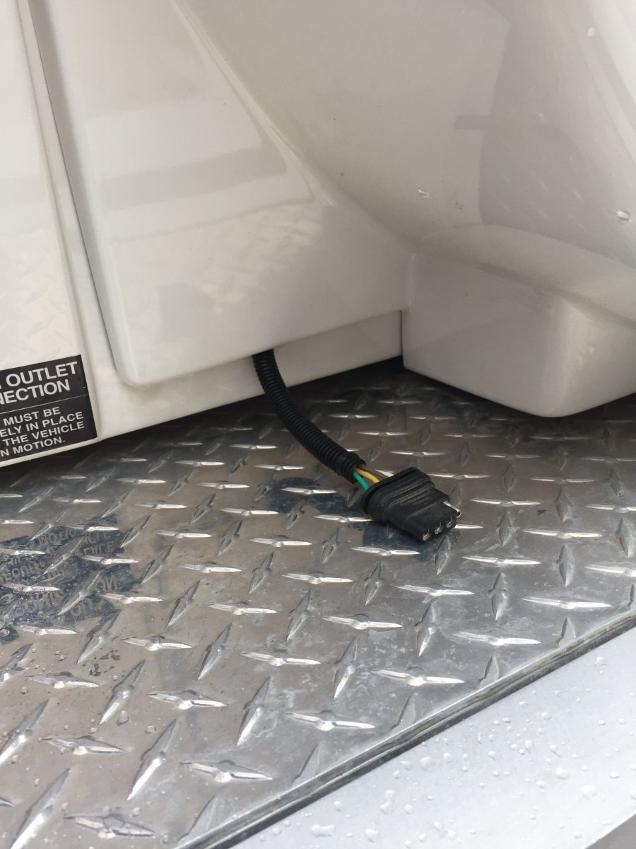
 Don There is a wire that goes out the back to the light for the license plate, there is plenty of room to run the extra wires and this is all very accessible. Paul
-
On my Oliver there are two inline fuses, one just inside the wall where the wire comes in from side wall solar port and if you follow that wire as it heads to the battery compartment, there is a second inline fuse just below the battery compartment. Why mine end up having two I don't know.
-
I thought I would mention I ran into the same problem when I hooked up my Zamp 230 watt portable panel. It is rated at 12.6 amps and I blew the 10 amp fuse so I checked wire size and length and found that I could switch to a 15 amp fuse. I thought that would do it but no It showed I was still not connected to the battery. Checked the fuse and it was not blown, a real head scratcher. It ended up having two inline fuses installed on the positive wire between the battery and the side solar port. I changed that 10 amp fuse to a 15 amp and I was good to go. My Oliver is a 2019 so I don't Know if yours is wired the same way or not but I thought I would share.
-
This is what I love about Oliver forum, topics get summited and people may or may not choose to partake in the discussion but a lot of people take the opportunity to learn or confirm or disagree with what gets discussed with out having to be part of the discussion,I find it to be a great tool.
-
Ray This is what I use and I use it for all my trailers that I have and It has the ability to switch to what ever ball size you need. It's great to know at a glance what your tongue weight is especially when positioning equipment on flatbed trailer . I bought my Oliver gently used and it came with the Anderson hitch system. I pull with a Chev 3/4 ton so I do not use the Anderson and I kept the 2 inch receiver on the Oliver and it pulls like a dream. Product Experts Available Now! Call 800-298-1624 Customer Service Order Tracking Towing Sports & Rec Trailer Vehicle RV & Camper Marine Brands Deals Select Vehicle Go Free Shipping on Orders Over $99* Only 15 Hours 45 Minutes Remaining *Available Within The Contiguous USA Trailer Hitch Ball Mount Weigh Safe Fits 2-1/2 Inch Hitch Adjustable Ball Mount Drop - 4 Inch Rise - 5 Inch Weigh Safe 2-Ball Mount w/ Built-In Scale - 2-1/2" Hitch - 4" Drop, 5" Rise - 18.5K Item # WS4-25 (1125 Reviews) Retail:$362.70 Our Price: $309.00 You Save: $53.70 This item qualifies for Free Shipping Estimated delivery to MinnesotaChange Tuesday, February 15 - (Free Shipping) Monday, February 14 - (1 Day Shipping) Quantity: In Stock drag to rotate Product Images Show All (16) Product Images In Use/Installed Customer Photos Videos Weigh Safe Ball Mount with Built-In Scale Review Weigh Safe Ball Mounts - Adjustable Ball Mount - WS4-25 Review Need help with installation? Locate installers near me All Info Reviews (1125) Q & A (17) Related Parts Photos Why etrailer? Weigh Safe Trailer Hitch Ball Mount - WS4-25 Fits 2-1/2 Inch Hitch Adjustable Ball Mount Drop - 4 Inch Rise - 5 Inch 2 Inch Ball 2-5/16 Inch Ball Two Balls Class V 18500 lbs GTW Built-In TW Scale Weigh Safe Aluminum Shank - Silver Stainless Steel Ball Measure your tongue weight to determine if you can safely tow by simply coupling your trailer to this ball mount. Ball platform locks to shank. Tow up to 8,000 lbs with the 2" ball and up to 18,500 lbs with the 2-5/16" ball. Features: Ball mount with included hitch balls lets you hook up your trailer to your tow vehicle Shank slides into hitch receiver Ball provides connection point for trailer coupler Tongue weight scale built into the ball mount platform helps you balance your trailer Promotes safe towing - lets you know if your load needs to be adjusted before you tow Simple operation - automatically provides a measurement every time you couple your trailer Efficient and hassle-free - eliminates the need for separate or commercial scales Adjustable height lets you tow trailers of different heights with the same vehicle Slide ball mount platform up or down shank and secure in place with included dual locking pins 2 Keys are included 2 Different-size hitch balls let you tow trailers with different coupler sizes To switch ball, simply remove the ball-retaining lock pin from the platform, insert ball, and reinsert pin 6061 T6 billet aluminum shank and mounting platform provide superior strength and durability Solid block construction provides greater strength than hollow steel competitors while also maintaining a light weight Rustproof for a clean finish that stands the test of time Stainless steel hitch balls are corrosion resistant Hitch pin and clip or hitch lock sold separately SAE J684 certified and VESC Regulations V-5 compliant Made in the USA Specs: Application: 2-1/2" x 2-1/2" trailer hitch receivers Gross towing weight: 2-5/16" Diameter hitch ball: 18,500 lbs 2" Diameter hitch ball: 8,000 lbs Tongue weight: 2,200 lbs Distance from center of hitch pin hole to center of hitch ball: 8-3/4" Maximum drop: 4" Maximum rise: 5" Incremental height adjustment: 1" Scale gauge diameter: 1-1/2" Warranty: Limited lifetime for ball mount 1-Year limited for scale gauge This Weigh Safe ball mount has an easy-to-use, built-in scale that measures your trailer's tongue weight every time you tow. If the scale indicates that your tongue weight is too low or too high, you can adjust it before you head out so that you can complete your journey with the peace of mind that your setup is safe. What is Tongue Weight? Tongue weight (TW) refers to the weight that the fully loaded trailer exerts downward on the hitch ball of the tow vehicle. Tongue weight is typically 10 percent - and should not exceed 15 percent - of your gross trailer weight. For example, a 10,000-lb trailer should have a tongue weight between 1,000 lbs and 1,500 lbs. You can adjust the tongue weight of your trailer by removing or adding cargo, or redistributing the load on the trailer. The tongue weight should not exceed the capacity of your tow vehicle, your hitch, or any of your towing components. Why is Tongue Weight So Important? Simply put, too little tongue weight can cause trailer sway and too much tongue weight can cause the tow vehicle to perform poorly. You may have difficulty steering, gaining traction, or braking when driving a setup that has too much weight pushing down on the rear of the vehicle. Ultimately, towing with an improper tongue weight can cause you to lose control of your vehicle or cause your trailer to separate from the vehicle. Built-In Tongue Weight Scale The Weigh Safe ball mount's built-in scale signals you to adjust your load before you hit the road, resulting in a much safer and enjoyable towing experience. Before this ball mount, gauging your trailer's tongue weight was a hassle. You had to rely on inefficient bathroom scales, make a trip to the weigh station, or purchase a separate tongue weight scale. But with the Weigh Safe's built-in scale, measuring your tongue weight is as easy as coupling your trailer to your ball mount. Simply hook-up your trailer to the Weigh Safe ball mount just as you would any other ball mount. The weight of your trailer will push down on the hitch ball, which in turn pushes down on an internal hydraulic piston that sits on a bed of oil. When the piston drops into the oil, the pressure reading is sent out to the scale. Easily Adjusts to Fit Your Setup Adjusting and setting up the Weigh Safe ball mount to work with your specific trailer is easy. First, unlock and pull out the dual pins and remove the platform from the shank. Next, pull out the hitch ball retaining pin from the back of the platform and insert either the 2" or 2-5/16" hitch ball. A 1-7/8" hitch ball (WSB-L - sold separately) is also available. Then reinsert the retaining pin to secure the ball to the platform. Replace the platform and slide it along the shank to the desired height. Insert the dual pins and use one of the included keys to lock the pins in place. The Weigh Safe ball mount can be used in either the drop or rise position to best suit your application. Superior Aluminum and Stainless Steel Construction From the first moment that you lay eyes on the Weigh Safe ball mount you'll see that you're getting a superior, well-made product. The Weigh Safe's shank and ball mount platform are made entirely of 6061 T6 billet aluminum, which is the same material that is used to build aircraft components, automobile frames, and freight liners. This type of aluminum is known for having superior strength while maintaining its light weight, which makes it highly desirable over hollow steel components. 6061 T6 aluminum is also rustproof, which means the Weigh Safe hitch will maintain its clean, shiny, and impressive appearance for years to come. And the hitch balls are made of solid stainless steel, offering far greater protection against rust and corrosion than other steel hitch balls that are only painted or plated on the surface. The Weigh Safe ball mount meets VESC V-5 regulations and is SAE J684 certified. These regulatory bodies - the Vehicle Equipment Safety Commission and the Society for Automotive Engineers - create standards for the design, construction, and performance of automotive and towing accessories. Weigh Safe has had this ball mount thoroughly tested in simulation to ensure that it complies with these standards. The result is a strong, safe, sturdy product that is built to last. WS4-2.5 Weigh-Safe Trailer Hitches with Tongue Weight Gauge - 2" x 2-5/16" Ball Combo - 4 Inch Drop - 2-1/2 Inch Hitches
-
Hot Water At The Bathroom Faucet
Minnesota Oli replied to Minnesota Oli's topic in Ollie Modifications
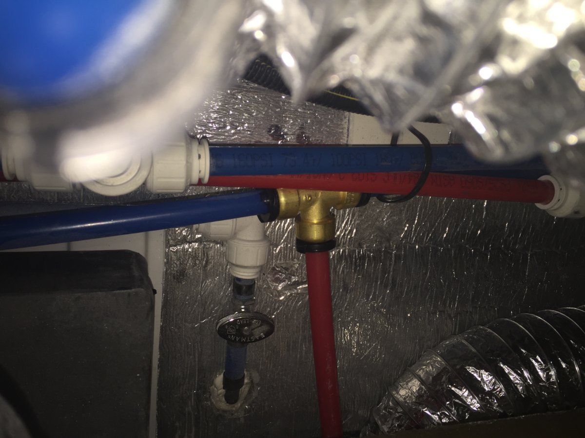
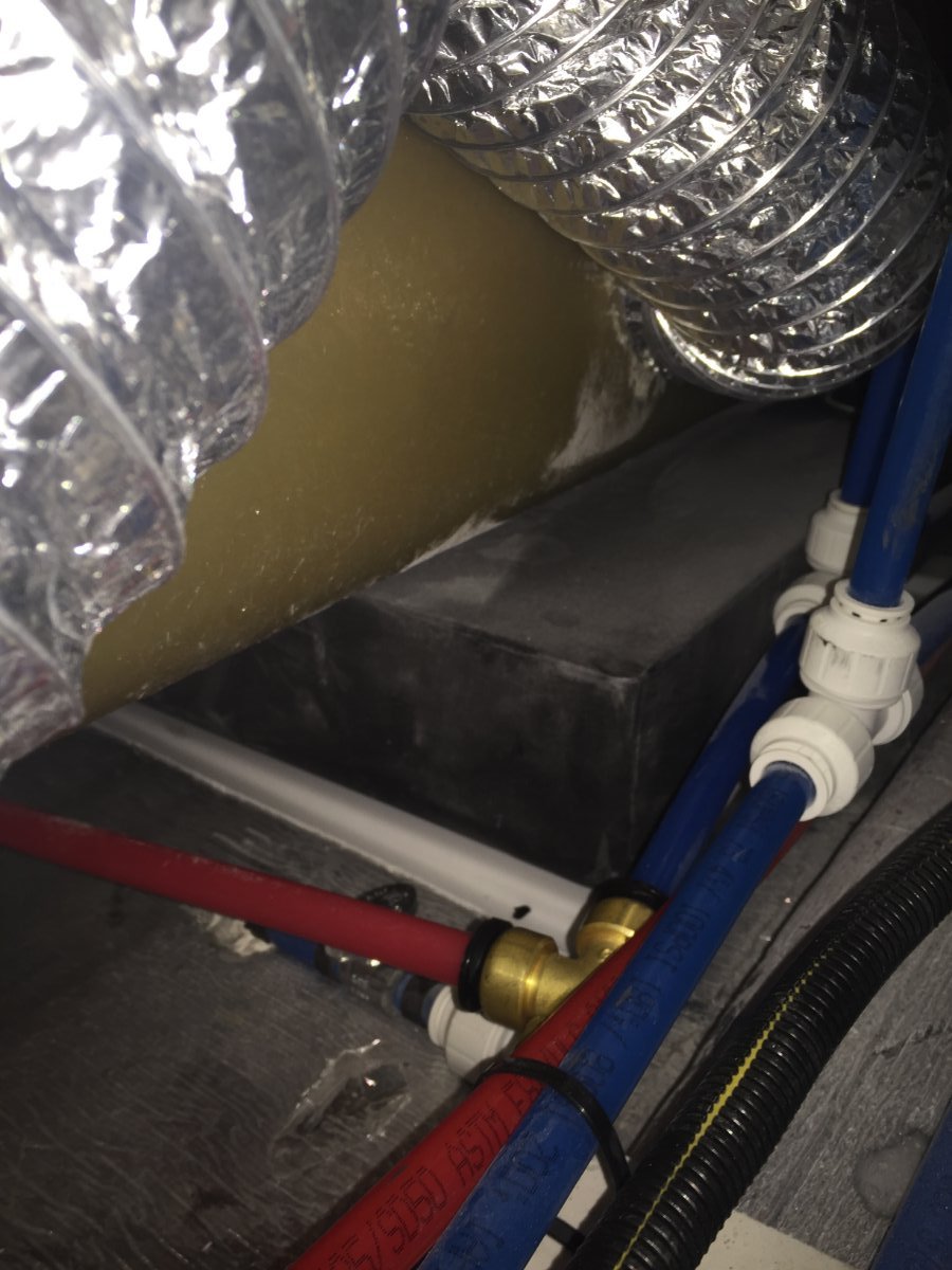
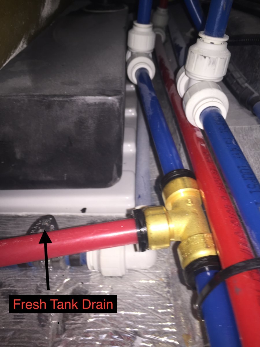
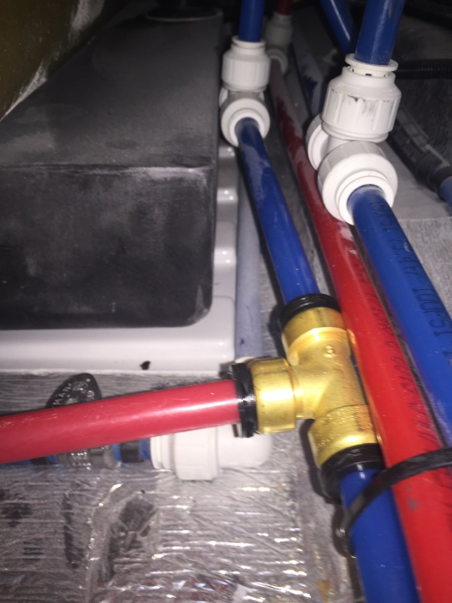
Hey Mossey I originally tried to run the line up the curb side but ran in to a obstruction about by the door, figured it had to be some kind of support for the floor. I tried going from both ways but had to abandon it. Starting from the bathroom and running it down along side the drain pipe for the black tank work out really well and once clearing the end of the grey tank it is wide open to cross over to the curb side. The plumbing part of the job went really fast compared to the wiring side of the job. To be honest I never checked out going back to where the fresh water line comes into the trailer. Here are some pictures of where I tee into the fresh water fill line a short distance before the tank.
-
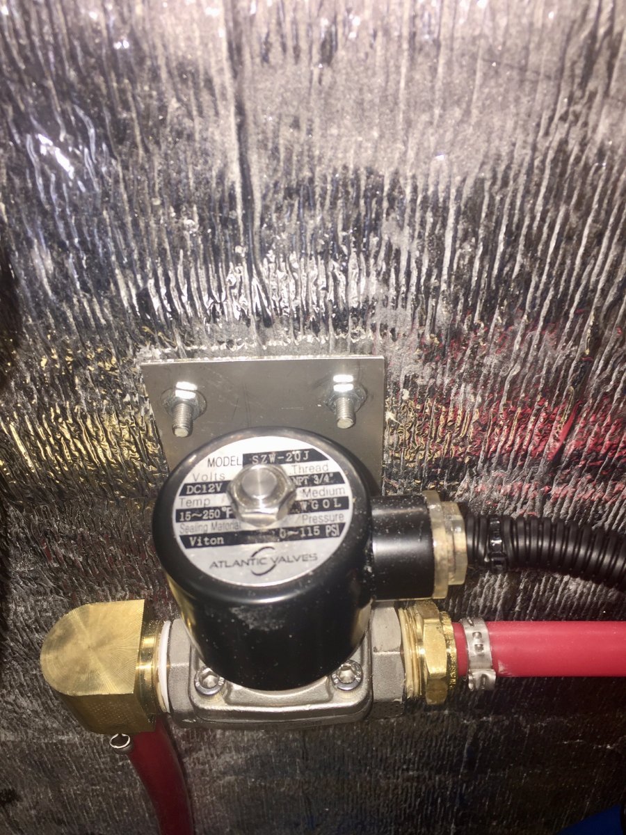
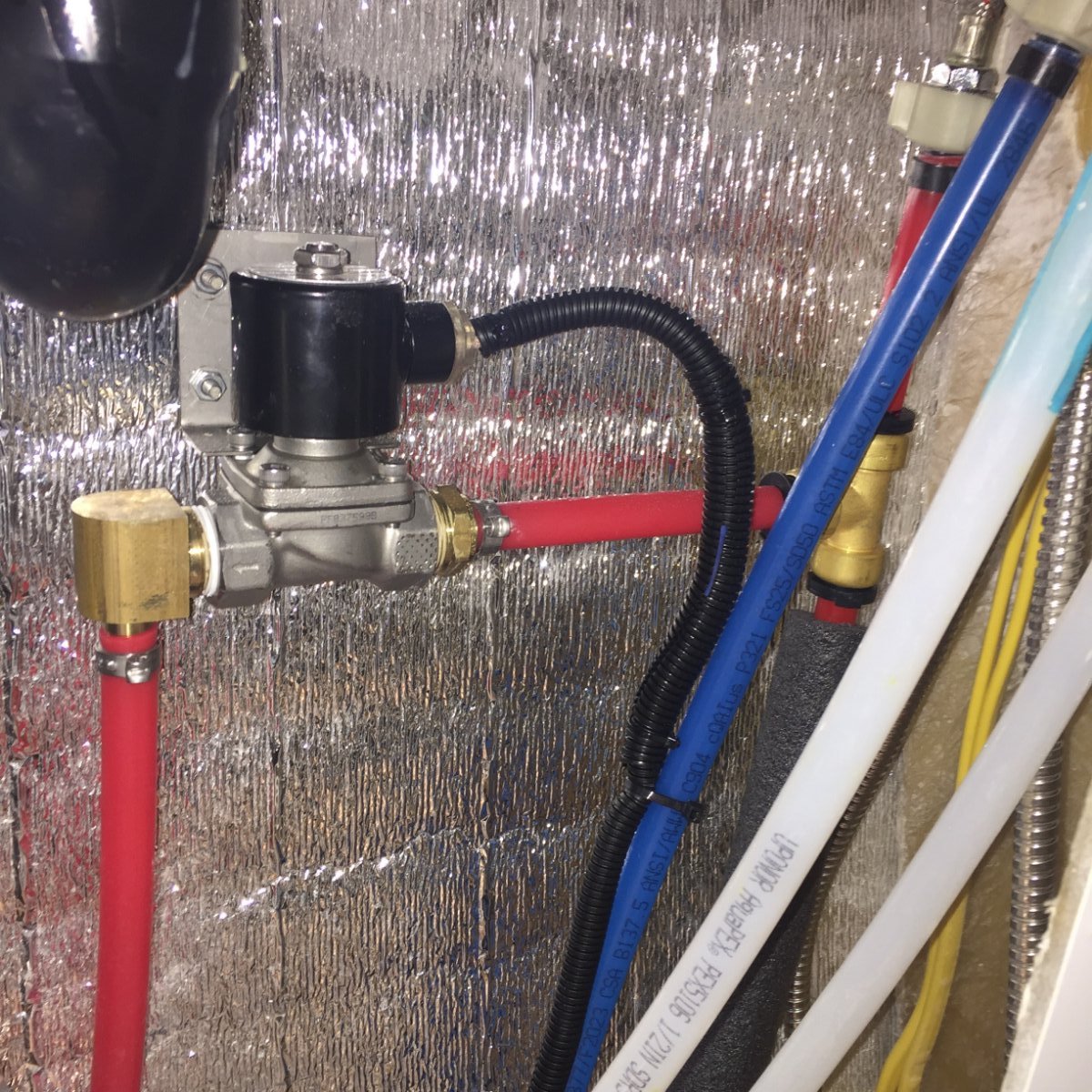
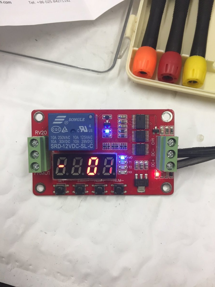
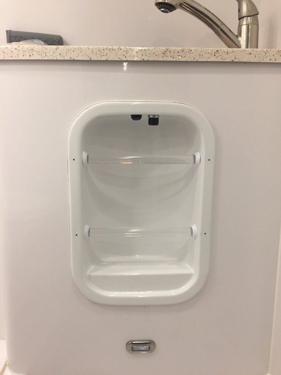
It always bothered me especially when getting ready to use the shower the amount of cold water coming out of the faucet and heading to the grey water tank. So when Overland put up a post back on January 3 titled Truma Comfort Plus via Modification, it got me thinking. I went out to the Oliver and tested actually how long and how much water was being used before getting hot water to the faucet. My results were 14 seconds and a volume of one quart and I thought that's not that bad. But then why does it bother me when I'm standing there waiting and then I think about how I'm just transferring my fresh water to the grey water tank and how many gallons go this way during a camping trip. So for the next week the subject was percolating in my mind and I came up with some ideas and settled on what I thought would be feasible solution. I installed a normally closed solenoid operated stainless steel water valve. I made a bracket out of stainless steel that I attached to the valve and then utilized the four bolts that were protruding through the front of the camper that help secure the cover for the propane tanks. I installed a tee in the hot water supply line just in front of the faucet and run 1/2" pex between it and the valve. Next I ran 1/2" line following the black tank drain pipe towards the back of the trailer and crossing over to the curb side and then teeing in to the line that fills the fresh water tank. Next I planed on putting a switch to operate the valve next to the switch that is mounted on the vanity towel rack that operates the water pump. I wanted to avoid standing there and holding the switch so I found a programmable multi function time delay relay module UCTRONICS model U6030 to allow me to accomplish this. This module is inexpensive about $12.99 but is very flexible ,it has 18 programmable delay modes with two settable timers. The static current is just 5.5 mA. I wanted this module to only be powered up when the water pump was turn on so I brought power from the water pump relay, this way both switches activated the module. This module also needs to have a 12 volt power supply to operate the water valve, so I ran a wire from a unused slot in the fuse box under the dinette, the valve draws 1 1/2 amps. I was a little worried about getting the module programmed for my needs, we all know how Chinese instructions are poor due to the language translations, but it went really well. IMG_1387.MOV I mounted the module in a 4"x4" waterproof box and put that under the front dinette seat,that way I had access to it in case I need to change programming. The last picture is of the vanity and the switches for the water pump and the water diverter valve. I used a waterproof switch I had and I plan on replacing it with a smaller easier to push model. I'm happy with the way it works, flip the water pump on then push the other switch and release, you hear the water pump start and run for 15 seconds, it will shut off and you have hot water at the faucet.
- 18 replies
-
- 13
-
-

-
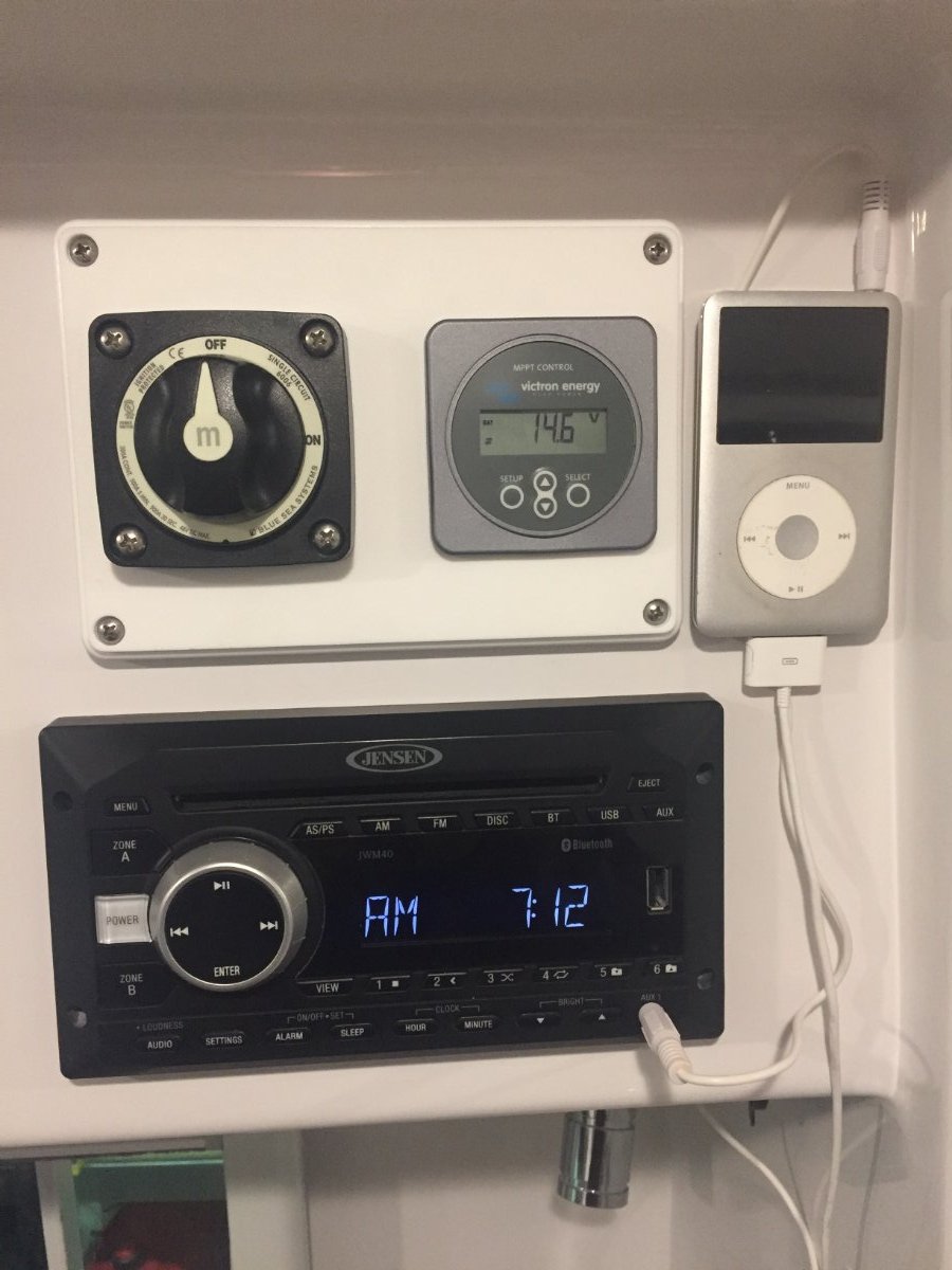
Mine is a 2019 and was set up the same as Mossey. I also added a disconnect switch before the charge controller and a circuit breaker after charge controller. Here is a pic of disconnect switch and Victron charge controller monitor.
-
Kirk I will give you another option to consider, the method I used was to add two additional heat runs from the furnace with out cutting holes or adding fans. I believe the furnace also runs a little quieter because the fan is not fighting to push air through only two heat ducts. I tested this modification in subzero weather for 2 1/2 days with full water tank and water pump on. The trailer temperature was more balanced with the bathroom staying cozy warm and the street side wall along the bed was not chilly. The coolest area in the Oliver was the closet. Here is a link to Breaking Subzero Oliver Furnace Mod Paul
-
Lithium Pro Package vs Solar Pro Package
Minnesota Oli replied to John Dorrer's topic in Welcome to the Oliver Forums
The control board for the thermostat is mounted on the AC unit. So when you set thermostat to heat it sends a signal to the control board that is mounted on the AC which then sends a signal to the furnace control board which then initiates the start up of the furnace. The work around I mentioned earlier in this post is a way you can make this work without having to pull more wires. -
Lithium Pro Package vs Solar Pro Package
Minnesota Oli replied to John Dorrer's topic in Welcome to the Oliver Forums
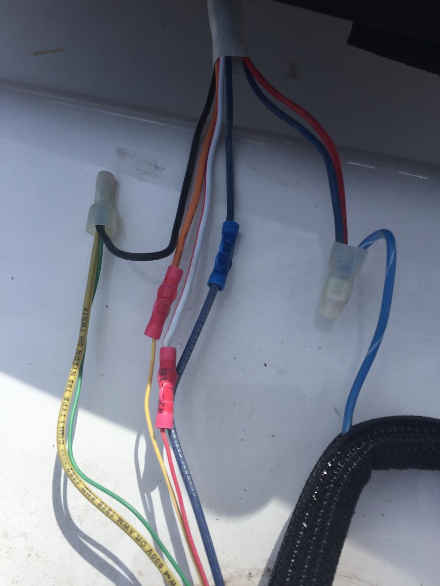
Minnesota Oli Members 67 Author Posted September 24 Here's a paragraph from Got Earplugs by katanapilot from My version of the Houghton AC install posted May 27. As a sidenote halfway through the install I thought of a different way of doing the wiring for the thermostat. If a person replaced the LCD thermostat with a older manual style you could do away with the LCD relay board. If you look at the first picture that shows a group of wires that are in a black sheath, these are the control side of the wiring for the AC. In that group of wires there are two blue wires one with a white stripe. The one with the white stripe is hot 12 volts DC and the solid blue is the wire that goes to the furnace relay board. So re-allocate the existing thermostat wires by doubling them up ,two of them hooked to the solid blue and the other two hook to the blue with the white stripe. Then at the wall hook the two thermostat wires that are hooked to blue with white stripe to the power in on the new manual thermostat and the other two to the power out. The reason I would double them up is because of they're small gauge. This would do away with having to pull wires and using the LCD relay board. Also save you having to toggle through the unusable modes (heat strip, cool) on the LCD thermostat to get to the furnace mode. By re-allocate the existing thermostat wires and doubling them up ,two of them hooked to the solid blue and the other two hook to the blue with the white stripe. Now you are able to utilize wires that are already there saving you having to run new ones. Simply switch out the thermostat with one that does not need a control board. Paul https://www.recpro.com/rv-air-conditioner-low-profile-13-5k-quiet-ac-with-heat-pump-remote-non-ducted/
-
PLACEMENT OF VICTRON BMV-712 BATTERY MONITOR?
Minnesota Oli replied to Spike's topic in Ollie Modifications
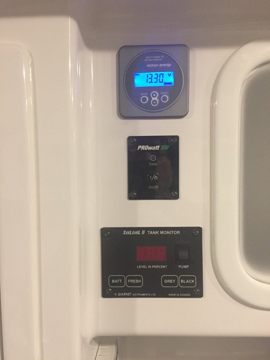
I have a 2019 Oliver #475 and there was this spot open to use for mounting the monitor. I admit that the app for the phone is much more user-friendly but for a quick look or for some reason your phone is not working or available I still would not want to be without the monitor. The shunt for the monitor is located in the battery compartment so the area I picked for mounting the monitor is directly above it, although it was challenging to connecting the wire between the shunt and the monitor. Looking into the pantry door, the inside corner to the front of the trailer is where you will drill down through three layers of fiberglass, pantry inner shell, pantry outer shell, and base cabinet. Then drill a hole through the side of pantry inner shell. Now use the drill to cut a trough between the two holes. The drill needs to be sized to allow the plastic terminal on the end of the cable to pass through the hole. Now using a fish tape pull the cable up from basement into the pantry. Then from the access hatch on the top of the pantry side wall feed the fish tape down between the walls to the hole you drilled in the side of the inner pantry shell. Now you can pull the cable the rest of the way up to where the monitor will be mounted. You will notice that the back side of the hole for the monitor is in a area that transitions to a different wall thickness in the middle of the hole so I used the threaded ring on the back in combination with the front mount that is provided with the monitor.
-
Lithium Pro Package vs Solar Pro Package
Minnesota Oli replied to John Dorrer's topic in Welcome to the Oliver Forums
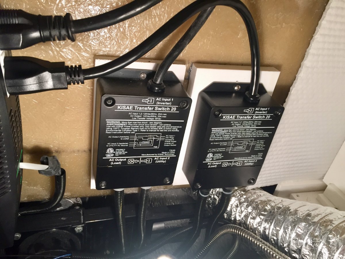
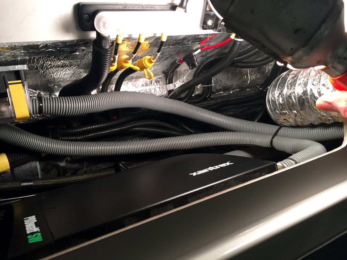
This is how I ran the AC with the 2000 watt inverter. I added anther transfer switch to operate the AC circuit on my 2019 built Oliver. Posted September 7 Besides the huge improvement in the sound level there is also another area where it surpasses the Dometic AC that I had replaced. The Houghton with the compressor running draws 10 amps while the Dometic was pulling 16 amps. So I decided to install a second transfer switch for the air conditioner to test it running off the batteries. It was 11 o'clock in the morning on a cloudless sunny day the temperature was 88 degrees. I had my batteries 400 Ah fully charged with 340 watts on the roof and 230 watts remote ready to feed it. I set the thermostat at 70 degrees and turned on the AC. Once it brought the temperature down to 70 I noticed it was cycling four minutes on with the compressor and four minutes off. I left it running until about 5 o'clock and was surprised to see that the batteries were at 97 percent. So I was happy with those results but time will tell if that is the norm. I put the picture in to also show it's nice low profile. Paul
-
Closing the Gap | Mud Flaps Mod
Minnesota Oli replied to Minnesota Oli's topic in Ollie Modifications
Yes this was done on a knee mill that I retrofitted with a 2 axis cnc kit. Now this is very helpful for making these pieces for this project but since there are only two pieces and the winter is long there is no reason why they could not be fabricated with hand tools similar to making the pieces out of wood. By this I mean drill press, band saw, drum sander, and the like. I'm very happy with the outcome of the project. Earlier this year I took Oliver into places that I probably shouldn't have, another words I was a little concerned at the time but afterwards all came out fine.Places like Rabbit Valley, Colorado and Moab, Utah, I'm talking a lot of deep ruts in the roadway and lots of rocks and the mudflaps survived with no issues. They do a great job of protecting the complete under side of the trailer beyond the wheel wells. -
Upgrade To Lithium's Request For Info
Minnesota Oli replied to Geronimo John's topic in Ollie Modifications
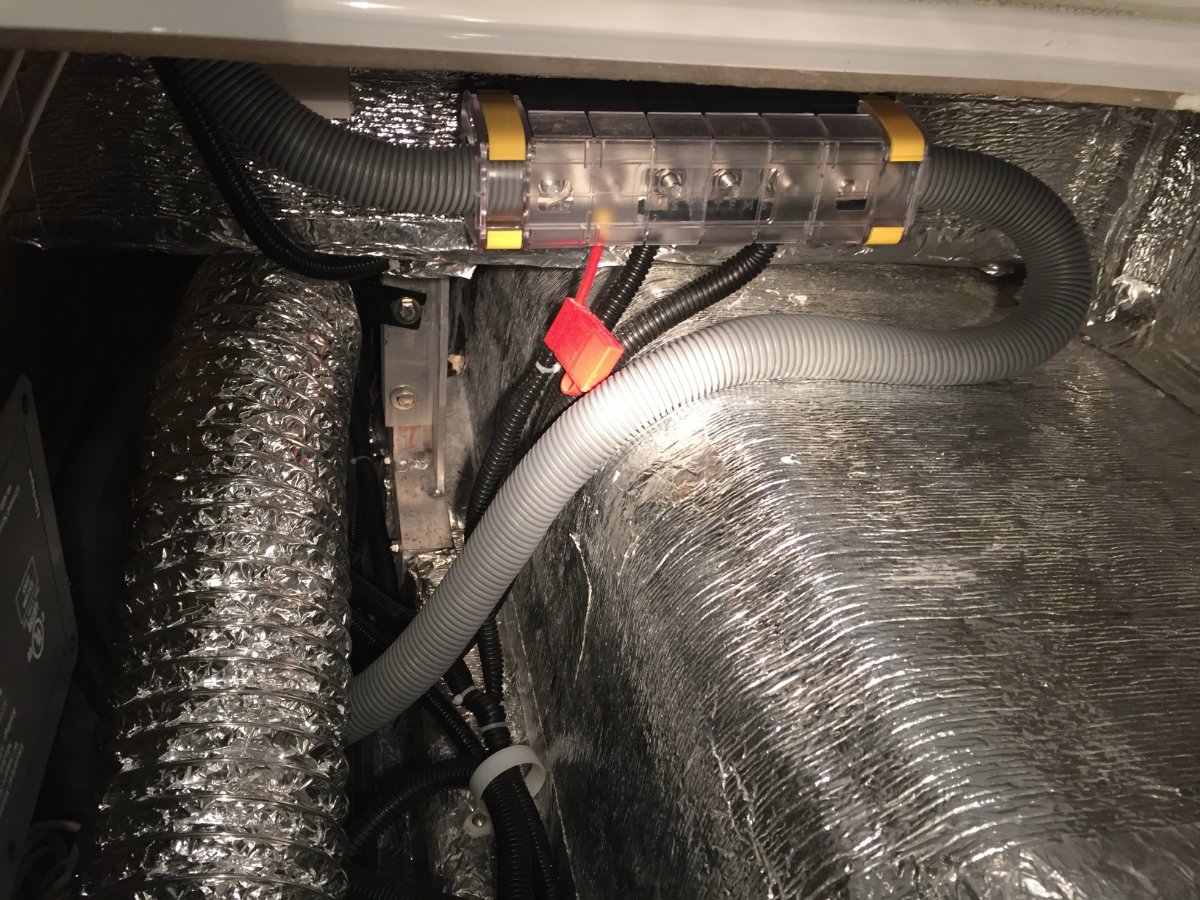
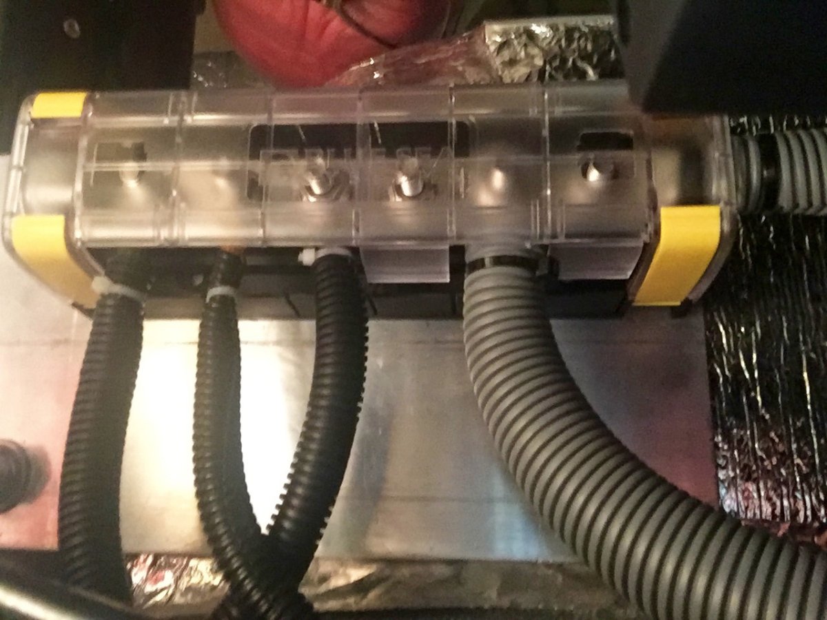
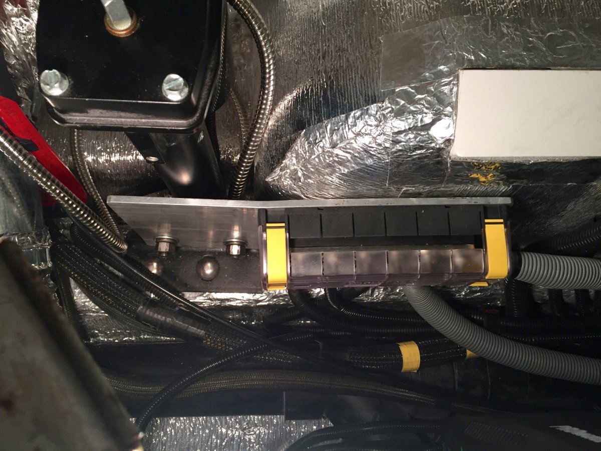
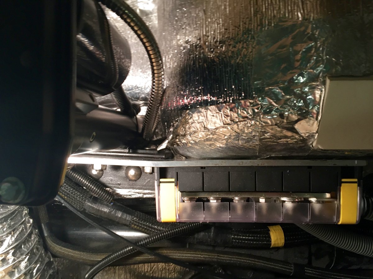
Members 63 Author Posted February 1 (edited) https://www.bluesea.com/products/2718/MaxiBus_Insulating_Cover_for_PN_2105_and_2126https://www.bluesea.com/products/2126/MaxiBus_250A_BusBar_-_Six_5_16in-18_Studshttps://www.amazon.com/Battery-Spartan-Power-Negative-Terminals/dp/B07MXQSNHR/ref=sr_1_5?dchild=1&hvadid=77859219137661&hvbmt=bb&hvdev=c&hvqmt=b&keywords=spartan%2Bcable&qid=1612200841&sr=8-5&tag=mh0b-20&th=1 Well I want to try to answer to this request. Its a project that requires you to cover a lot of ground so I decided to break it down to individual aspect of the project. So I am standing at the side of the Oliver looking at the open battery compartment. I see this maze of cables and I am thinking of a discussion on the Oliver Forum. It was suggesting that there could be a improvement to this maze of cables by installing bus bars, one positive and one negative inside the basement of the Oliver. This would allow the cables from the various components such as Zamp Solar Controller, Side wall solar Port, Progressive Dynamics Power Center, and the chassis ground to be routed to the relevant bus bar. With that done it would only leave the positive and the negative 4/0 cables leading to to the battery compartment from each perspective bus bar. With that said the only other cables that my set up has is the one that leads from the Victron BMV-712 battery monitor to the remote display. I also have a now unused wire that was for the temperature probe that was hook up to the Zamp solar controller. The service person at Battle Born advised to disconnect this at the Zamp solar controller, I did leave the unhooked wire in place for possible future use. I then went inside to determine the placement of the bus bars considering the number and lengths of cables that need to be relocated and how I was going to attach them in the Oliver basement. I was looking at the positive 4/0 cable coming in to the basement from the battery compartment then going to the main fuse block and then continuing on to the inverter. That is when I thought about swapping out the fuse block with the positive bus bar sense the 4/0 cable is already run and no need to make up positive 4/0 cables. It also had a mounting block already in place. This meant I could move the main fuse out to the battery compartment next to the positive battery post to better protect the wiring. This was another topic I remember following on the Oliver Forum, so much information to be had. I looked at how the various cables were run into both sides of the battery compartment and they had positive on one side and negative on the other. So it made sense with the wire lengths the way they were to try to find a spot to mount the negative bus bar in the compartment under the street side bed. I started looking for a place or a way to do it with out having to glue a block to the fiberglass. I noticed two 1/2" bolts that were used to mount the street side stabilizer to the frame. I used a 1/4" aluminum flat that was 6" X 14" long. I then drilled holes to match the stabilizer mount. I then had to put a slight bend about 5" from the end so the plate would run parallel to the wheel well. That is where I mounted the negative bus bar. When I pulled the cables back out of the battery compartment I was able to do it with out removing the terminal ends. Some I had to bend slightly to get them through the cable glands, but this saved me from having to mess around with installing new ones. All the wires turned out to be the right length except the positive wire from the remote solar port. I was able to shorten that wire where there was a inline fuse and add a ring terminal. The negative 4/0 cable that went from the battery to the inverter was then rerouted to the negative bus bar. The only cable I had to buy was a three foot 4/0 to go from the negative bus bar to the inverter.
-
There's probably a lot more that comes in to play when components are chosen for the Oliver, my 2019 has multiple Dometic products so I'm sure the more components the better the over all price point.
-
I just want to mention that earlier this year in April I spent ten days in Colorado and Utah with the Oliver with out shore power. The Oliver had 340 watts on the roof and Zamp 30 amp charge controller. The only up grade was four 100 ah Battle Born batteries and Victron battery monitor. We used the furnace every night, inverter for coffee maker every morning and microwave a few times to thaw food. Plus lights, water pump, fan, music. I brought alone a generator but never needed it. We always had batteries top off with the morning sun. This was a big improvement over my previous experience with the AGM batteries. At this point I am happy that I kept my 2000 watt Inverter, it handles everything just fine including the new Houghton AC with out any of the new inverter charger issues. I recently up graded my roof mounted solar only because I live in MN and can not expect to harvest as much energy as Colorado or Utah. I do think simpler is better, like the Battle Born batteries are easy to use when coupled with Victron battery monitor and a cut off switch, which make it easy to care for off season. So eventually they will work the kinks out but simpler is better.
-
I would agree with SeaDawg, I have recently completed a up grade to roof mounted panels and have had talked to Zamp about recommendations for charge controller for the rated watts of my solar array. They are very helpful and easy to talk to and for my size of system they recommend a mppt charge controller, they said they currently do not have one to offer to me but that in the future they will have one. It was in the process of being developed, I did purchase there panels for my project, I do think they make a quality product and I like the made in USA.
-
A teaser for a new modification in the works
Minnesota Oli replied to Minnesota Oli's topic in General Discussion
Life has a way of getting in the way of working on your projects but I'm getting closer to the finish.
-
Maybe or maybe not. I will be posting about the project under Ollie Modifications when complete.