Galway Girl
-
Posts
753 -
Joined
-
Last visited
-
Days Won
24
9 Followers


Recent Profile Visitors
13,643 profile views


Galway Girl's Achievements
")


-

Confirming Sway Control with HD trucks in 2026
Galway Girl replied to Wayfinder's topic in Towing an Oliver
FYI - This years Ford Towing guide has a ton of useful general info as well. 2026-Ford-RV-&-Trailer-Towing-Guide_r7_fnl-Mar19.pdf -
Confirming Sway Control with HD trucks in 2026
Galway Girl replied to Wayfinder's topic in Towing an Oliver
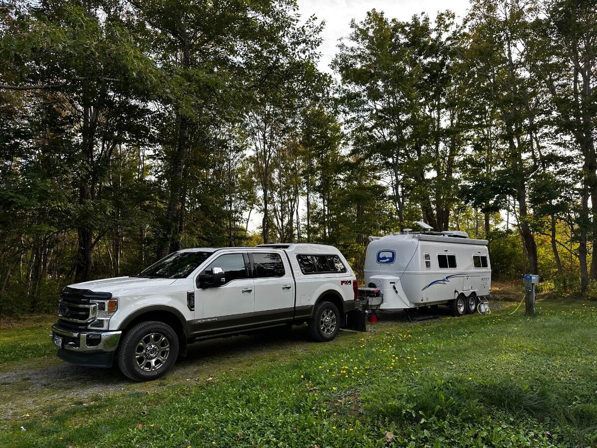
When we first bought our EII we had a F150 with a hitch rating that required load levelers and sway control for any tongue wt above 500lbs. So we bought the Anderson and used it for 2 years...but then we upgraded trucks. We now have an F350 Diesel 1 Ton Short Bed with a 3" receiver which has a dead weight rating of 2120lbs. We use a B&W Tow N Stow hitch and that's it. We've not had any sway or issues and it's dead simple to adjust if needed and hookup/unhook much easier than using either the Anderson Antisway (with Chains) or the types that have WDH Bars and Sway Bars. We don't need sway control as our truck also has braking sway control built in that states in the user manual that manual sway controls shouldn't be used. CS
-
Made in USA leaf springs
Galway Girl replied to Mountainman198's topic in Mechanical & Technical Tips
We have 3.5K Axles and used 4 leaf Alcan, had them do the install, they gave me the 5th leaf to carry with me if we wanted to install it later. After 5k miles with 4 leaves we're just fine. That said if you have the 5K axles on your trailer, then most folks use the 5 leaf version to match the axle rating. -
Yes we made advanced reservations but we found many campgrounds less than 50% occupied by mid September. Probably the best to book in advance at the “National Parks “ as they are the busiest. We were in Canada Sept 5-Oct 1 Weather was very mild , in 55-65F range most days . Nights in 40’s. There were 3 rainy days, but some campgrounds are on bluffs so pretty windy.
-
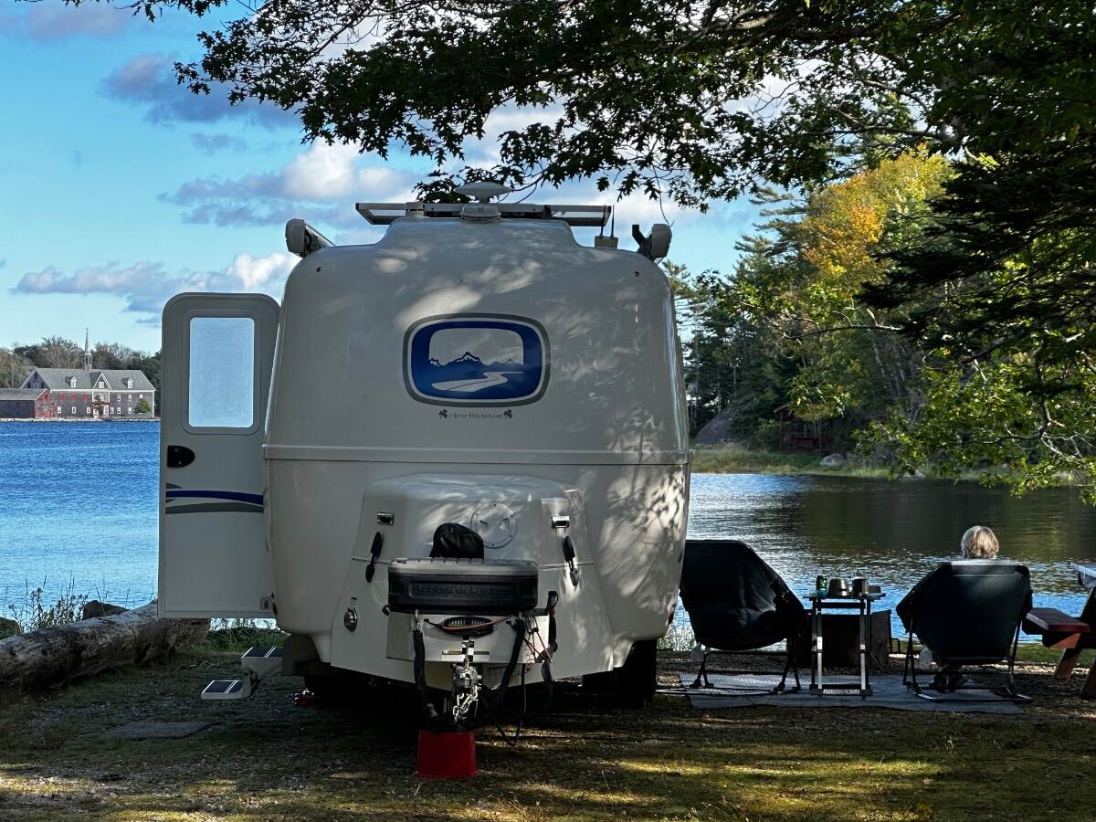
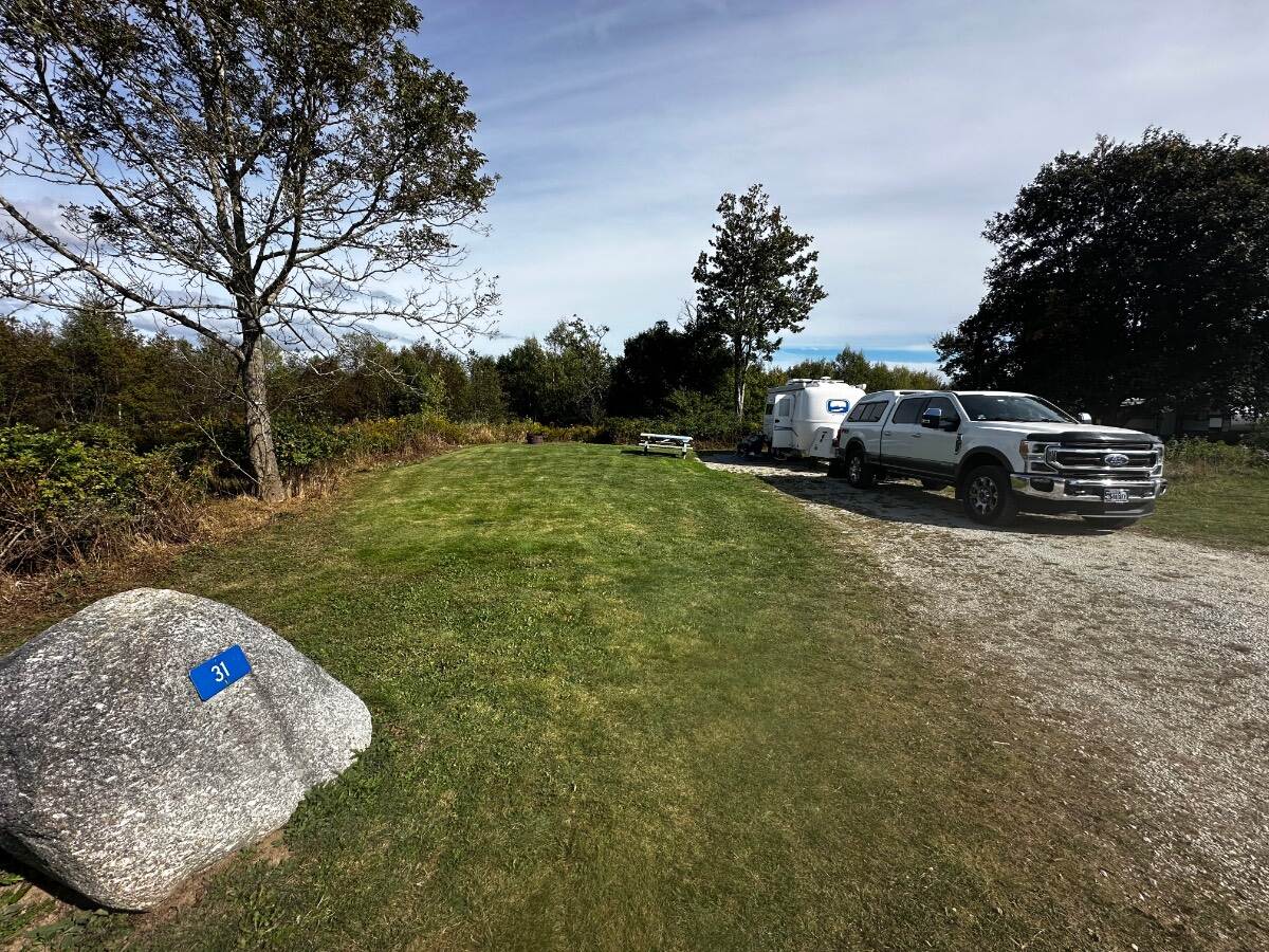
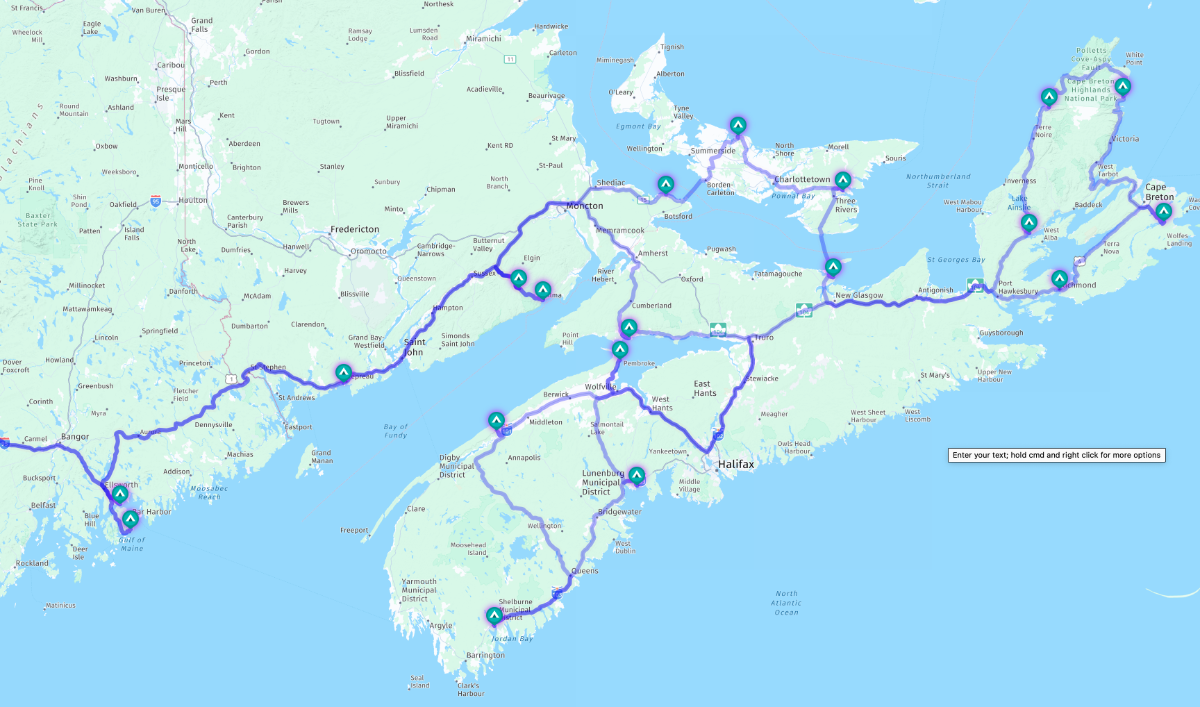
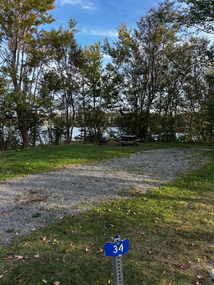
We did a full month long trip in Sept thru early October to the area shown 2 years ago and it was barely long enough. Each of the items with a TENT on the map are highlighted in our trip..."the big loop" and and be seen in pictures with comments here: Scroll down to the pix section on Nova Scotia Main Island. https://4-ever-hitched.com/the-big-loop-2024 Graves Island Provincial Park - Site 31 Shown - is Just South of Halifax on the main island. Puts you perfectly in a spot for the UNESCO site of Lunenburg, Halifax and Peggys Cove as day trips. I would stay there at least 4-5 days if I were doing over. To get into the park you cross a causeway into the park which is on an island. Going south don't miss staying at "The Islands PP" Further SE = Site 54 - Islands Provincial Park - Puts you on the edge of the water....this is on the SE Corner of the main Island. North on the main Island before you cross onto Breton Island you may want to also see the Fortress of Louisburg...which is on the north east side of the island. A good stop point is Mira River Provincial Park as you can easily drive down to Fortress Louisburg from Mira River...and then north after that stop. SIte 28 - Electric & Water at Mira River PP Above....but the site 34 below would fit and is right on the bay, but no Electric or Water... I've labeled all the campsite photos for each park in our blog, but If you have any specific questions we could get on a call. Craig & Rose
-
Maximizing amp hours for boondocking
Galway Girl replied to Olive2Roam's topic in General Discussion
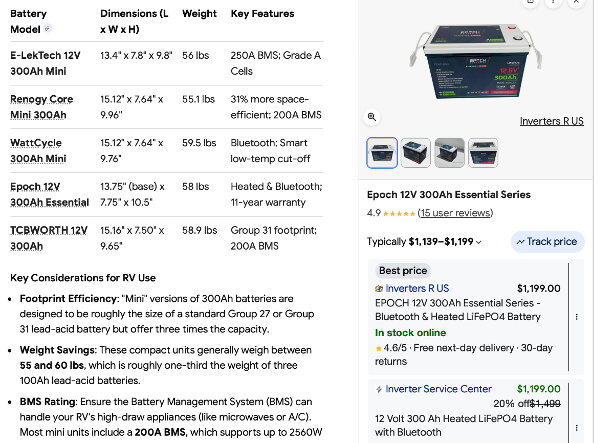
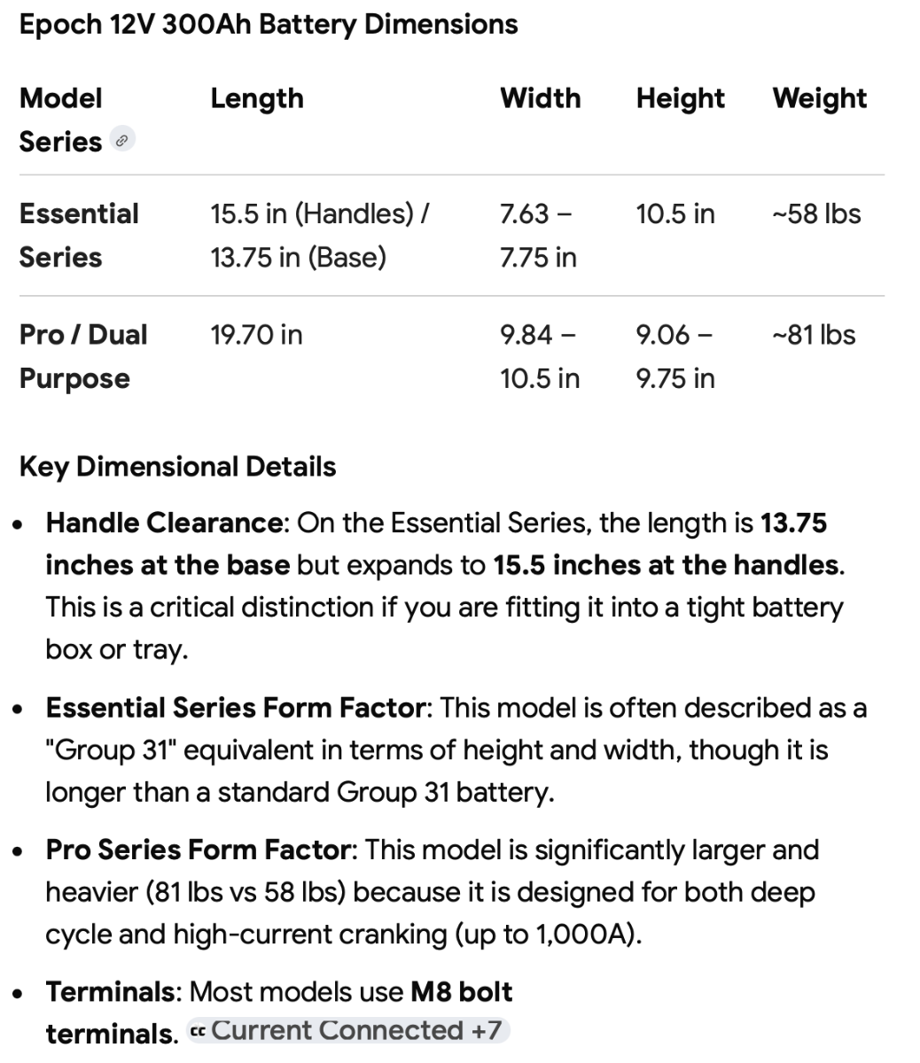
Not sure of the full dimensions of your space in LE1 but you may want to check out some of the 300AH mini batteries like this one from Renogy. Renogy 300AH Mini Core They claim a much smaller footprint ...but be aware,,,this model doesn't have self heating for cold temp charging, but they do have low and high temp cutoffs for protection. List prices are currently $879 direct. Here are Epoch Dimensions Just an idea of others:
-
Put on 50k miles since repair. No changes or movement. Craig hull 505 (Galway Girl)
-
Which connection anchors did you use..for the side of the trailer mount? CS
-
Saw this post from another user...quite detailed. I mounted the sending unit for our system (not Tire Minder brand) on the outside of our front jack power head. You can easily pull 12V from the inside of the power head and decide if you want/need an on/off switch for the circuit. * I just leave mine on all the time...as the draw is minimal.*
-
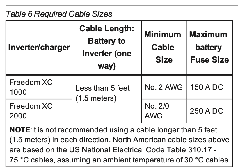
For those with the Xantrex Freedom XC2000 inverter here's that same table. These XC2000 was the unit used put through 2024 with the lower tier battery configurations. Also these units don't allow running the AC off DC. (So these are configurations other than the "Platinum" or dual 320AH Lithionics)
-
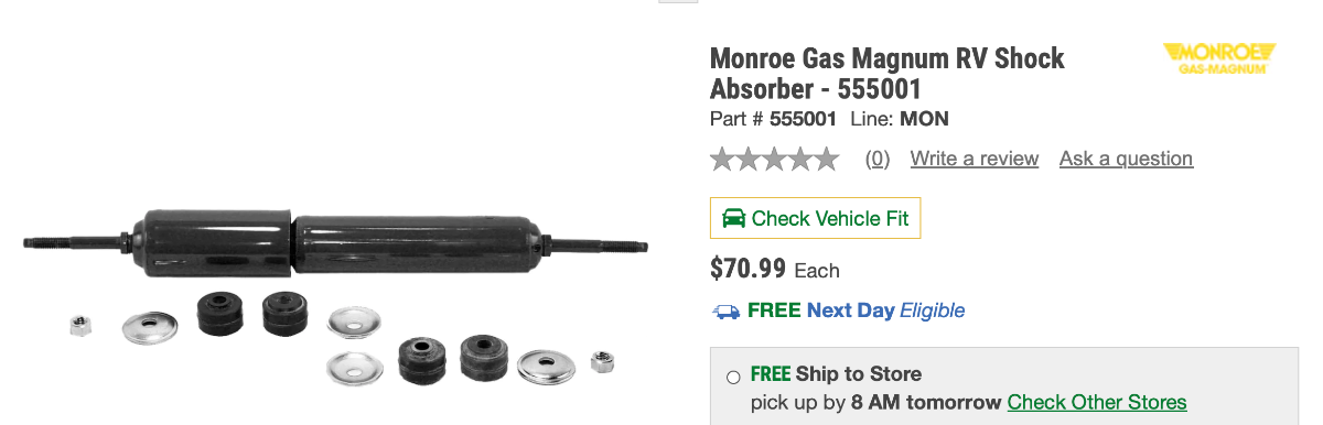
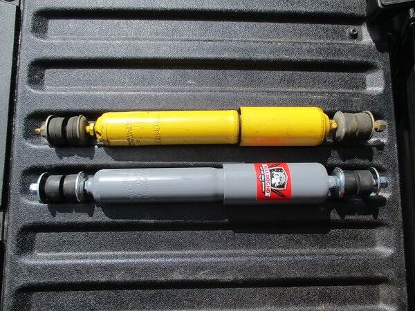
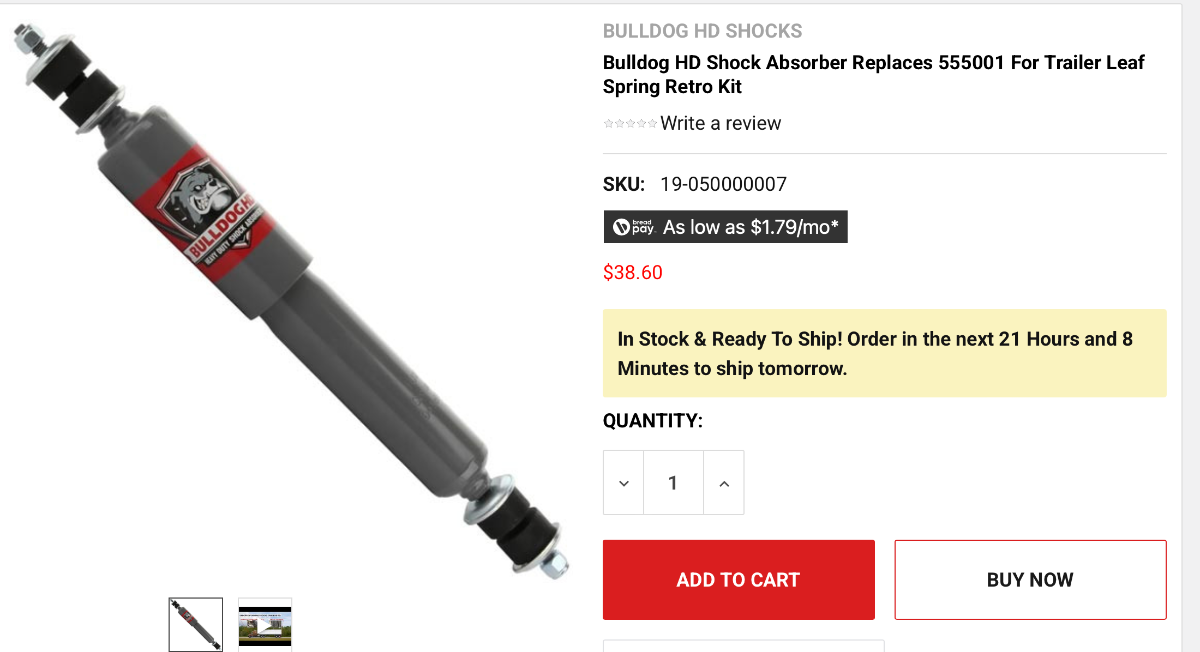
These are the ones shipped from the factory with the trailer: Bulldog Shocks are the ones folks tend to 'upgrade' to if replacing the OEM shocks. Bulldog Shock Parts to Replace Monroe 555001 (OEM) Bulldog part number: HD1213-0656 Price about $150.00 for 4 depending upon supplier. Monroe (Yellow on Top in Pix) Bulldog on Bottom. Link to 4 states truck parts: https://www.4statetrucks.com/bulldog-hd-shock-absorber-replaces-555001-19-050000007 Craig
-
Removing shelf under bathroom sink for plumbing access.
Galway Girl replied to Mroth's topic in Ollie Modifications
To make changes in your signature: Click on your name in the upper right corner of the page. It will pop open this window: Look under SETTINGS and click on account settings. In the settings tab that opens up...near bottom you'll see signature with the pencil icon. Click on that signature line and it will pop open...you can add what you want including maps of your travels, hull # etc. Craig That brass port is the anti-siphon air gap from your black tank flush. The inlet to your external black flush hose bib on the side of the trailer (down low just below the dinette window) runs up to that antiphon then back down to the side of your black tank which is where it connects to the wash head. Once done flushing, that air breaker enables water to drain back out of the inlet port line out the street connection to your flush port. The air gap is an anti suction device that keeps black tank water from coming back out the exterior flush lines. It also makes that line self draining to prevent freeze ups in the flush line. (After you take your hose off after flushing...you'll see about a quart of water drain back out the connection.) Hope that helps.
-
Here’s a blog post we wrote showing the installation of snap pads on our 2019 back in 2020. It is so easy! Blog with installation video
-
Preview for Oliver friends: Since we're between trips with Hull 505, we decided to try out some ai song creation tools and do a road log video. This is the link below is to our page which includes the lyrics for the video shown below: Blog Article with Video and Lyrics Craig & Rose Video from our website below: Oliver 505 640 - SD 480p.mov
-
Hoping for the best for all BB owners.