
jd1923
-
Posts
1,250 -
Joined
-
Last visited
-
Days Won
44
Posts posted by jd1923
-
-
I would replace them with same spec as what was OEM installed. Measure your overall length, count the links, measure the length and diameter of each link.
The only clue that perhaps you have an older hull is "rust" since you have no signature. Live in the rustbelt? Ours was in the MW when first bought, down in AZ for years now and the chains look like brand new shiny chrome. They installed 3/8" hardened chromed links on ours, each link 2" long. Get highest grade available in the correct size. Overall length +/- a link could depend on where the Anderson mounts were bolted into placed.
-
 1
1
-
-
14 minutes ago, Wayfinder said:
@jd1923 any idea about the brake assemblies "ticking" when the truck is in run mode? Was guessing communication/testing of the brakes so the truck always knows the status. It tickets about the same rhythm that the errors might occur on the dash, when the brakes get disabled due to ground issues.
I've not heard any brake ticking in the many trailers I've owned. It does not sound right. However, I have never owned a newer truck with a built-in brake controller, so have no experience there.
I've always installed Tekonsha aftermarket brake controllers in every truck I've owned, except a for Redarc model installed in our GX470.
-
 1
1
-
-
On 7/18/2024 at 8:38 AM, Ray Kimsey said:
I will be following this topic over the next several weeks.
Everything has been said, great info here from many members.
It's a long 17-page read! 🤣
-
5
-
-
21 minutes ago, Wayfinder said:
I'm torn between going internal and external wires. I'm thinking someone can at least see any issues if exterior. And with a ton of perfectly spaced exterior tie wraps, it should look "pro" - with the wire on rear, and slip above center-plane of the axle. Still thinking about it. I can be swayed. I'm malleable. 😉
First, I would say it was designed to be internal. When I saw the pictures on the John E Davies post, I thought it didn't look so good and why get under there with so many wire ties. Good thing not much in way of UV rays down there since zip ties will get weak over time and will break. What if you run over something that grabs the wire? Behind the axle has some protection, in the axle has more.
I always go internal. On our Bigfoot RV an F450 frame, when installing a completely new battery/solar/inverter system, I ran two lengths of 10-3 AC cabling from the front where the house batteries and inverter were, through the truck frame, back almost 15 FT and then up to the AC panel. I would have spent hours tying these cables down to the frame but when I realized there was an open internal path the run was made in minutes, fully protected with no wire ties. Then I needed a 14 AWG from the battery monitor to the truck starter battery, again through the frame as much as possible.
Recently I installed a new fuel pump in the fuel tank of our Dodge Ram TV. The HP pump came with oversized 1/2" fuel line. I ran it completely though the frame, no better protection for a rubber fuel line. I watched 3-4 YouTube videos, and nobody had this simple idea. I often get installation kits with so many zip ties I do not use and save them for something else. I install things my way and you'll find what's best for you!
Like to read re the voltage readings you get. I believe OEM is 14 AWG wire. If you are concerned about voltage drop to the far side of the axle, you could run new 12 AWG on those legs for more durability and negligible voltage drop.
-
1
-
-
Anybody considering the little Houghton 9.5K model, now would be the time to buy at 11% off! I'm still undecided and delaying this upgrade since I am spending $$$$ on batteries and inverter now: RV Air Conditioner Low Profile 9.5k Quiet AC Unit with Optional Heat Pump and Remote Control, Non-Ducted - RecPro

-
2
-
-
3 hours ago, Geronimo John said:
JD: Can you please post a link to your excellent DIY guide for jack maintenance?
You'll find my full maintenance procedure on page 2.
-
1
-
-
On 7/17/2024 at 6:02 AM, Wayfinder said:
There seems to also be wire "extenders" on the green wire on the front bundle
I remember removing excess wire. Voltage varies and is controlled by your trailer brake controller. I get Chris to apply the TV brakes, on and off as I check the brake action and adjustment.
i would still run the wires through the axles. You just need high-quality, better insulated wire and you can add grommets.
-
1
-
-
When I serviced my bearings, I cut back all the wires to clean copper and replaced all those old crimps. It's easy enough to run new wire if needed. I would suggest using the old wire to fish new 14 AWG wire, interior to the axles, not exterior using wire ties to the axles as John E Davies showed in an old post.
-
3
-
-
The question is not to whether to have one. I want to replace it with something more fitting, not a 3x3" brick and something not so butt ugly! I'll figure it out since it appears you all have kept your wonderful piece of art!
-
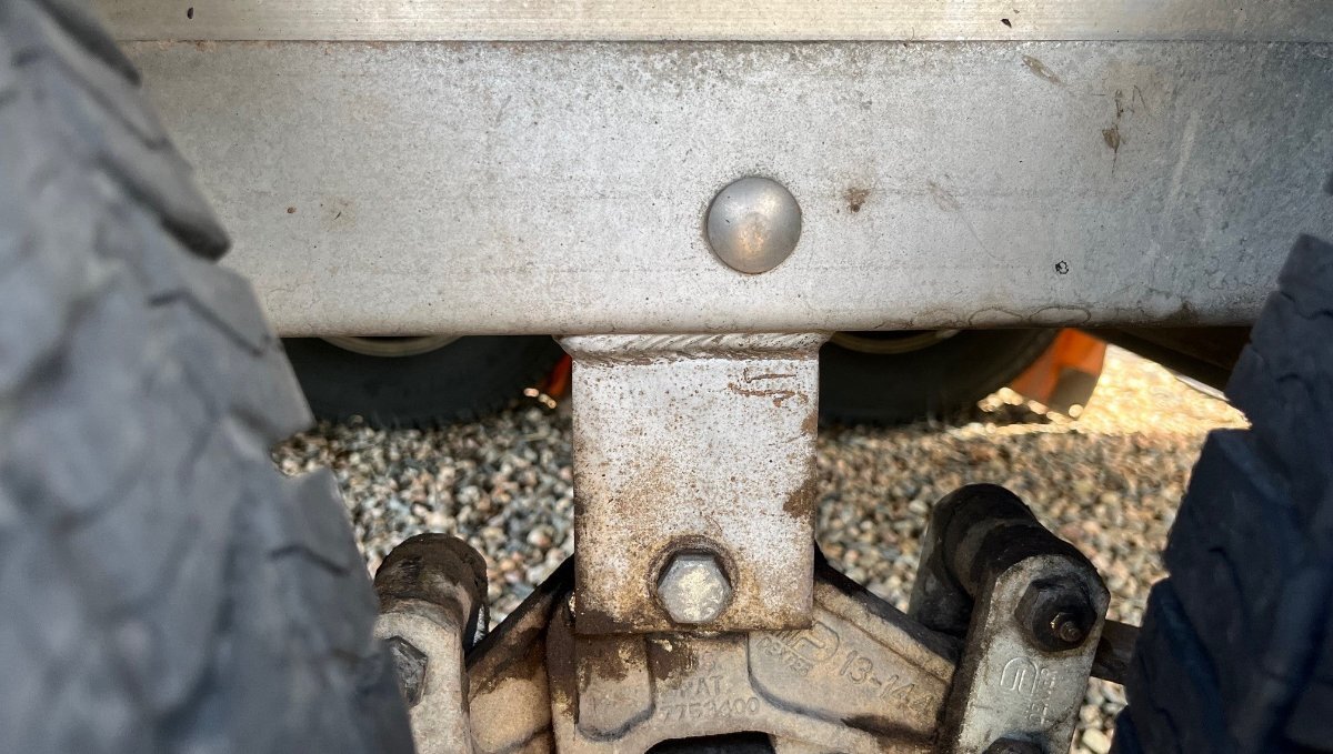
This truly upsets me for Chris, and it makes me doubly mad since it appears mine are the same way (now hulls 75, 110, 113 and others?). One mine, it's recessed 1/4 to 3/8" on the outside and I can feel the weld sticking out a good 1/8" on the backside! Neither picture above, @rideandfly nor @Wayfinder shows the inside weld past the steel frame. If ALL hulls from 75 to 113 had this as the specs, then it is NOT a defect. But if some are and some are not, then certainly a defect. I'll get a better picture, but these three pictures look completely different in many ways.
Trailer manufactures do not set specs for mounting distance of axles, in this case Dexter does. Were different axles used? Did Dexter change the spec?
As @Mountainman198 nicely stated, "have the narrower steel suspension frame replaced with one with a SC of 50.50”, thereby allowing newer axles to be fitted." If you're replacing axles anyway, this would be another hour of labor to bolt on new steel frames, not a manhour concern. However, today like everything else, these steel frames are another considerable expense added to an axle upgrade.
If I was to do this on our hull, I would determine the required length spec, take measurements, remove the steel frames and have a local welder replace the hangers. Or simply hold on to and service the original equipment as Chris has done.
-
2
-
-
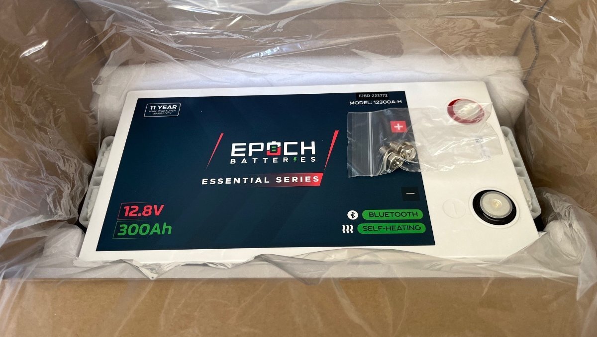
Santa came today, Christmas in July! Never received such beautiful batteries 600AH total. They came just before I started teaching my class today, got the FedEx guy to get them in my garage. On a break, I had to open one! Measures 13.12V in the box. Got to buy my new inverter ASAP. Love it!

-
8
-
 2
2
-
-
If you look at mine there is quite a dent in it, like a prior owner kept hitting their head in the same spot!
Cool you were able to chose fabric!
-
1
-
-
6 hours ago, katanapilot said:
You are absolutely correct. What I don't know is if Victron requires the two cable connection - to spread the load over the two input studs - or if a single 4/0 connection would be sufficient.
Doubling up cables can increase the overall amperage in the connection. They have tables for that online. The dual terminals in the Victron multiplus can be used in this way, but as evidenced above, one 4/1 is already overkill.
I'm going to use the second post to connect 12VDC +/- to the Oliver 12VDC fuse panel. The OEM wiring has both connected directly to the batteries. This will clean up the battery bay, using the built-in Victron bus vs. adding another.
The true reason for the dual terminal is that Victron products are designed to be installed in multiples. Use of the second terminal can daisy-chain multiple inverters side-by-side.
-
1
-
-
18 hours ago, SeaDawg said:
If you never hit your head, let it go...
It's funny that in a year of use, 30+ days camping, and so many ins and outs doing repairs and mods, at 6'2" I never hit my head because of the way I carefully enter and exit. This weekend doing my fridge fan mod, I banged it pretty good!
You can see in the picture; it's not even shaped squarely anymore. It's a big 3x3" wide, old foam on old plywood, not worth the time to reupholster. I'm thinking something semi-round and thinner like 2x2" wide, a cushion but not something upholstered. Still wondering if anybody had else replaced theirs with something else?
-
9 hours ago, jd1923 said:
I believe we have two generations of OTT hulls and Xantrex products, mine being a 2016 and yours a 2020.
Mine is an inverter and it appears @katanapilot has a Xantrex 2KW inverter/charger.
-
1
-
-
Worked on this Saturday afternoon and an hour today to button it up!
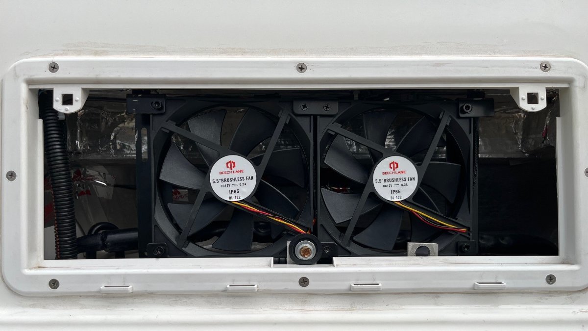
I started working it like some installs here, and I was able to poke a steel fish-tape from the back of the pantry down and right through the foil-wrapped Styrofoam to the exterior fridge opening. Then I thought about routing the wires down and realized if I fish the wires down about 20" further back at the rear of the fridge, the wires could go straight down to the bottom in one line. The bottom of the close side of the fridge is where the LP burner is located, and you would have to divert your wiring somewhere.
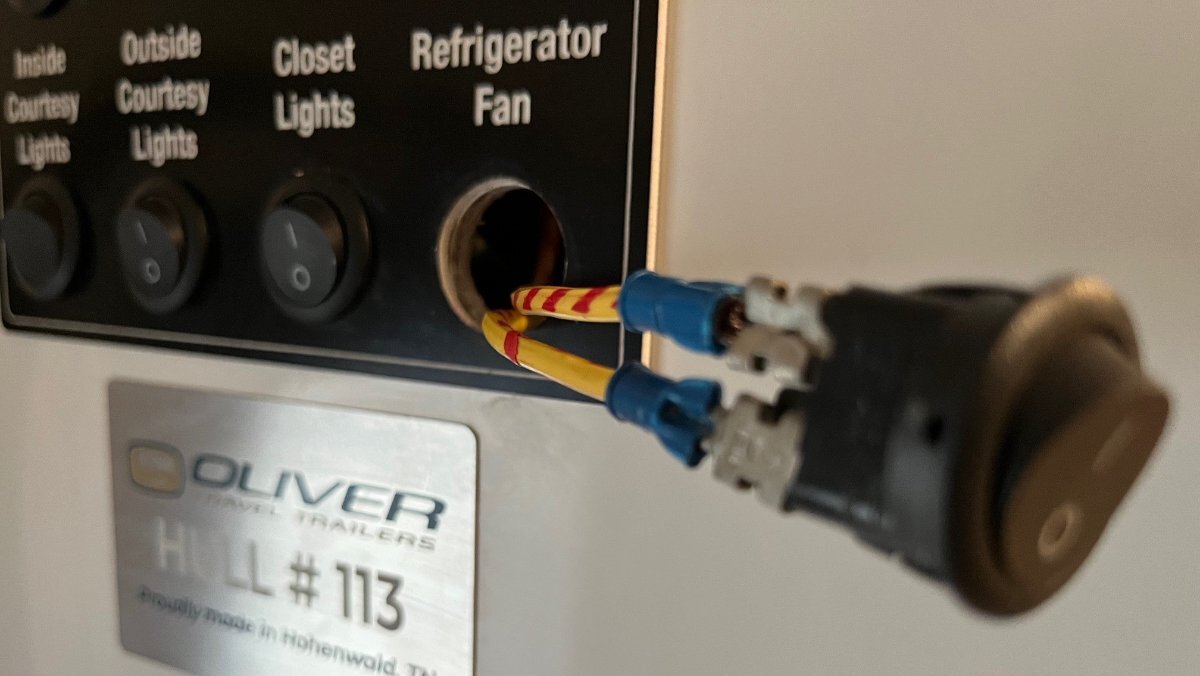
The whole Beech Lane wire harness and a pair of switch wires (yellow/stripped red) fished through after cutting the opening shown with a rounded chisel and a few tugs.
The temperature sensor taped to the upper incline.
Switch legs run up and the across the back of the upper kitchen cabinet. Yes, removing the 110V outlet makes fishing easier. One leg is connected to the ground at the exterior base of the fridge and the other to the fan ground. I taped this switch prior to reinserting.
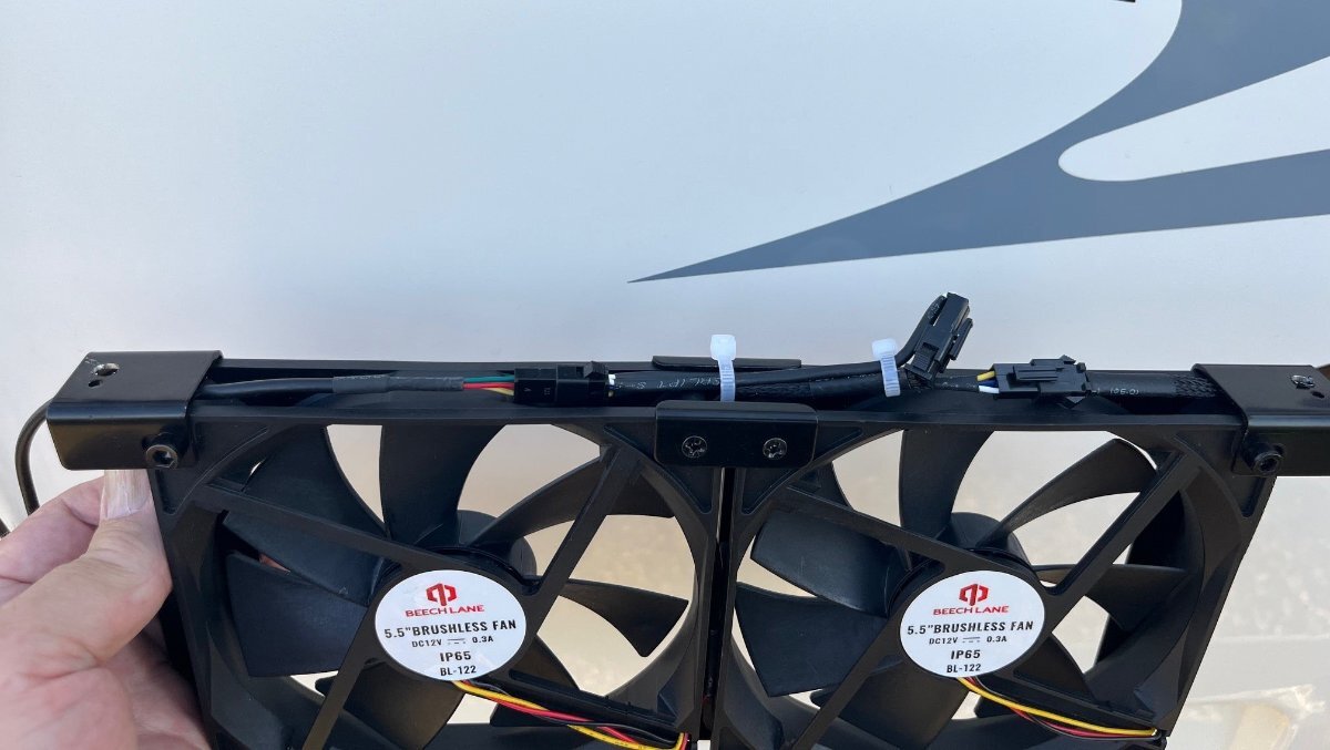
The fan comes with clips to mount to the exterior vent cover (not a great idea for several reasons). I modified the fan assembly so that the cabling would be captured by the frame and tied down. Notice the screw holes left and right drilled larger for mounting to the ceiling of the vent opening.
The fan was first rubber-mounted with one screw bottom center in place of a small screw that held the two fans together. Drilled pilot holes and screwed up in each top corner. Notice the 1/2" automotive wire loom LHS that holds the harness and switch wiring.
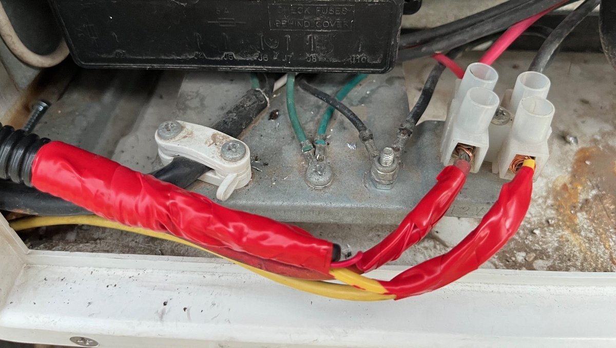
Bottom vent opening showing the junction B+/B- source, with harness +/- connected here and taped.
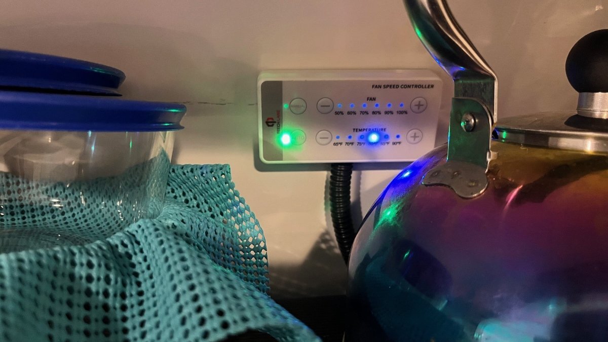
Control panel in upper kitchen cabinet, mounted with 3M VHB. No interior drilling harness just hides behind rubber floormat. Can reach in nicely or move the tea kettle if you must. Everything tested positively, the ON/OFF switch on the OTT light panel, manual mode with fan speed adjustments, and auto mode temp settings matched my RUUVi sensor readings. It was hot in the afternoon and then a front came through and dropped temps 20 degrees. The fan turned itself off and when I set temp two clicks lower it resumed.
Thanks @Ronbrink for your help! The Beech Lane product is great, works well, fits the opening fully, and is quiet even on 100%. When it's running, and you're inside with the entrance door shut, you will not hear it. If you do not have the OEM built-in ON/OFF switch, don't worry you should not need one. My panel has one, so I felt obligated to make it function again. No complaints from this old installer! 🤣
-
3
-
1
-
-
11 hours ago, katanapilot said:
I have no GFCI receptacles except for the one on the Xantrex. Obviously a lot of differences between hulls.
Same here and that means there is no GFCI unless running the inverter. It's also odd that Mike with hull 308 has a GFCI outlet and your hull 628 does not, like my old hull 113 does not. Why?
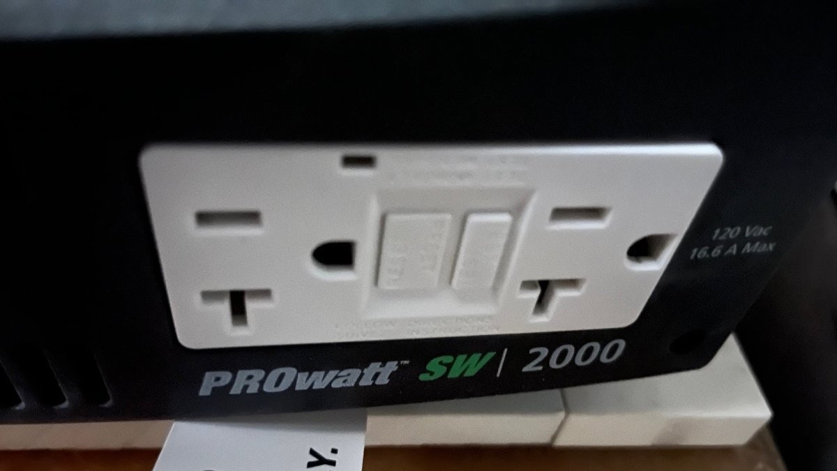
I believe we have two generations of OTT hulls and Xantrex products, mine being a 2016 and yours a 2020. My 2KW Xantrex only has 6 possible connections. On the backside with the fans, there are 3 DC connections, B+ an and B- connected by 4/1 AWG cable directly to the batteries and a 6AWG(?) ground that connects to the yellow ground bus under the rear dinette seat. The front side does have a dual GFCI outlet, rated 120 VAC 16.6A, the monitor cable and LCD screen
The older Xantrex in our hull does not have what you wrote "20 amp feed to the AC input of the Xantrex." Do you have the more modern look Xantrex, fully rectangular, squared edges painted gray? Or does yours look like mine, rounded edges metal looking black vinyl coated? I believe you have the newer generation Xantrex.
BTW, who cares! I'm ripping mine out end of July, the Xantrex, the Xantrex ATS, the funky little electrical box stuck in the corner that connects inverter supply to most 120V circuits, all the but the A/C. I will show my work here and looking forward to seeing yours.
All that matters, is... After all the old is removed, you connect the Victron MP to the batteries in the same way and to the ground bus. You connect shore power from the PD5100 ATS to the AC input and connect the 50A L1 output circuit to the entire Oliver 30A AC panel. This time including the 20A breaker for the air conditioner that was previously bypassed. Can't wait!
Pictures to follow:
1) GFCI close-up on inverter
2) PROwatt SW, with junction box above and inverter below
3) Rear Dinette seat with PD5100, self-installed EMS, Xantrex 2KW inverter and self-installed KISAE TS20 switch for running A/C on inverter.
-
1
-
-
3 hours ago, katanapilot said:
Unless yours is different from mine, all GFCI protection came from the GFCI outlet on the Xantrex receptacle.
I have thought there is no GFCI protection on the Oliver. That's the way it appears to me. Given the Xantrex has GFCI outlet(s), you must realize that when on shore power that outlet is not utilized so you have no GFCI protection.
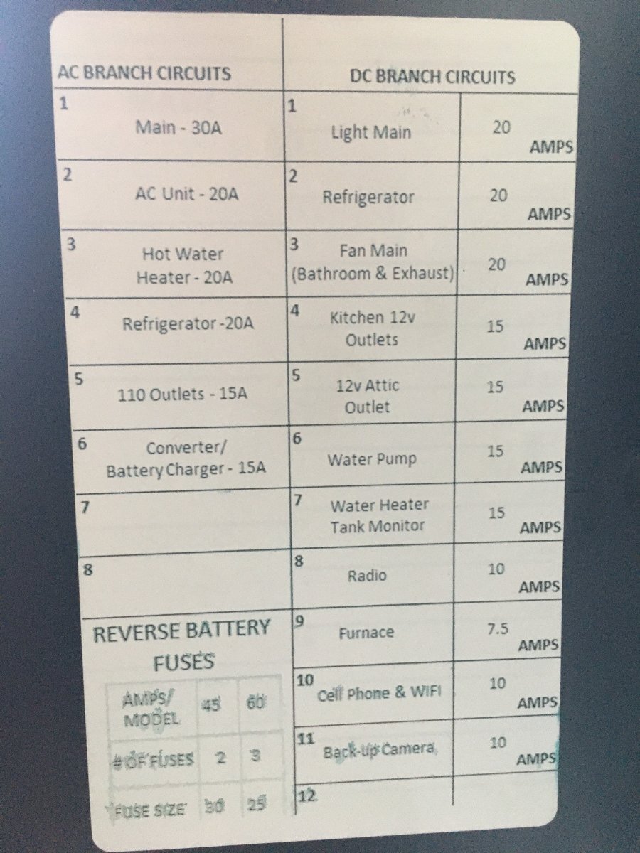
Residential code (don't know for RVs) requires GFCI protection for bathroom and exterior outlets, for where water is present. You could replace the 15A breaker for "110 Outlets" with a GFCI breaker or replace the first outlet in line with a GFCI outlet.
It's crazy that OTT strings all the 110 outlets including one for the microwave. There is an independent breaker for the fridge. All they needed is an extra breaker for the microwave and a parallel cable run to the fridge run. Not sure if a 15A GFCI breaker can handle the microwave and still be responsive to a fault at another outlet. When the microwave is running, there is only about 5A available.
We have a 15A GFCI breaker at home. The builder wired 5 outlets in 3 bathrooms plus two exterior outlets on the deck. We added a flat grill on our deck. When the grill is running and Chris starts her blow dryer, we instantly lose power to all 7 outlets. Sometimes it blows without two heating appliances. It's 45 years old as is our house. I should buy a modern 20A GFCI thinking the cable AWG is adequate.
-
Anybody change this item with something better, something thinner and more aesthetically pleasing? We are replacing our dinette cushions too, so this would be the last piece of this old ugly/bland fabric in our Oliver. Any ideas?
-
3 hours ago, rideadeuce said:
At that point, I would just use the separate HEAT ONLY and COOL ONLY modes.
Thanks Mike, I had not run across the manual. Reading this makes more sense. Not sure when I questioned Kevin, he didn't inform me that I could use COOL vs. AUTO modes for what I asked. The fan will still run all night. My fix for that is the timer or the remote would be in arms reach, powered off when needed.
Now that I have the furnace duct mod, with bedside duct capped off, I believe I would likely rarely use the heat pump which would blow warm air over the beds and not front or in the bathroom. Many voice they like the heat pump option. I'd give it a try to see but would likely prefer the warm bathroom and heat aimed on the floor vs. up in our face.
For those of us who camp more often on inverter than connected to shore power, when A/C the sun is out and there is some positive AH offset. When you need heat, most of the time it's dark outside using considerable AH without solar replenishment and we carry 60 gallons of efficient LP.
-
1
-
-
2 hours ago, rideadeuce said:
Power assist as I understand it and used so far is helpful when connected to shore power not boon docking or traveling.
Given the PD5100 ATS, the MP inverter would treat a small generator as a form of under-powered shore power and the Power Assist would kick in, adding required power.
But yes, adding the SoftStart lowers the initial surge to allow running on a household 15A circuit without tripping a breaker.
The extra features of the MP2, I will likely not use. It is the dimensions and +1AH more on idle is 24AH per day. Still what fits best will make the decision.
Next week I will open all street-side basement panels, measure, plan, decide and purchase.
Given the MP2 is better, why can I buy one for $997 and the MP is $1,169, from authorized dealers. Another point for the MP2!
-
2
-
-
12 hours ago, katanapilot said:
Our Victron MPII just arrived, along with all of the other Victron equipment. Install to commence next week.
Why MPII vs. original Multiplus? What other Victron HW? Thanks
-
29 minutes ago, rich.dev said:
All Xantrex Inverter/Chargers incorporate an automatic transfer switch...
That's a good way of wording it. My 2WK Xantrex is inverter only (no charger and no ATS). All it does is supply 120V AC to two plug-in outlets. The switching in this system occurs in the PROwatt SW, an external switch.
-
1
-
-
2 hours ago, katanapilot said:
I have to ask why so many of you are using 4/0 cable? My Oliver came with 2/0. Victron specifies 1/0 for the feed to the 3000va Multiplus 2 inverter for lengths less than 5 meters and 2/0 for 5 to 10 meters.
Just concerned that I’m misunderstanding the wire ampacity tables.
You're not misunderstanding. Without doing the math myself, Victron's numbers appear correct. Over-engineering is common in DIY efforts and going to heavier gauge cable doesn't hurt, just costs more money.
OTT installed 4/0 in our hull too. The length of the run, from the batteries to our 2KW inverter under the rear dinette seat is about 1m or 4 ft at most. The Oliver is over-engineered in many ways, and we appreciate that. The cost difference of 2-3m of 4/0 over 1/0 cable, at wholesale to a manufacture, is not much and they are being over-safe for a few bucks.
When I go to install a DC-to-DC charger, two cables the length of TV and TT, likely over 25m, I will buy the gauge required and nothing more due to the retail cost of copper today!
-
1
-
1
-


Victron Multiplus and MPII Feedback Request
in Ollie Modifications
Posted
Just decided on the MP2 for the sole reason is its dimensions. Wow, the 2x120V version is amazing for those with 50A RV systems but we only need a single 120VAC input and output. There are grid capabilities in the MP2 for home use that doesn't matter for RV usage.
The original MP is actually smaller in volume, 2 LBS lighter, but the 8.6" depth vs. 6" is the real difference. Also, the MP has an aluminum casing vs. thin steel which may be better in some climates.
Under the streetside bed as Mike @rideadeuce installed will be my choice too. I will figure out a footing and strapping for the MP2 without the heavy HDPE and epoxy. The MP2 is 23" long, almost 9" longer but there is a lot of length under the bed. I just added the Beech Lane dual fan for fridge cooling and if needed this would be a great addition to add it the wall to the rear going to the trunk area.
I did not hear from any of the 3 or more Oliver owners with in an installed Multiplus re inverter or fan noise. Sure hope it is not noisy as it will be under my bed!
Hoping the MP2 has dual battery terminals. It looks like Mikes does in the pics. I see pics from Victron, some show single screw terminal and most show a built-in terminal/bus with dual screw terminals. I have no interest in Victron Lynx buses or any additional bus for that matter. The Oliver already has DC buses installed. One terminal on the MP2 will of course connect directly to the batteries and I will use the second terminal to run 12VDC to the Oliver buses. There will only be the 4/0 cables in the battery bay.
Still working on best price and will place an order Monday latest. I'm getting the Victron VE.Bus Smart dongle to program the MP2 and read status via the Victron app. This would be in place of any wall-mounted display accessories. I read I may also need a Victron Current Transformer for the Power Assist to work effectively. These are relatively inexpensive parts.
Yesterday, I removed the lead-acid batteries. Today I'm pulling the 2KW Xantrex inverter, the Xantrex ATS and junction box. This is a complete OTT installed working system if anybody needs one. Put the LA batteries on Craigs, who knows. Will oen up the EMS and the 120V AC panel to ready the wiring. Building the MP2 platform will take some thinking! 😂