Townesw
-
Posts
562 -
Joined
-
Last visited
-
Days Won
22
Everything posted by Townesw
-
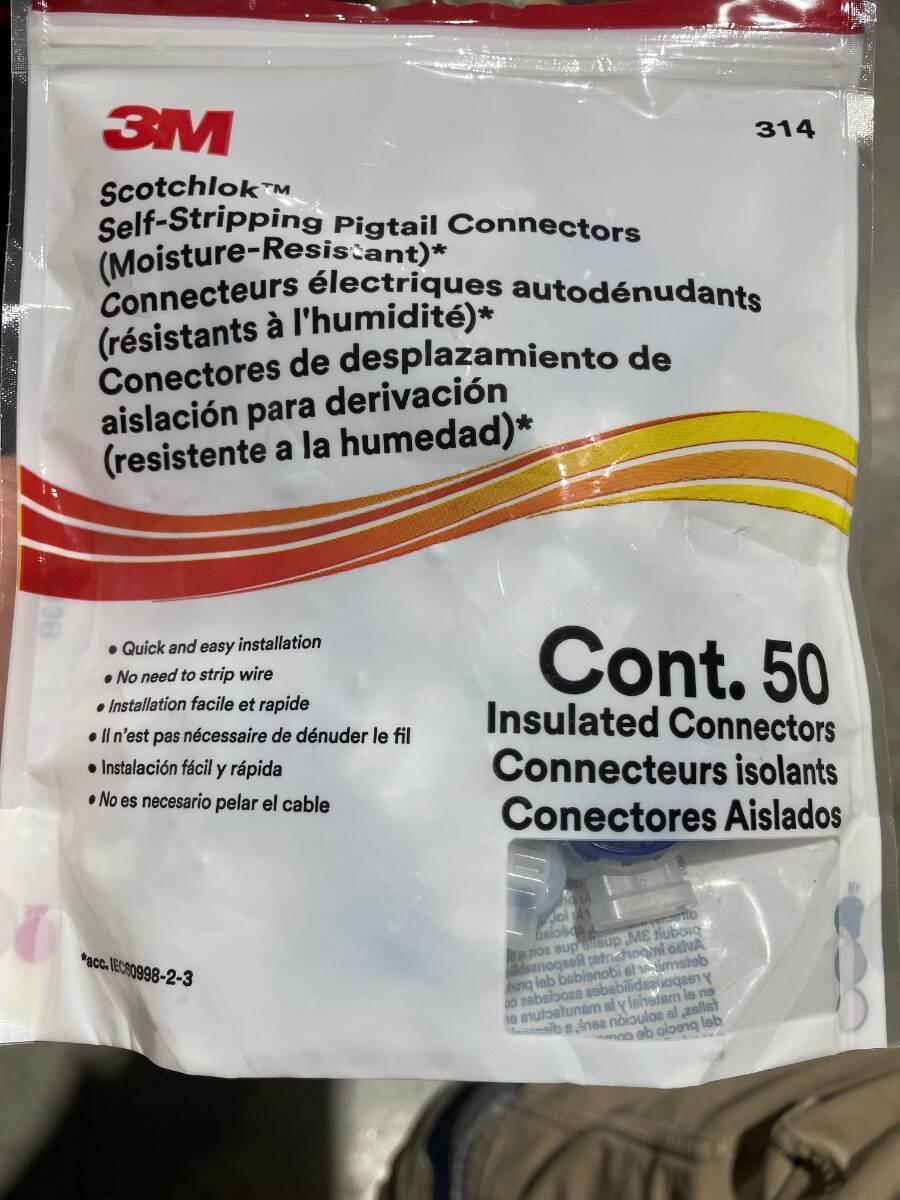
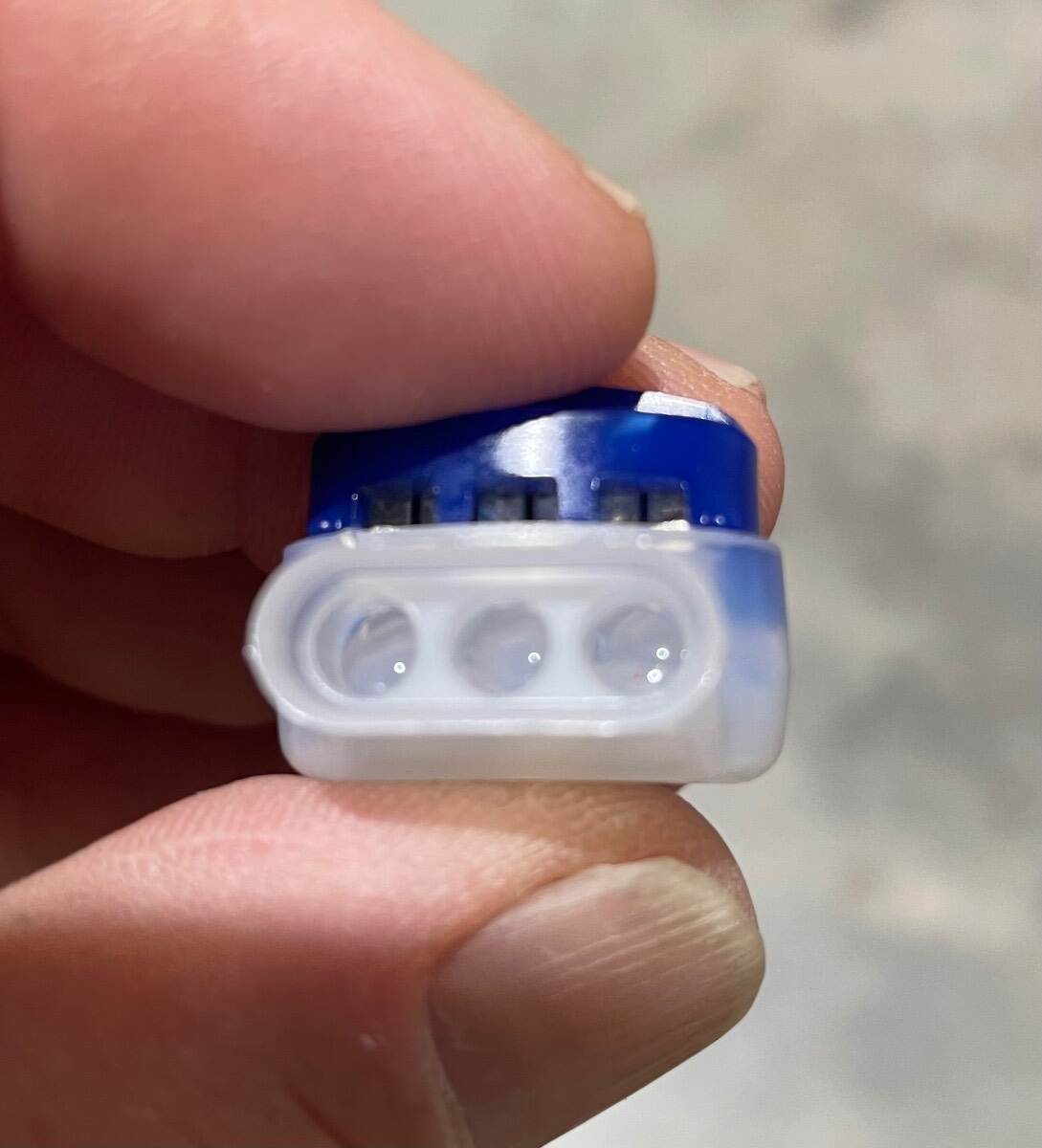
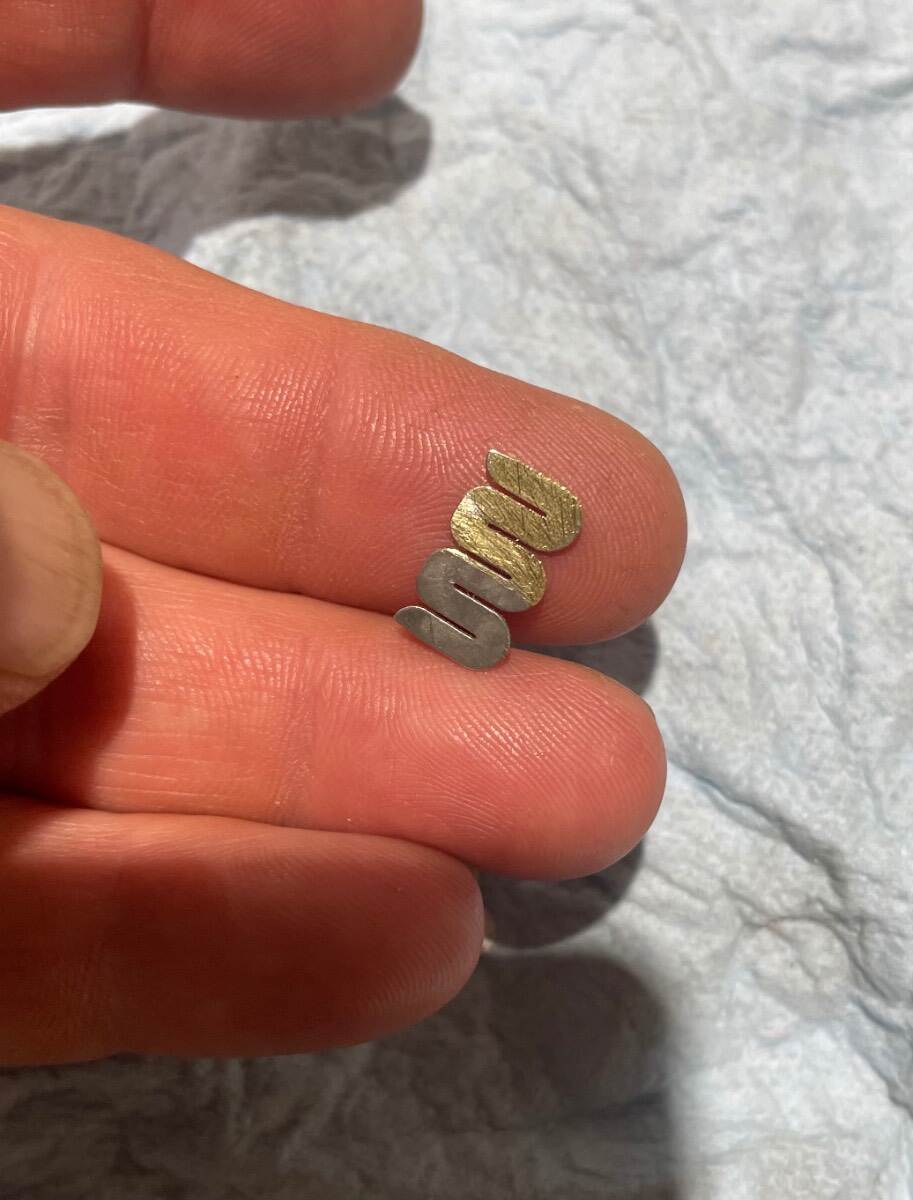
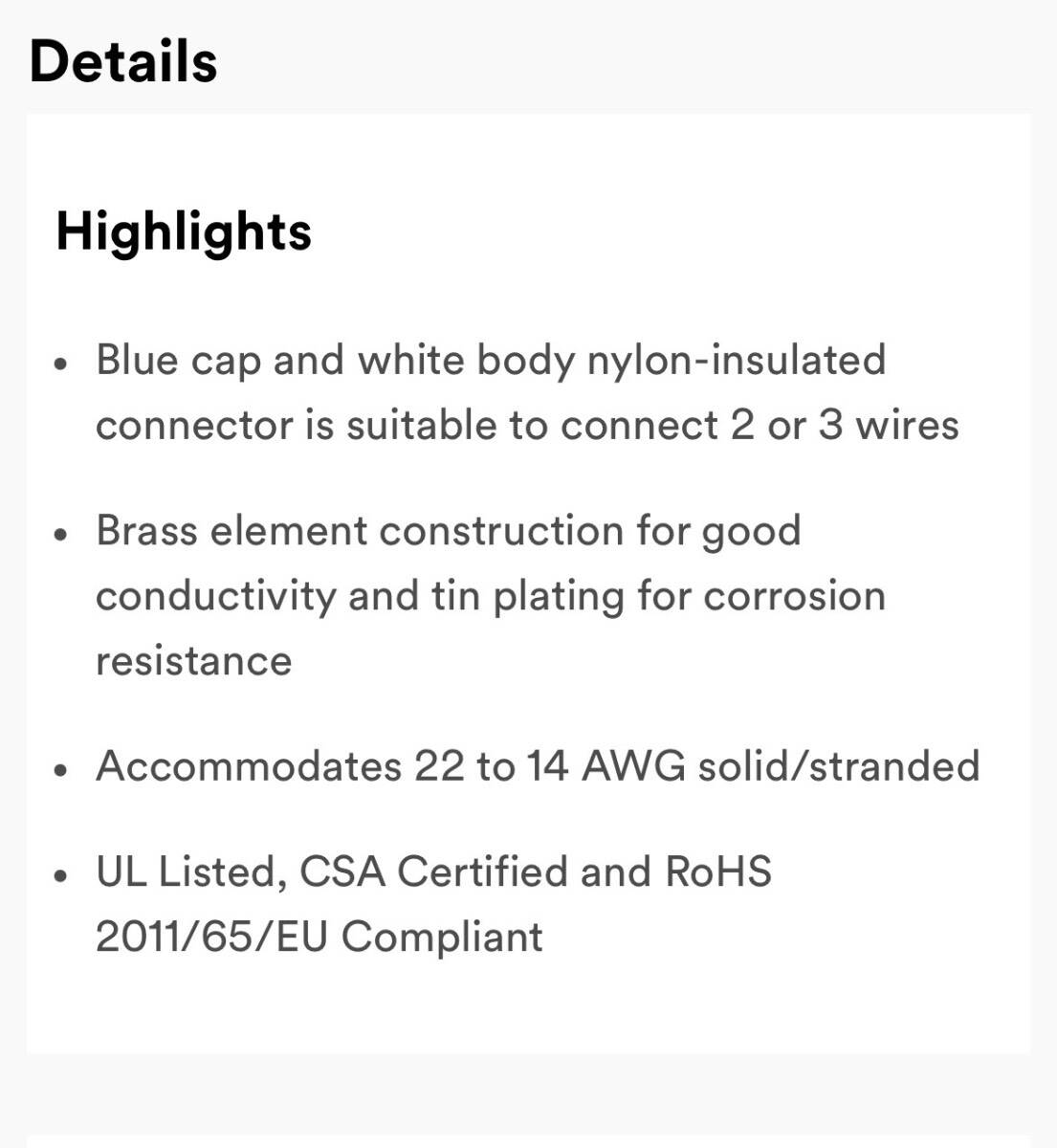
I used these to wire lights on a utility trailer. https://www.3m.com/3M/en_US/p/d/b10128463/ What would be wrong with using these instead of heat shrink butt splice connectors to make brake wire connections under the trailer? Notice that they are IDC (Insulation Displacing Connectors) and that they are water resistant (they contain what I think is dielectric grease). Notice also that they connect up to 3 wires, as in the situation encountered on the street side connections. I don’t care for the typical IDC connector (usually blue) with the fold over and snap down piece, but these are much better and they are made in the USA by 3M. EDITTED TO ADD: According to the 3M website the conductor is tinned brass. I took one apart and used a file to remove the tin. The blade is brass, or at least some kind of yellow metal. Bill

-

Looking for a part of a 2019 wiring diagram
Townesw replied to rferg800's topic in Ollie Modifications
Heck I just realized that mine is a 2018 trailer. I apologize for my mistake. Anyway, does this help any? Bill
-
Looking for a part of a 2019 wiring diagram
Townesw replied to rferg800's topic in Ollie Modifications
I have 2019 (correction 2018🤪) hull 313. What drawing do you want? None of the electrical schematics in my manual show either of the shore power outlets. -
Late February 2022 until Mid October 2025 - 3 years 8 months no trips. Bill
-
Please don’t respond with long winded dissertations, conjectures, theories, thoughts, wishes, guesses, etc., etc., etc. As Detective Joe Friday said "All we want are the facts, ma’am” Simply stated : What axles, springs, shocks, EZ Flex Equalizers, shackles and bolts are being installed on Current Production Legacy Elite II trailers being built right now? Also the same for the Apex model? Include part numbers and pictures if you have them. Bill
-
Look at using King StarBoard for a better waterproof mounting board. It can be cut and shaped using regular woodworking tools. I get mine from McMaster Carr but there are less expensive places to get it. A shipment from McMaster Carr usually arrives the next day depending on where you are. I think I have ordered some from TAP Plastics https://www.tapplastics.com/product/plastics/cut_to_size_plastic/king_starboard/526?gad_source=1&gad_campaignid=21137328659&gbraid=0AAAAAD_hg_I8XrL-S3Ima0ZSWbIsffsZk&gclid=CjwKCAjwmdLSBhANEiwAkREMN3hswfK8uVUE38-cgCmjAoCwEzeXRTPZLhht1xFJJ1A8-NIIMHzIkhoC2_gQAvD_BwE I don’t know why that link has to have so much gibberish in it. Bill
-
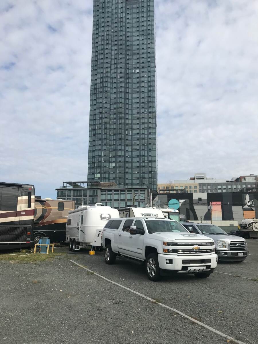
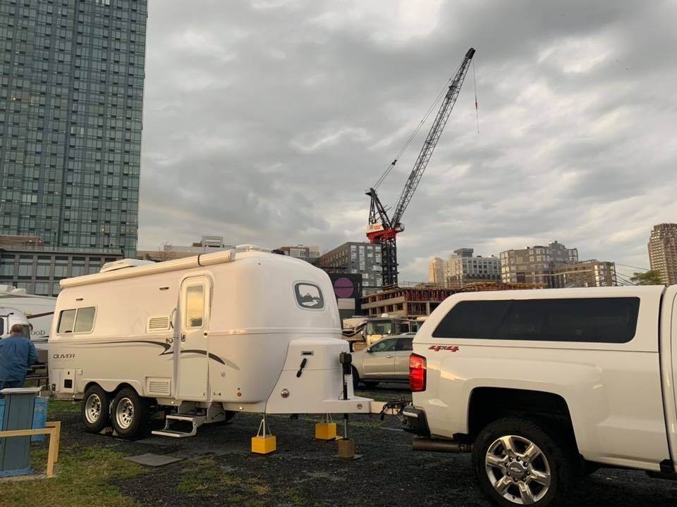
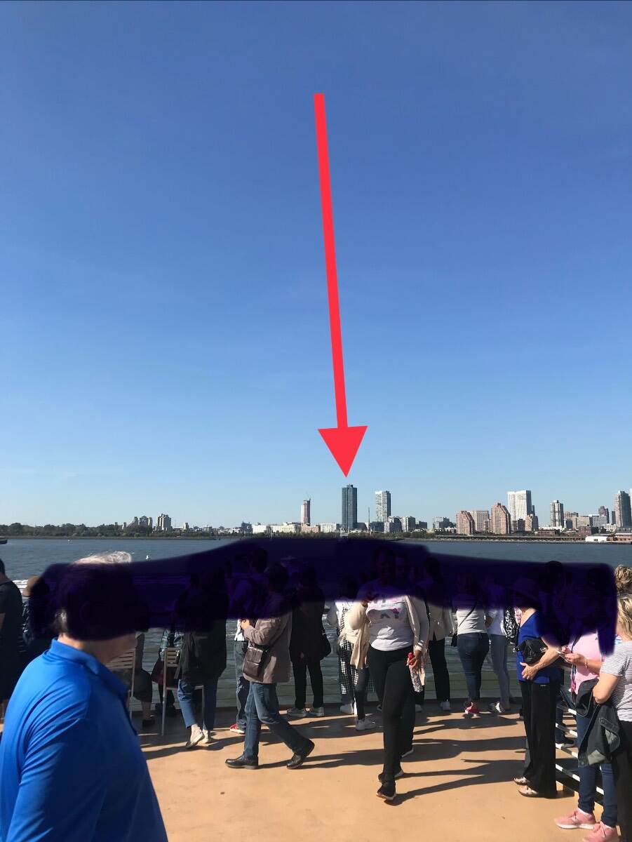
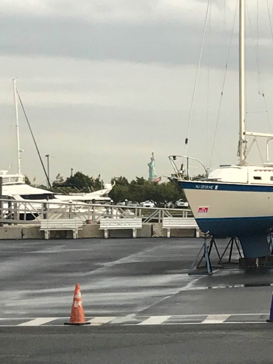
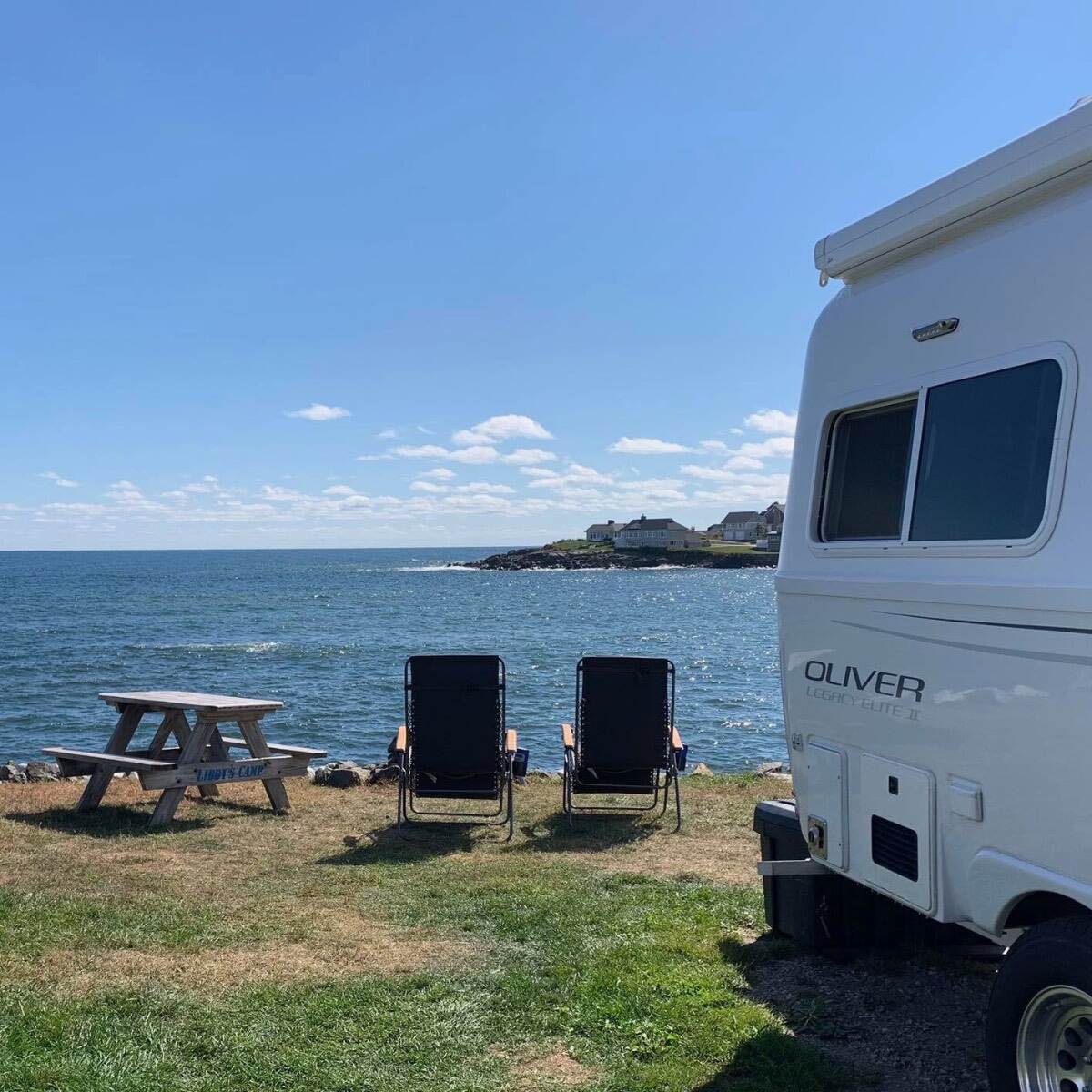
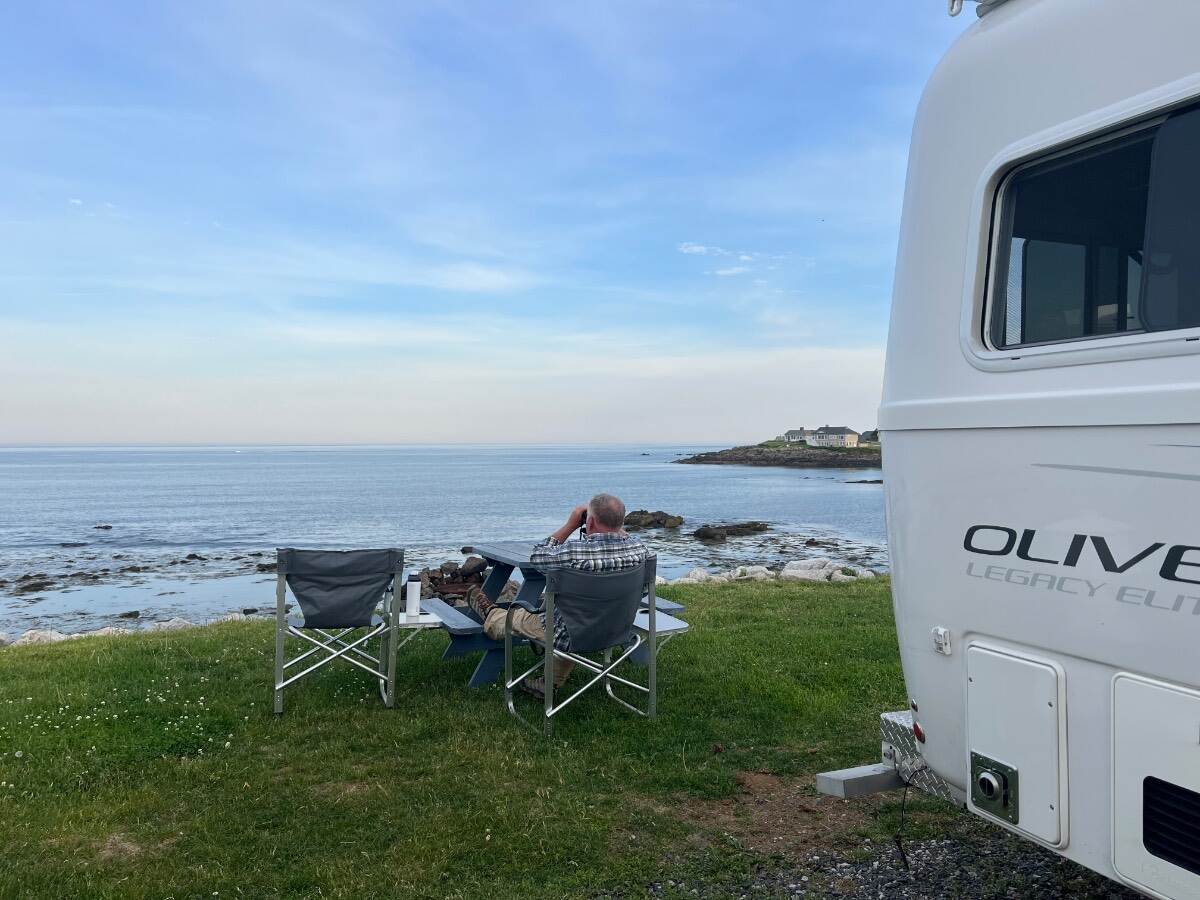
Over the past few days I’ve looked through all 39 pages of this thread. Very pretty pictures of “Where Is Ollie”. I have pictures of a not-so-pretty location. During late September, 2019 our Oliver was here for a few days We were parked near the base of this building A hint as to the location A screenshot from the campground’s website At the next campground after my one-and-only venture into NYC our Oliver was parked here. A much better looking location. September 30, 2019. And then again in June of 2026. Libby’s Oceanside Camp, York, ME. One of our favorite campgrounds. Bill
-
Be sure to unplug the 7 pin connector from the tow vehicle when testing the breakaway switch. When the pin in the breakaway switch is pulled 12v power from the trailer’s batteries can back feed into and cause damage to the trailer brake controller on the tow vehicle. Bill
-
I would like to see pictures of the bathroom door being installed in current production models. Can someone with the newer style door please post a few pictures? If you can find a manufacturer label please post a picture of that also. Bill
- 1 reply
-
- 1
-

-
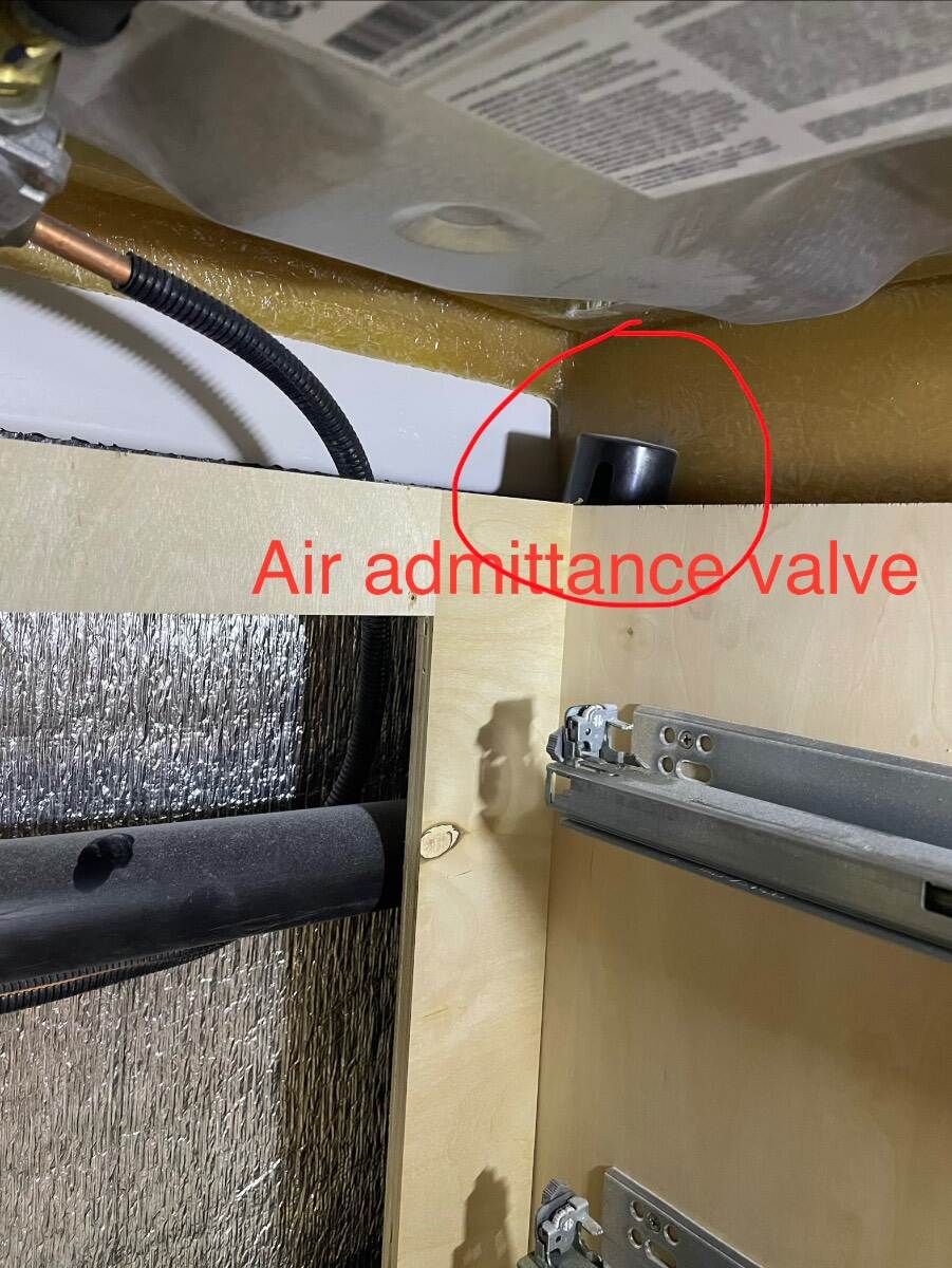
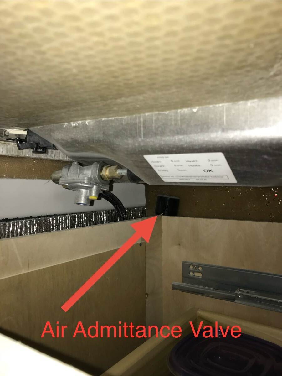
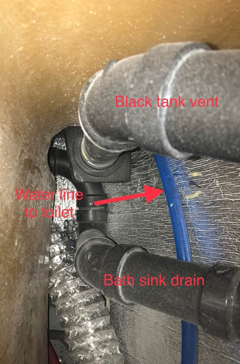
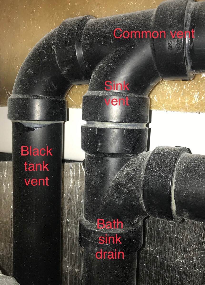
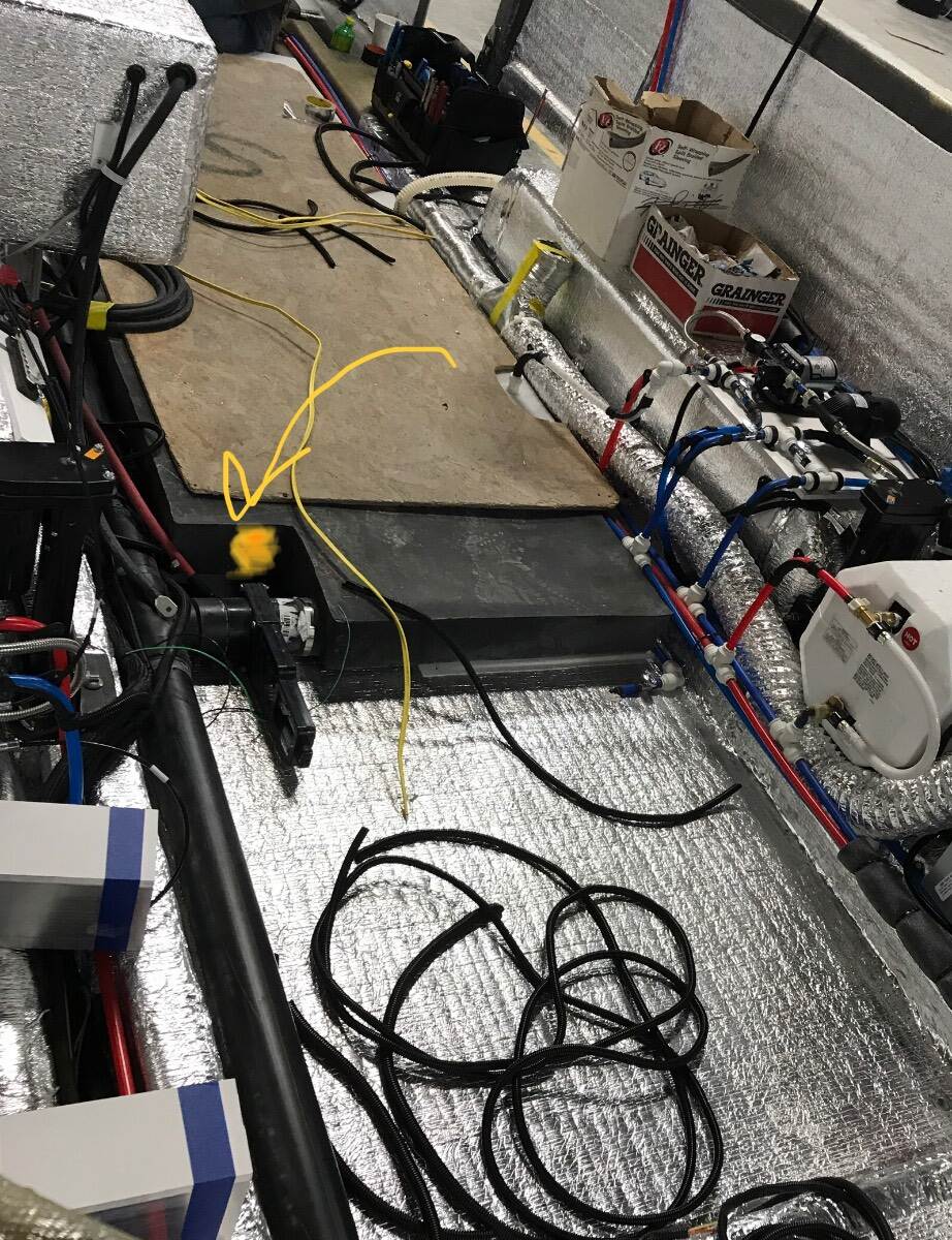
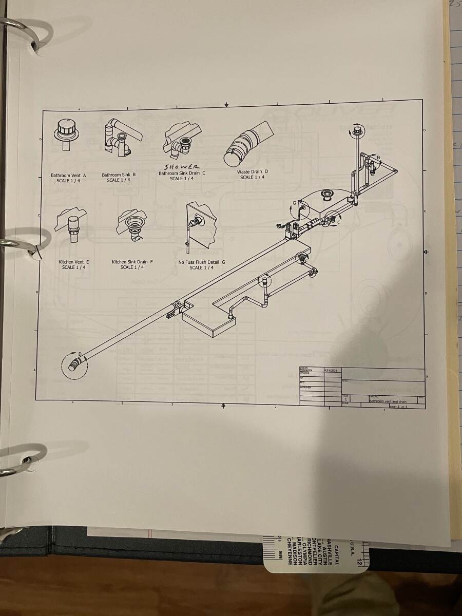
That roof vent vents the black tank all the time and the gray tank only when the shower valve is open. There is an AAV - air admittance valve - under the kitchen counter in the back right corner of the kitchen drawers that should allow air into the gray tank when draining even if the shower valve is closed once the water level drops below the place where the kitchen sink drain enters the gray tank. The bath sink drain and shower drain flow through the open shower valve to the gray tank. Bill
-
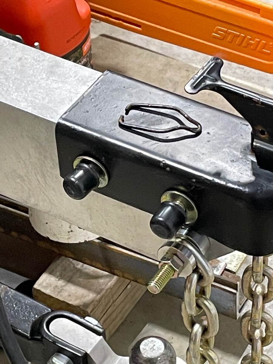
Upgrading from a Bulldog 2” coupler to 2 5/16 BD coupler
Townesw replied to Patriot's topic in Ollie Modifications
Those of you who use a lock in the lever as a method of securing your hitch should consider the Collar Lock. The wire bail between the lever and the sliding collar that secures the clam shell is easily removed without tools and the sliding collar can be pulled back by hand. Bill
-
Look under street side bunk. Make sure valve is open all of the way when handle is pulled. Also if you’re going to fill it lay a water hose in the shower pan (but watch it REAL close) and really raise the nose so you are washing the bottom of the tank. Fill tank until water stops draining in shower pan. Be sure to quickly turn water off. Open the valve and let it rush out. Do it a few times. Watch what comes out if you can. You know that white snot that grows in HVAC condensate pans and lines? I think similar stuff grows in gray tanks. I think #1455 has sat unused and you have a build up in your tank. I think people set these trailers up level, hook up to the sewer and open the drain and let the water out as it is filled. This lets solids settle on the tank floors. We were told to keep the drains closed and only dump when the tanks were filled so that solids could be flushed out. We always dump black first. Then we use the flush inlet and fill and drain the black tank 3,4,5 times until I don’t see anymore floaters (we don’t put paper in our black tank) in the clear elbow at the sewer connection. Then I open the gray tank and let it drain while I do something else. After a few minutes the gray tank level is 0. Since I got that gunk out of my gray tank I haven’t had any problems. It will still drain slow but I eventually get to 0%.
-
My gray tank was draining really slow one time. I filled it then drove around and went home and backed it down a slope and dumped. The water came out with force and brought out a nasty looking slime. Since then we have added dawn dish washing soap and traveled with some water in the gray tank. I try to dump the gray soon after getting home while backed down a slope so as to get really good flow. It still drains slow due to the size and layout of the tank but it was much better after I got the algae (?) out of it.
-
Hello Aidan. The gray tank will drain quicker if the front of the trailer is raised a little. Raising the curb side a little near the end of the process also helps. The gray tank is long, narrow, and thin and the drain valve is on the left side rear corner of the tank. The gray tank level sensor on hull 313 is located where the yellow blotch is shown on the picture below. My tank level could show 0% and still have water in the rear of the tank if the nose is too high. Bill
-
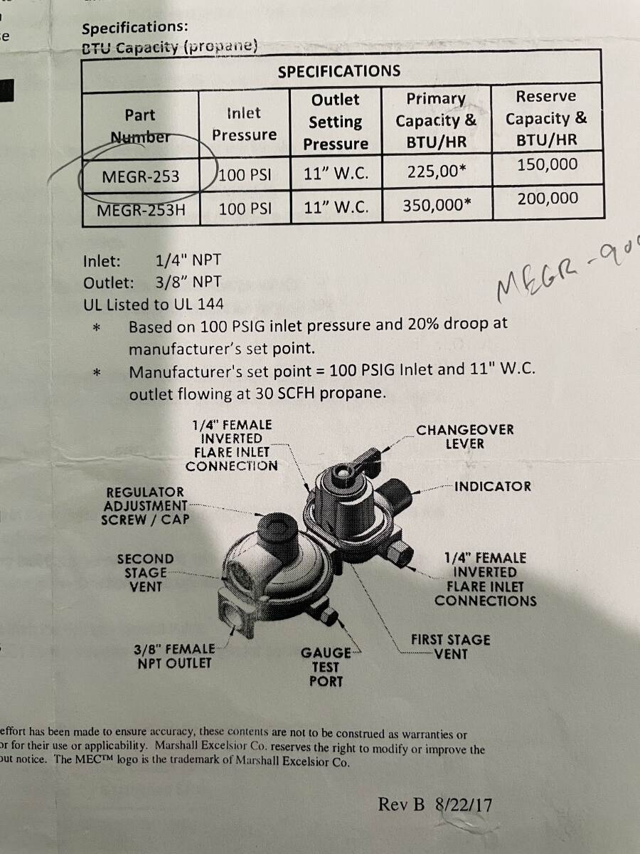
@Boudicca908Thank you. If you order the MEGR 253 I think it comes with straight inverted flare fittings installed in the inlet connections. You should be able to connect your current pigtails to these fittings if you don’t want to convert to the 90 degree inlet fittings. You will still need pipe sealant or tape to attach the 3/8 inch fitting on the supply hose from the trailer to the outlet connection on the bottom of the regulator. If you get teflon tape be sure it’s rated for use on propane and natural gas. It will probably be yellow. Most Teflon tape you see is for water and air. Before applying new sealant or tape be sure to clean all of the old sealant or tape off of any reused male or female pipe threads and don’t let any of it fall into the regulator or hoses. If using teflon tape start the tape just shy of the end of the male threads so it doesn’t obstruct the opening and wrap it in the same direction that you will be turning the item with the female threads. I’m afraid that my instructions seem intimidating but this really is an easy project. Bill
-
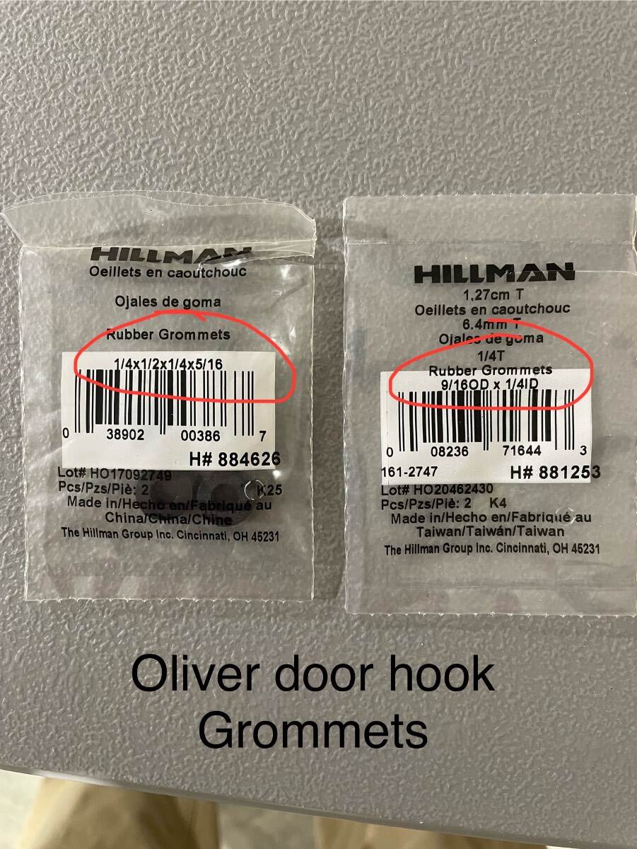
These came from the Hillman drawers at Lowe’s. I can’t remember why I bought 2 sizes other than I found that 2 sizes would fit so I bought both. One may have rounded edges and the other square edges. Bill
-
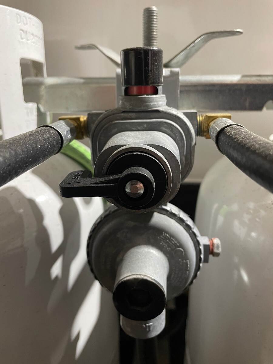
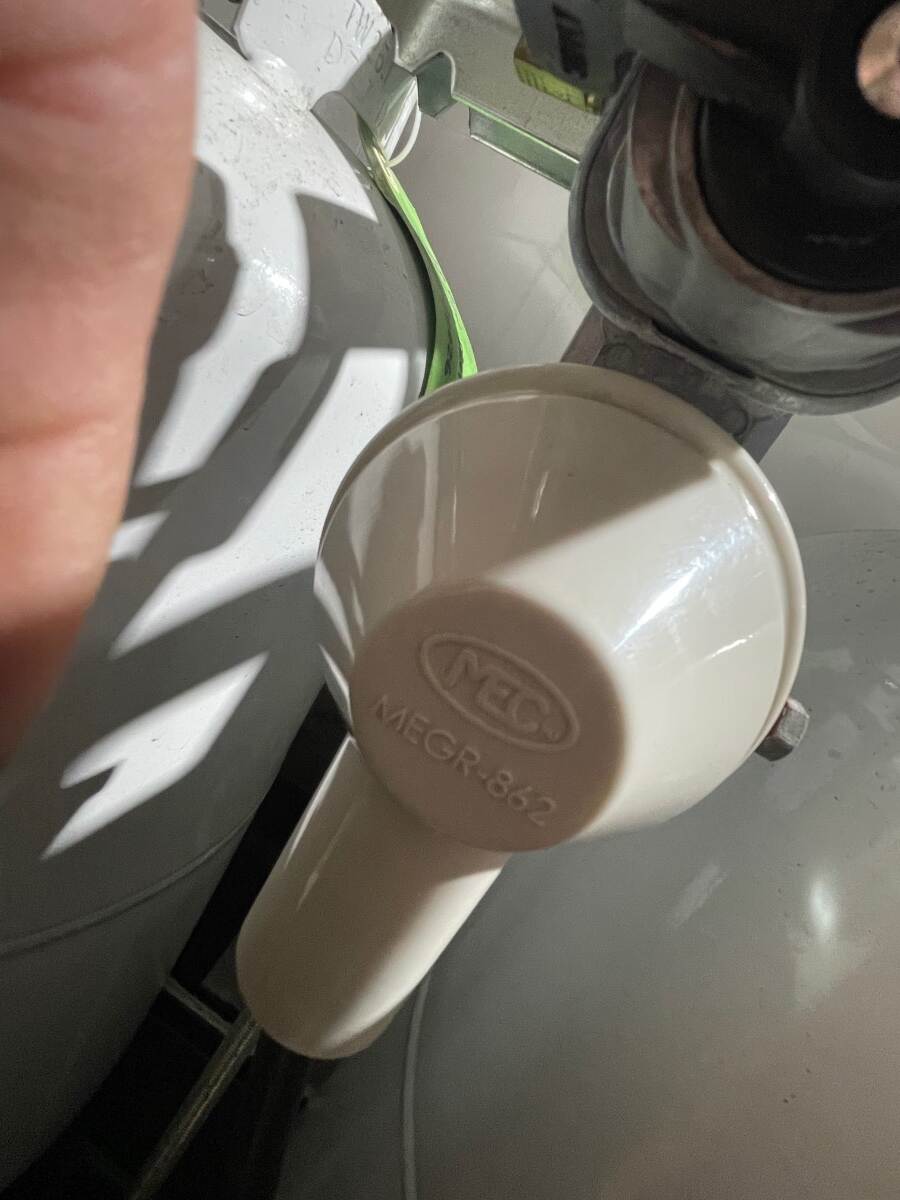
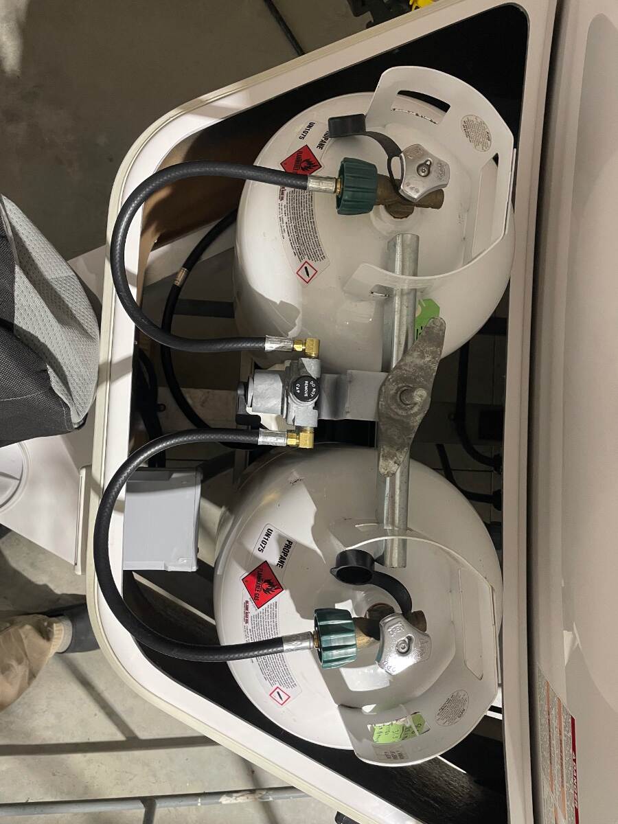
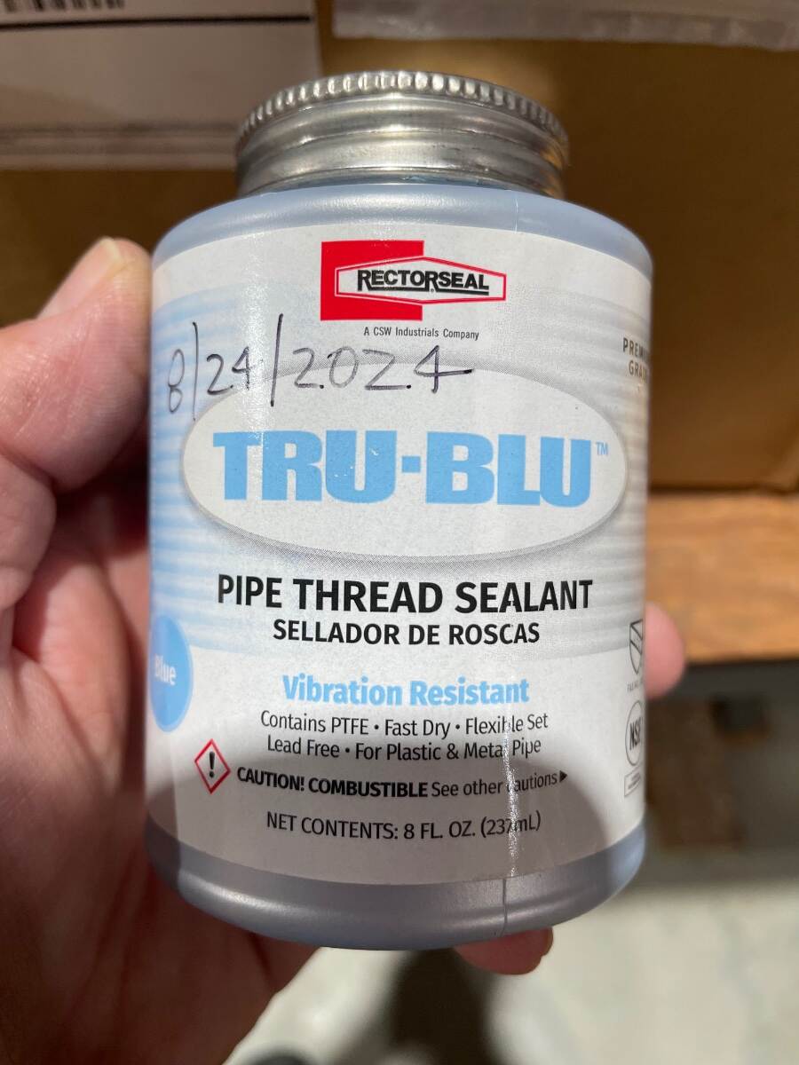
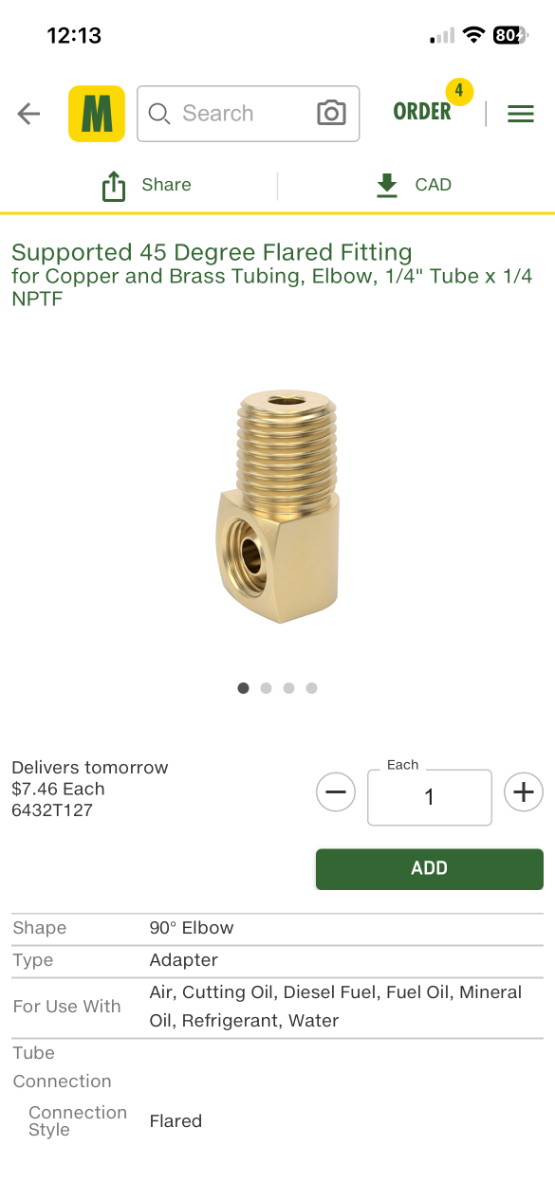
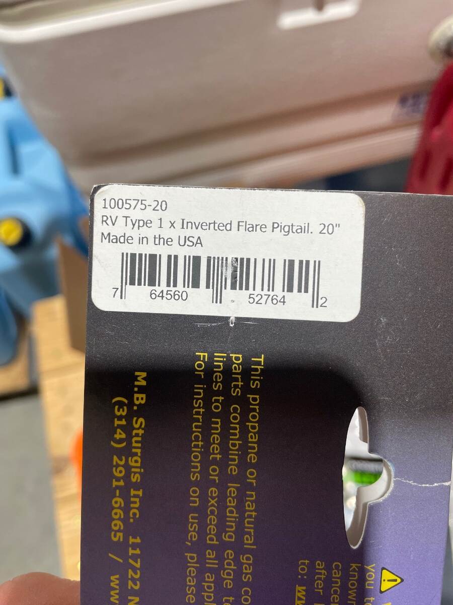
I replaced the original Gas-Flo regulator by Fairview Fittings and Mfg. Ltd. with a Marshall Excelsior 2-stage automatic changeover regulator model MEGR-253 in September of 2020 and have not had any problems with it. I replaced the original because it didn’t do what it was supposed to do one time and I didn’t want to give it a second chance. Marshall Excelsior MEGR 253 regulator with weather guard removed I used the mounting bracket off of the original regulator but you’ll have to order the weather guard (MEGR 862) as an extra item. It probably isn’t necessary because our regulators are covered but I put it on my regulator anyway. In May of 2026 I replaced the original pigtails with new MB Sturgis inverted flare 20” pigtails (Mfg # 100575-20) ... …and added 90 degree fittings on the inlet ports of the regulator. This removed the “S” in the pigtails. The hoses don’t actually stick out as much as the photo shows. They don’t reach the inside of the propane tank cover. I can’t find a “before” picture but this is the “after” picture. I ordered the brass 90 degree fittings (1/4 inch female 45 degree inverted flare x 1/4 inch male pipe thread) from McMaster Carr (item 6432T127). I ordered a couple extra to carry as spares. You’ll need to use pipe dope (sealant) on the pipe threads. Don’t use pipe dope or tape on flare fittings. Also, use the correct size open end wrenches on brass fittings. Adjustable wrenches (Cresent style), adjustable pliers (Channel Lock style), and pipe wrenches may slip and leave the wrench flats rounded or marred. Turn the tanks on and use soapy water in a spray bottle to check for leaks. Be sure to flip the changeover lever to both sides when checking for leaks. Also check the 3/8 inch female pipe thread outlet on the bottom of the regulator where the supply line goes to the trailer. Bill
-
RM 2454 Problem Heading into SE Colorado Boondocking
Townesw replied to Geronimo John's topic in Mechanical & Technical Tips
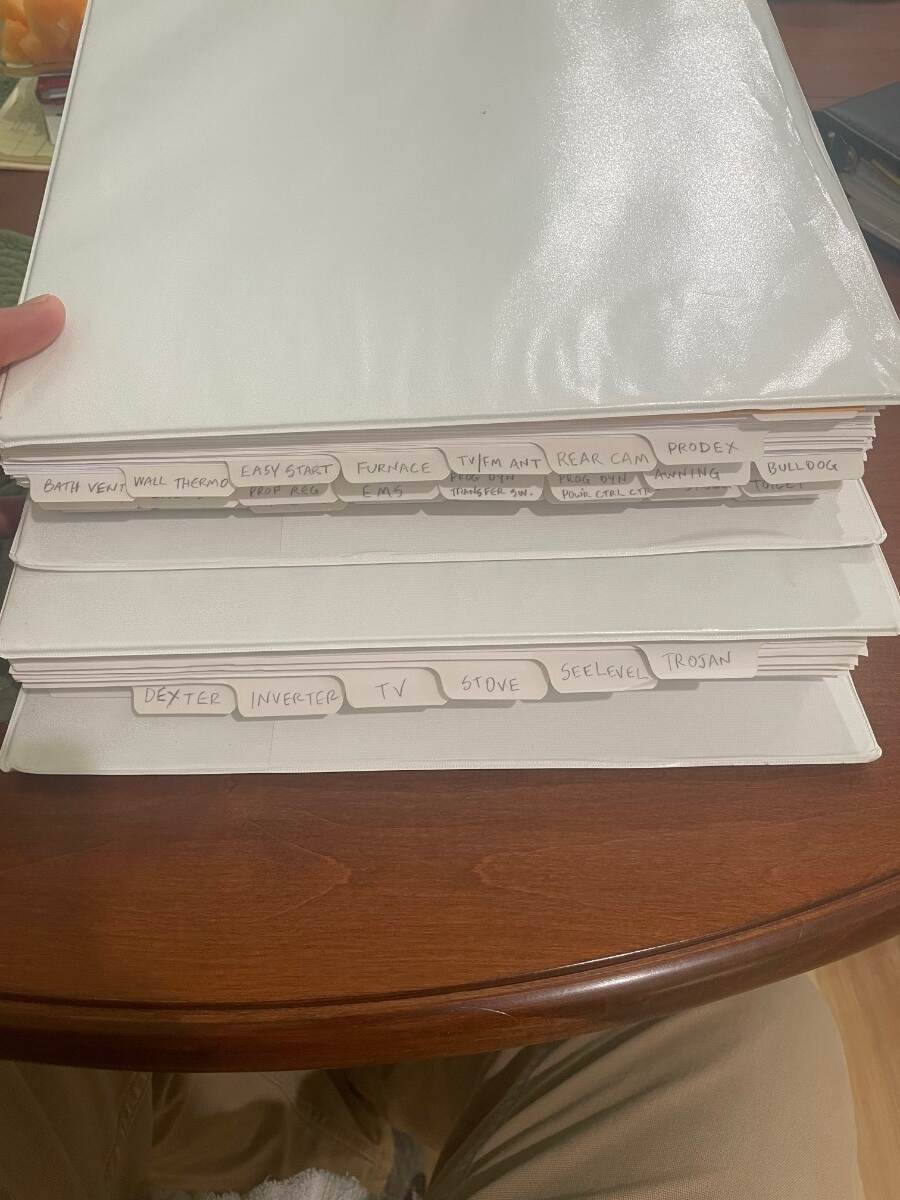
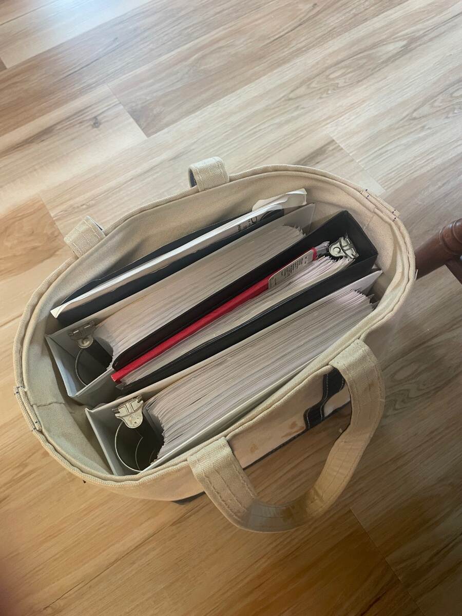
@Geronimo JohnI hope that has the answers that you are looking for. When I brought hull 313 home in March 2018 I crawled all over it taking pictures of data plates on equipment with model numbers and serial numbers. I then went online and found manuals (owner’s, installation, service, parts, whatever I could find) for the model and serial numbers that were on our Oliver. Some of the manuals on the Oliver site aren’t the correct manual for the model and serial number range of the equipment used in our Oliver. I then printed out the manuals and put them in 3-ring binders that I carry in a tote that fits under the front dinette seat. I know it’s bulky and isn’t as convenient as a link on a phone but I can open a manual and look at it and make notes while I’m working on something. Bill
-
RM 2454 Problem Heading into SE Colorado Boondocking
Townesw replied to Geronimo John's topic in Mechanical & Technical Tips
@Geronimo Johnsee if you can find any answers in this service manual https://fourwheelcampers.com/NewDometicRefrigeratorManual.pdf I had trouble getting my RM2454 to cool in Ashland VA last week after working fine for 3 weeks. It was just too hot there at 97F for the absorption cycle to work well. I temporarily added a double bladed window fan from Lowes. Still wouldn’t work even at night. Turns out that too much air movement is as bad as not enough. I turned the temporary fan off and the refrigerator started working again. Bill -
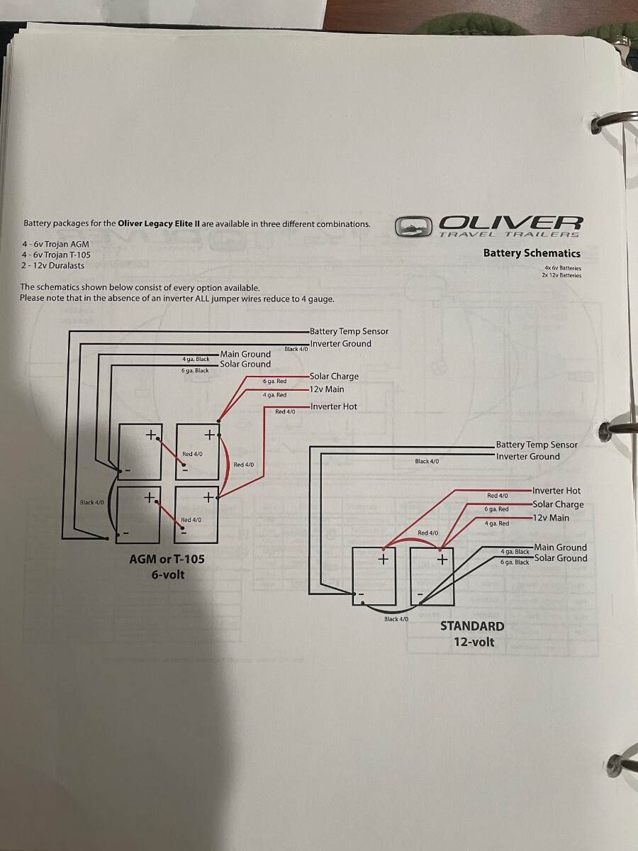
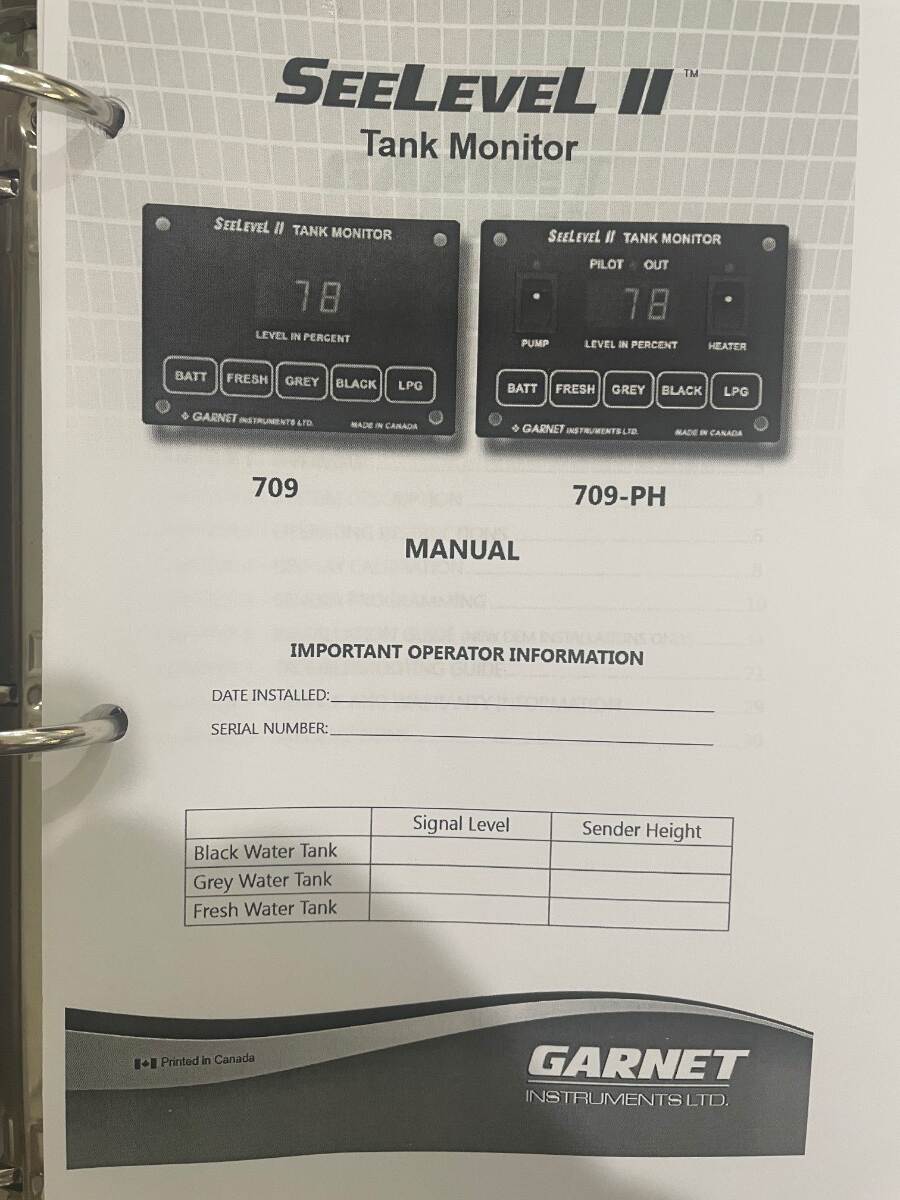
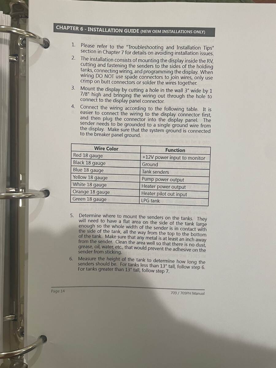
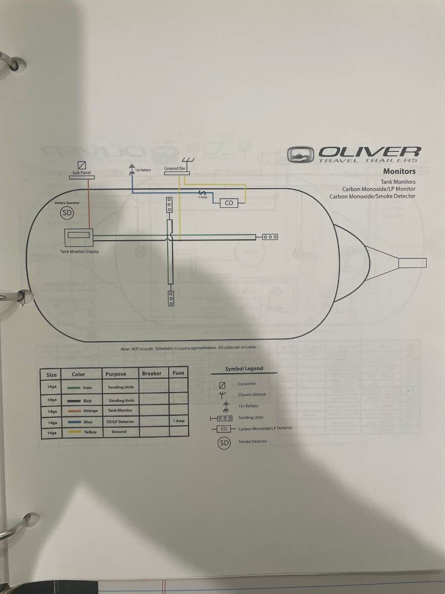
I have a manual for model 709 and 709-PH. The battery level displayed is determined by the voltage supplying the SeeLevel panel. As others have said see if it’s getting power. You said the tech plugged a new panel in and it was dead also. I can’t believe that the tech didn’t also check the fuses as that would have taken a few minutes. I would check the voltage going into the panel and work back from there This schematic is for 2018 LEII hull 313 so it might not be the same for your hull Bill
-
Spare Tire wobbles inside the fiberglass cover
Townesw replied to Dirt Duff's topic in Mechanical & Technical Tips
Mine wasn’t wobbly. It was very secure. Always has been tight. I just didn’t like the stain that the tire was leaving on the gelcoat. @Dirt Duffyou’ve got something else going on. You need to determine what is loose. -
Spare Tire wobbles inside the fiberglass cover
Townesw replied to Dirt Duff's topic in Mechanical & Technical Tips
Ok now I’m thinking that the second nut is a jam nut to hold the first nut on and both have backed off somehow. I would remove both nuts and see if the aluminum cylinder is threaded on that rod and check for something that might have loosened. Bill -
Spare Tire wobbles inside the fiberglass cover
Townesw replied to Dirt Duff's topic in Mechanical & Technical Tips
Yes I put those on there. I got a roll of stick-on UHMW from Rockler. People put it on tablesaw fences. Bill -
Spare Tire wobbles inside the fiberglass cover
Townesw replied to Dirt Duff's topic in Mechanical & Technical Tips
I have hull 313. This is what my spare tire mount looks like. It looks like you have an extra nut. Those two pieces of UHMW plastic keep the spare from rubbing and staining the gelcoat. I use a disk cut from a bucket lid to make the large ring that secures the spare easier to tighten. Bill
-
You can get an idea of the water quality at a campground by looking for places where their lawn or landscaping sprinklers have been spraying and at the faucet, pipe, post, and ground under the water hook ups. If these areas are stained there’s a good chance that the water might not be the quality that you are accustomed to. Bill