Townesw
-
Posts
542 -
Joined
-
Last visited
-
Days Won
22
Everything posted by Townesw
-

Spare Tire wobbles inside the fiberglass cover
Townesw replied to Dirt Duff's topic in Mechanical & Technical Tips
Mine wasn’t wobbly. It was very secure. Always has been tight. I just didn’t like the stain that the tire was leaving on the gelcoat. @Dirt Duffyou’ve got something else going on. You need to determine what is loose. -
Spare Tire wobbles inside the fiberglass cover
Townesw replied to Dirt Duff's topic in Mechanical & Technical Tips
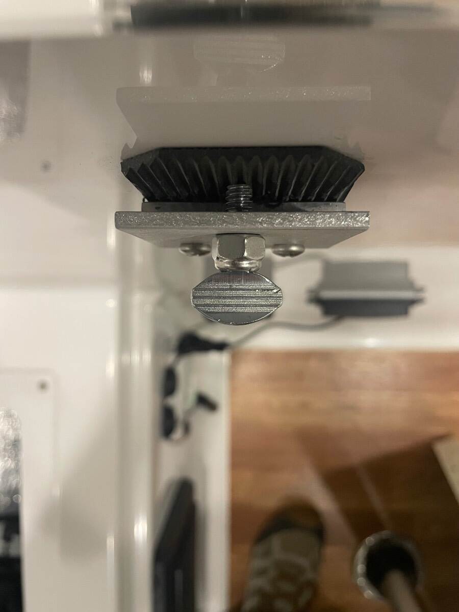
Ok now I’m thinking that the second nut is a jam nut to hold the first nut on and both have backed off somehow. I would remove both nuts and see if the aluminum cylinder is threaded on that rod and check for something that might have loosened. Bill -
Spare Tire wobbles inside the fiberglass cover
Townesw replied to Dirt Duff's topic in Mechanical & Technical Tips
Yes I put those on there. I got a roll of stick-on UHMW from Rockler. People put it on tablesaw fences. Bill -
Spare Tire wobbles inside the fiberglass cover
Townesw replied to Dirt Duff's topic in Mechanical & Technical Tips
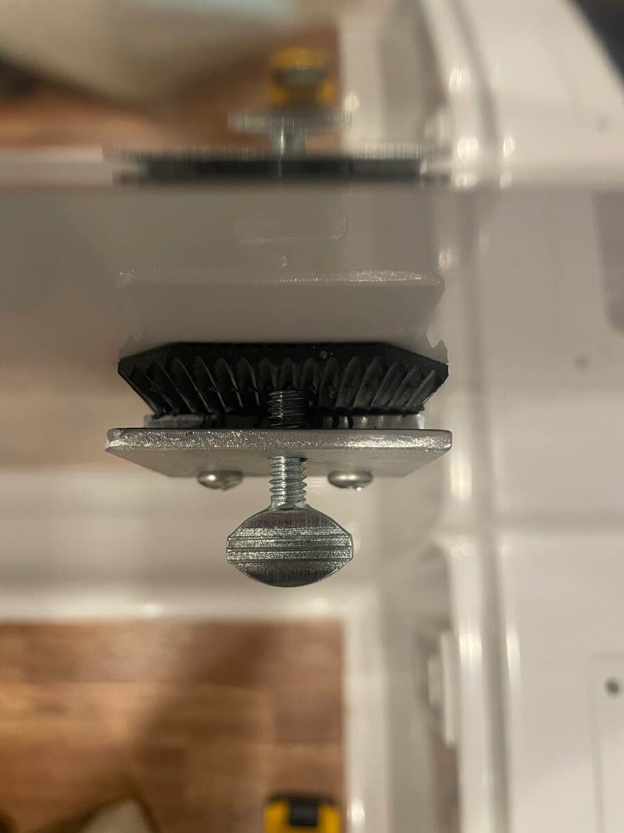
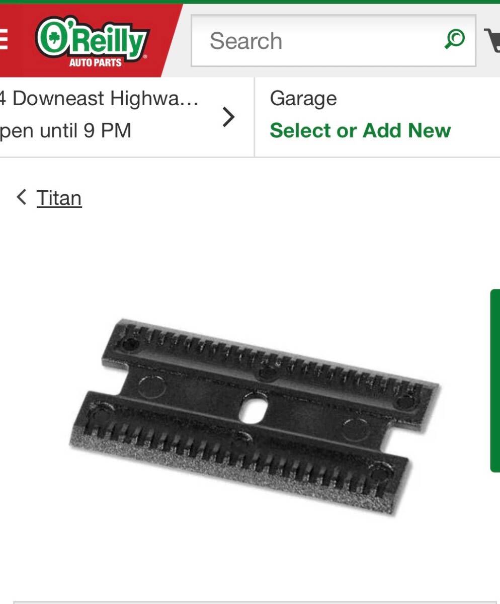
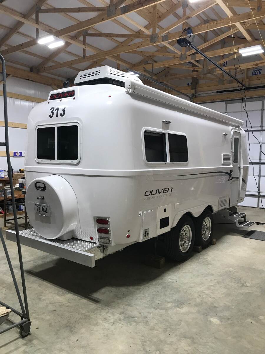
I have hull 313. This is what my spare tire mount looks like. It looks like you have an extra nut. Those two pieces of UHMW plastic keep the spare from rubbing and staining the gelcoat. I use a disk cut from a bucket lid to make the large ring that secures the spare easier to tighten. Bill
-
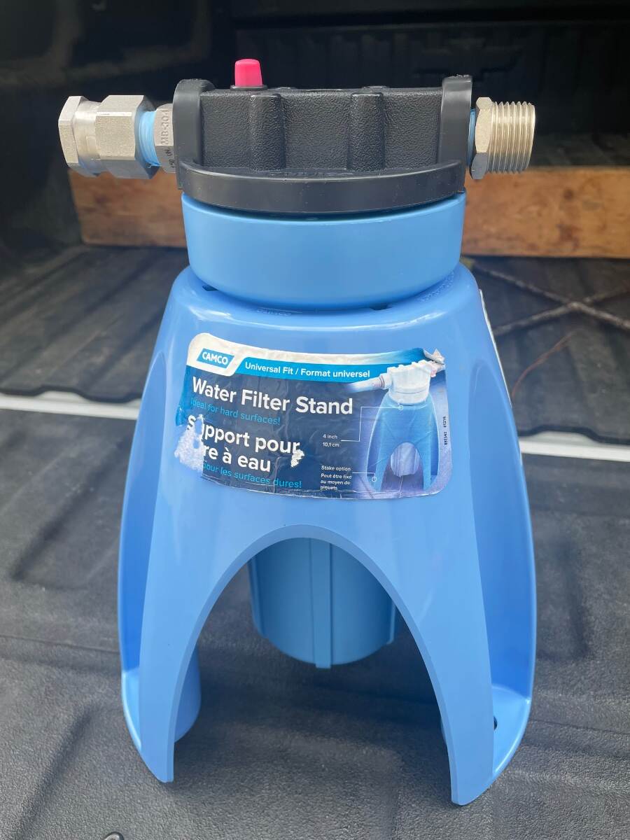
You can get an idea of the water quality at a campground by looking for places where their lawn or landscaping sprinklers have been spraying and at the faucet, pipe, post, and ground under the water hook ups. If these areas are stained there’s a good chance that the water might not be the quality that you are accustomed to. Bill
-
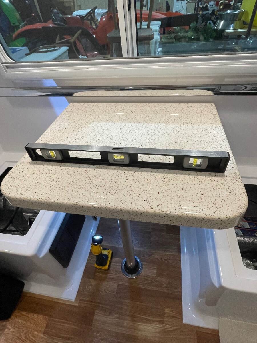
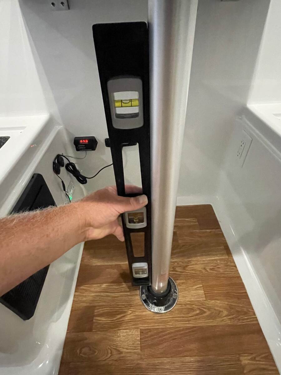
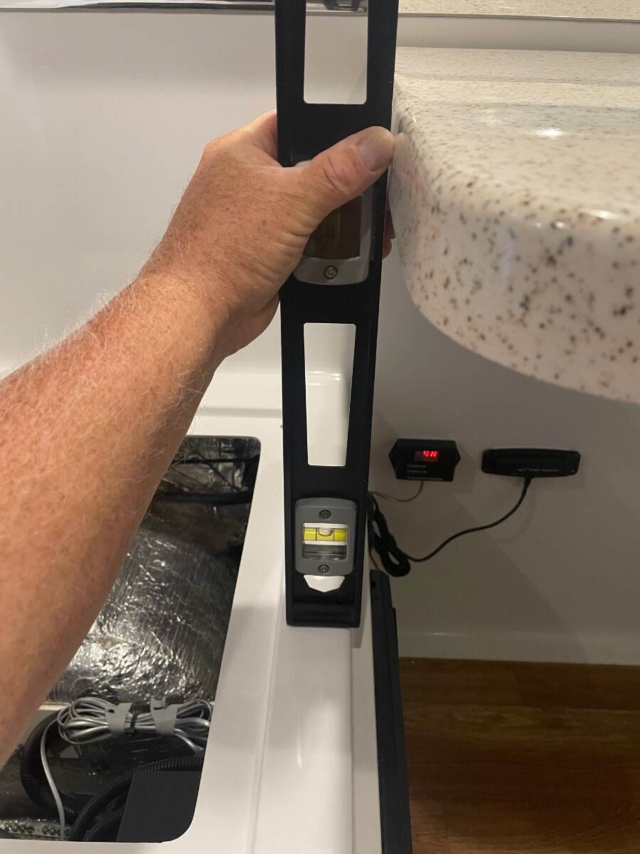
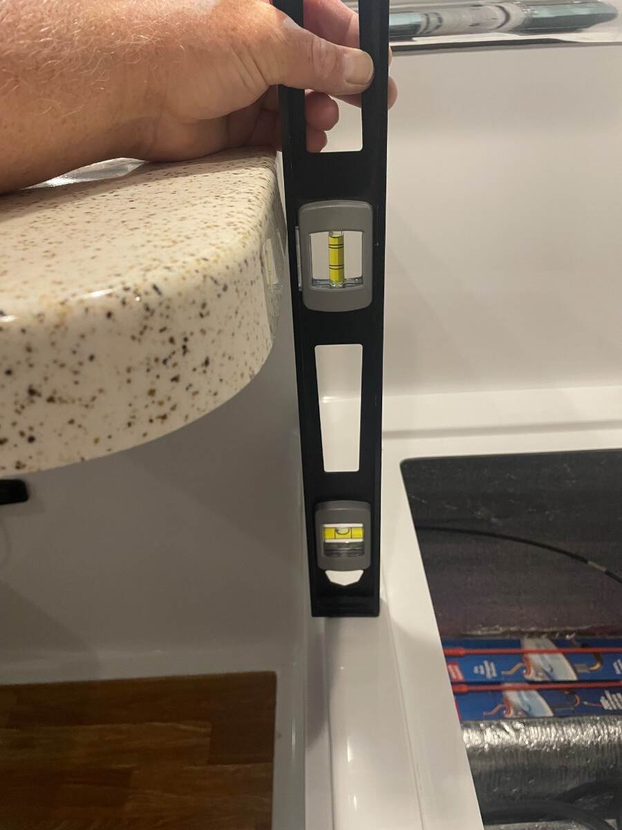
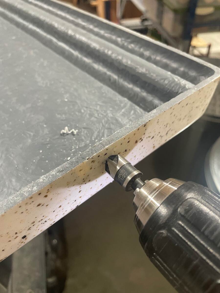
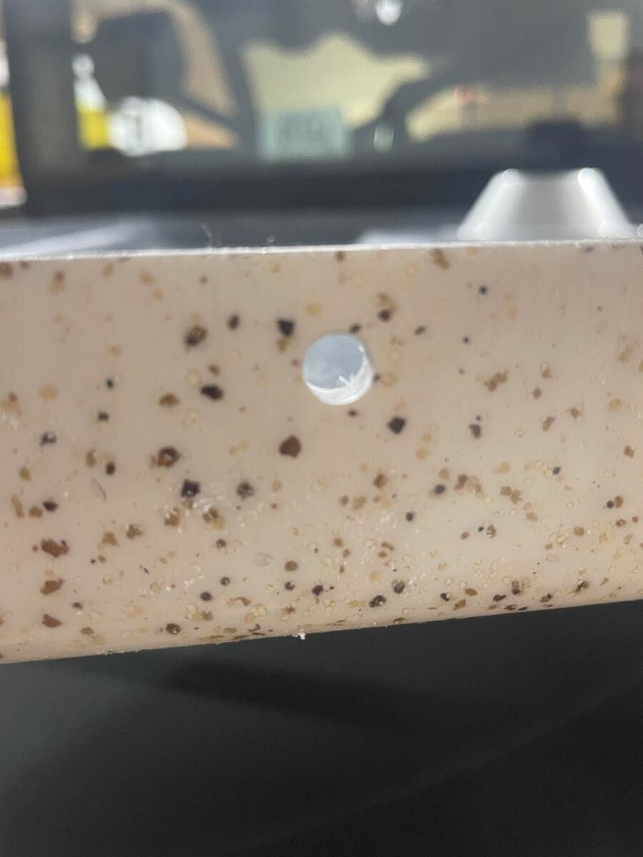
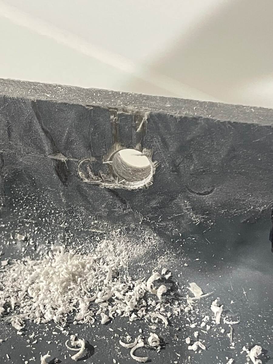
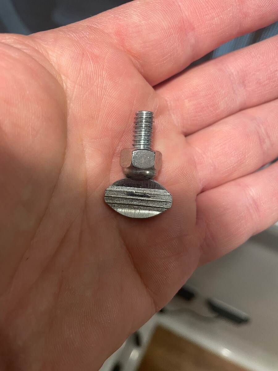
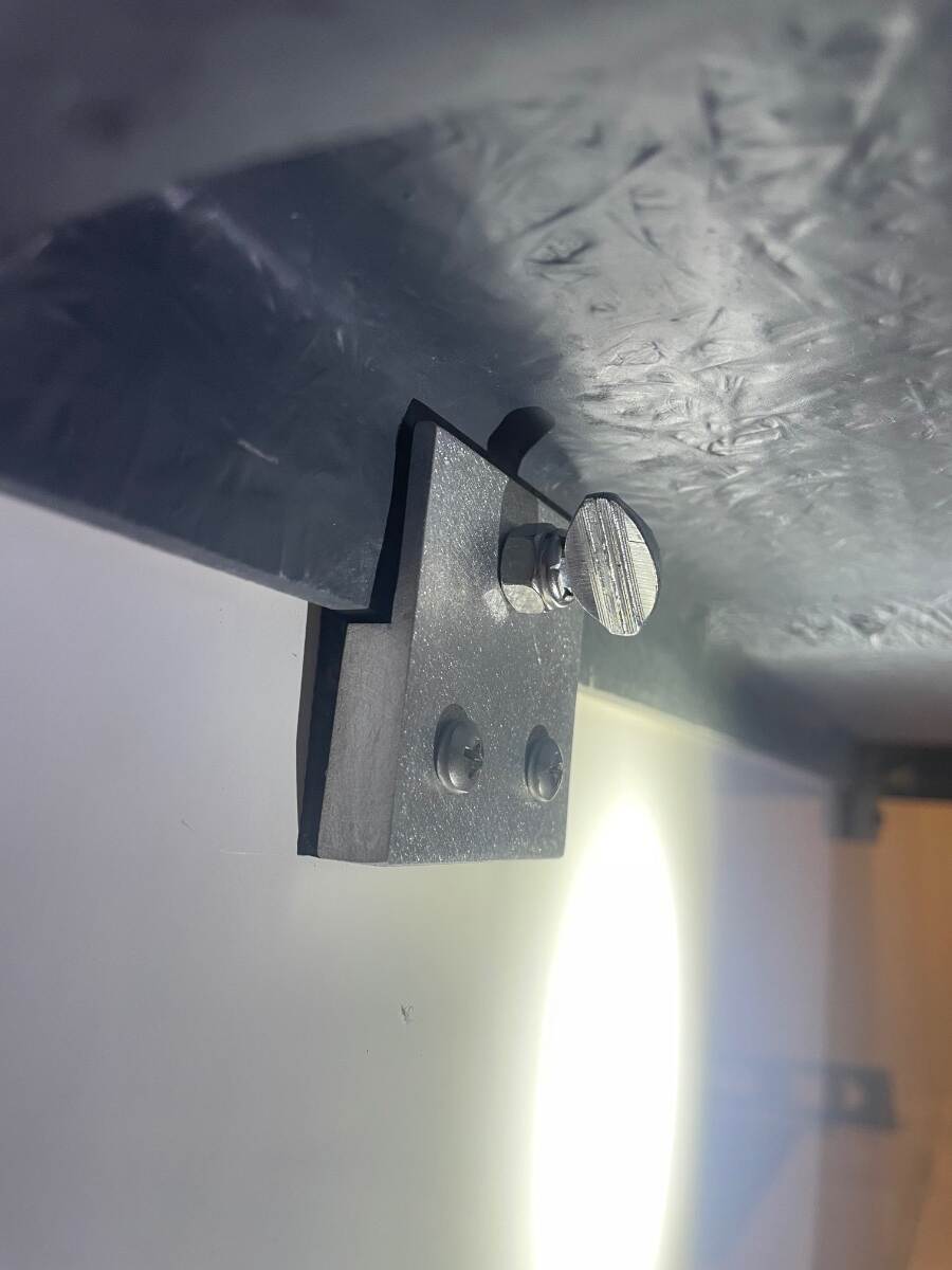
Occasionally I will place my hand on one of the front corners of our dinette table and it will cause the opposite back corner to lift up out of its bracket. I don’t tighten those two thumb screws down too tight because I don’t want to bend the aluminum bracket or break the screws that secure it to the wall. I drilled two holes in the back edge of the table so that the thumb screws would pass through them to prevent the table from slipping up out of the brackets. If you want to do this, start off by leveling your trailer then check to see if your table top is level. Make sure your table leg is plumb. Place a level against one side of the table, plumb it, and see how far the edge of the table falls away from the edge of the seat. Repeat the previous step on the opposite side of the table. I did this to make sure the table was centered between the two dinette seats before I drilled any holes. After verifying that the table is in the middle of the dinette mark the edges of each bracket and the location of the holes. Drill pilot holes using a small bit at very low speed. Enlarge the pilot holes with a step bit at slow speed. I stepped the hole size up to 1/4 inch. Use the step bit again to enlarge the holes on the back side of the table top so that you have a 1/4 inch hole all the way through the table edge. The step bit will chamfer the hole but I used a countersink bit to widen the chamfer. The thumb screws should be screwed in until they just touch the rubber bumper behind the bracket. I found that a 1/4 Nylock nut threaded on the thumb screw backwards made a good stop nut. I used a stainless steel nut because that’s what I had. The Nylock nut was the right height to stop the thumb screw at the proper depth. Finished product. If you find that the second thumb screw doesn’t quite line up with the second hole you can elongate one or both holes with a rat tail (round) file. I did this on hull 313. I don’t know if Oliver continued to mount the table this way so this might not work on tables in newer Olivers. Bill
-
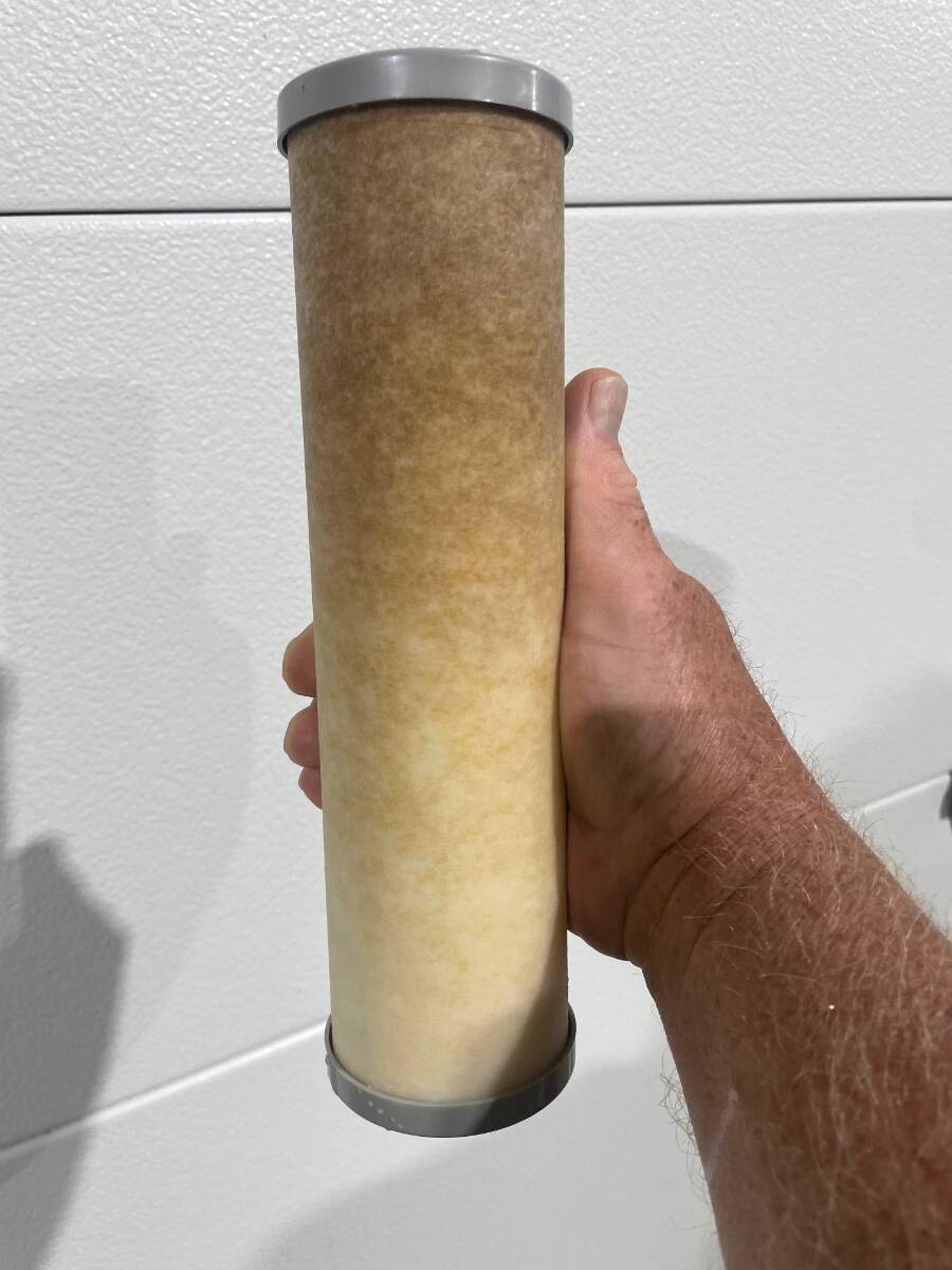
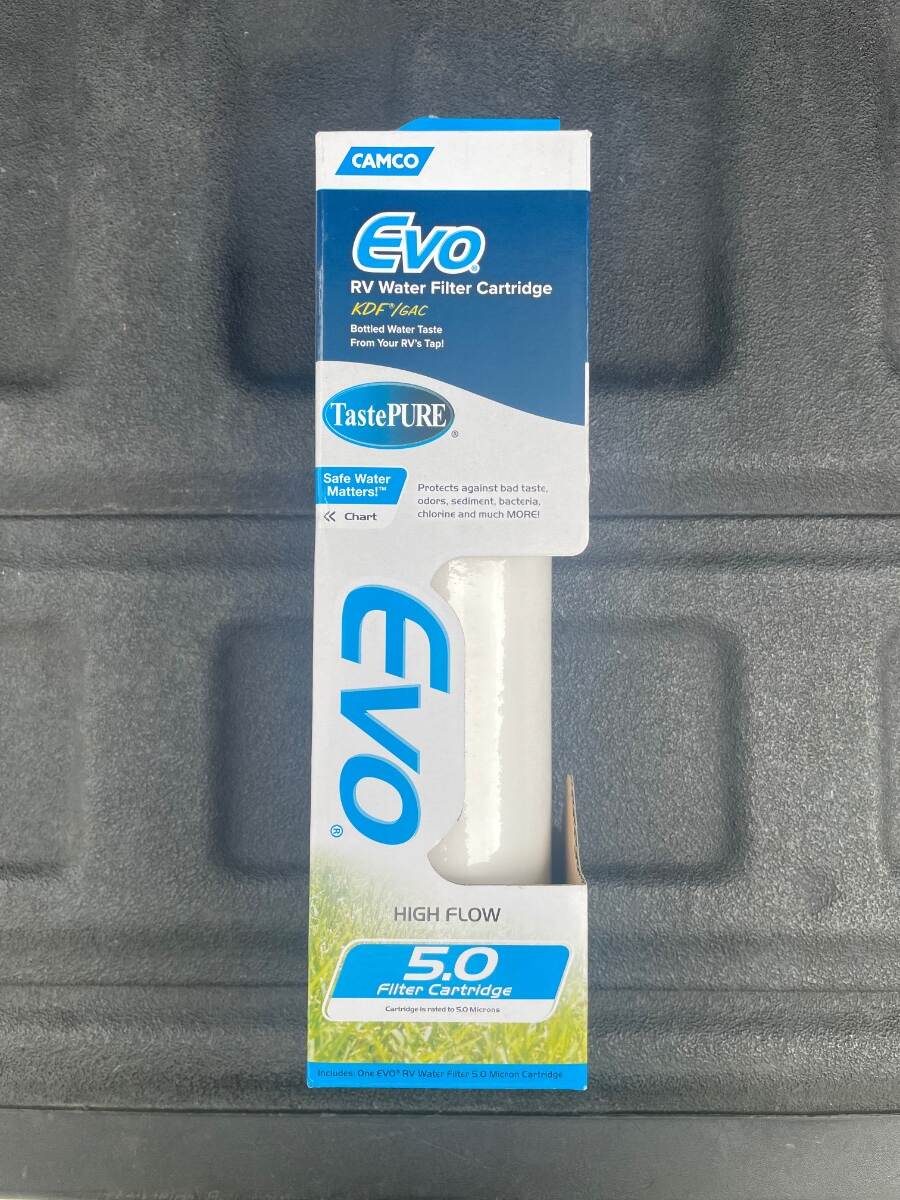
This is a Camco Evo water filter cartridge that has been used on one trip for 20 nights in 6 different campgrounds in 5 different states. We set up for 3 additional single nights in 3 more CGs where we didn’t hook up to the water. I don’t know which CG water caused it to look like this. We don’t drink campground water and sometimes we can’t even shower with it. This is not the worst we’ve seen. The worst case was near Leech Lake MN a few years ago where I had to change the cartridge after 1 night. Those of you using the blue bullet water filters should probably be changing them every few days. Water with high mineral or organic tannins content will stain your plumbing fixtures and certainly your clothes if you wash in it. Bill
-
Was the clamp open when you looked at it immediately following the incident? Bill
-
@mossemi And thank you Sir for your help. Bill
-
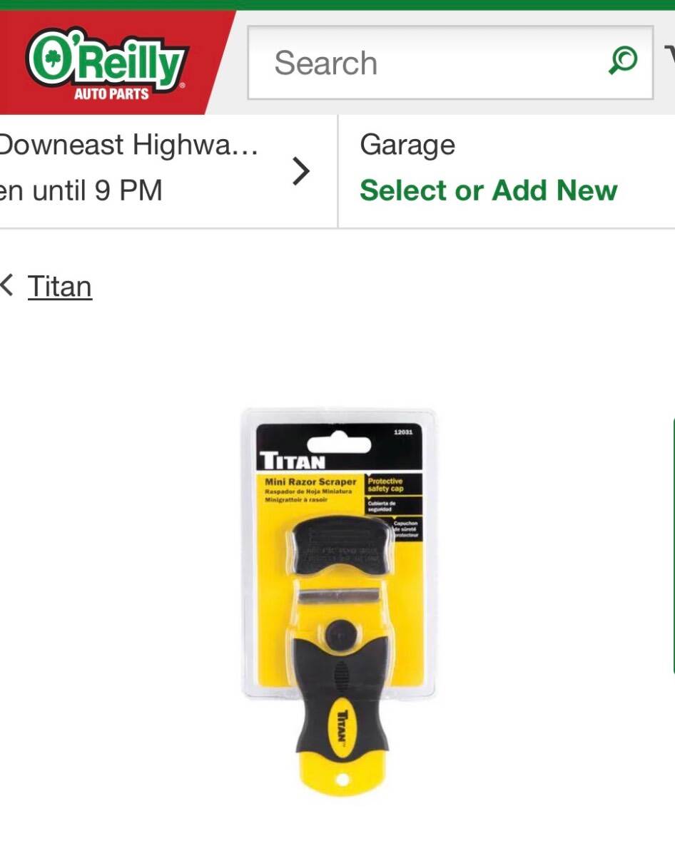
Caulk used Adhesive remover used Plastic razor blades from O’Reilly Razor blade holder also from O’Reilly Bill
-
Maxxfan Dome installation (previously orientation)
Townesw replied to Townesw's topic in Ollie Modifications
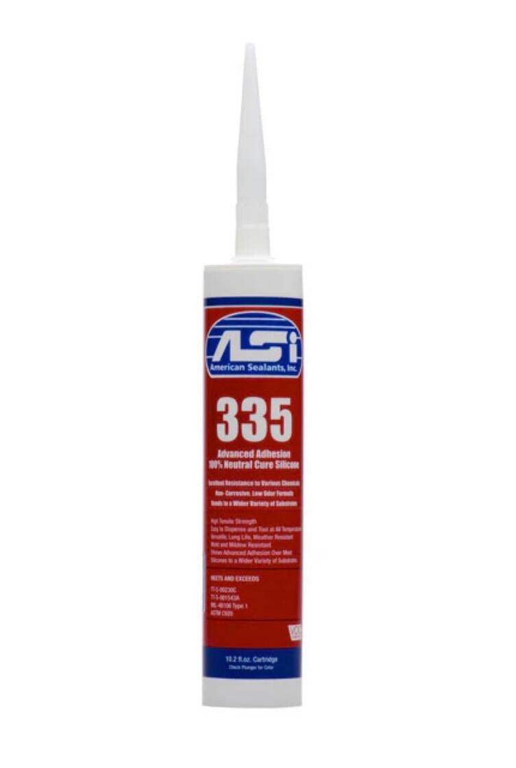
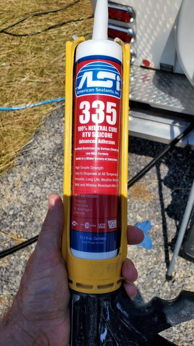
I sent a message to Meridian Products regarding the difference between ASI 335 and ASI 335WS. This was the response that I received: (And I apologize for the change in the font size) “…The 335 and the 335 Window Seal are the same base technology, the difference is the window seal label. In addition the Window is listed with AMMA for Window Installation.” I suspect that the “AMMA” that they refer to is actually “AAMA” , the American Architectural Manufacturers Association. Bill -
@jd1923 It is interesting that our tongue weights are the same but your total trailer weight is 600 lbs more than mine. Bill
-
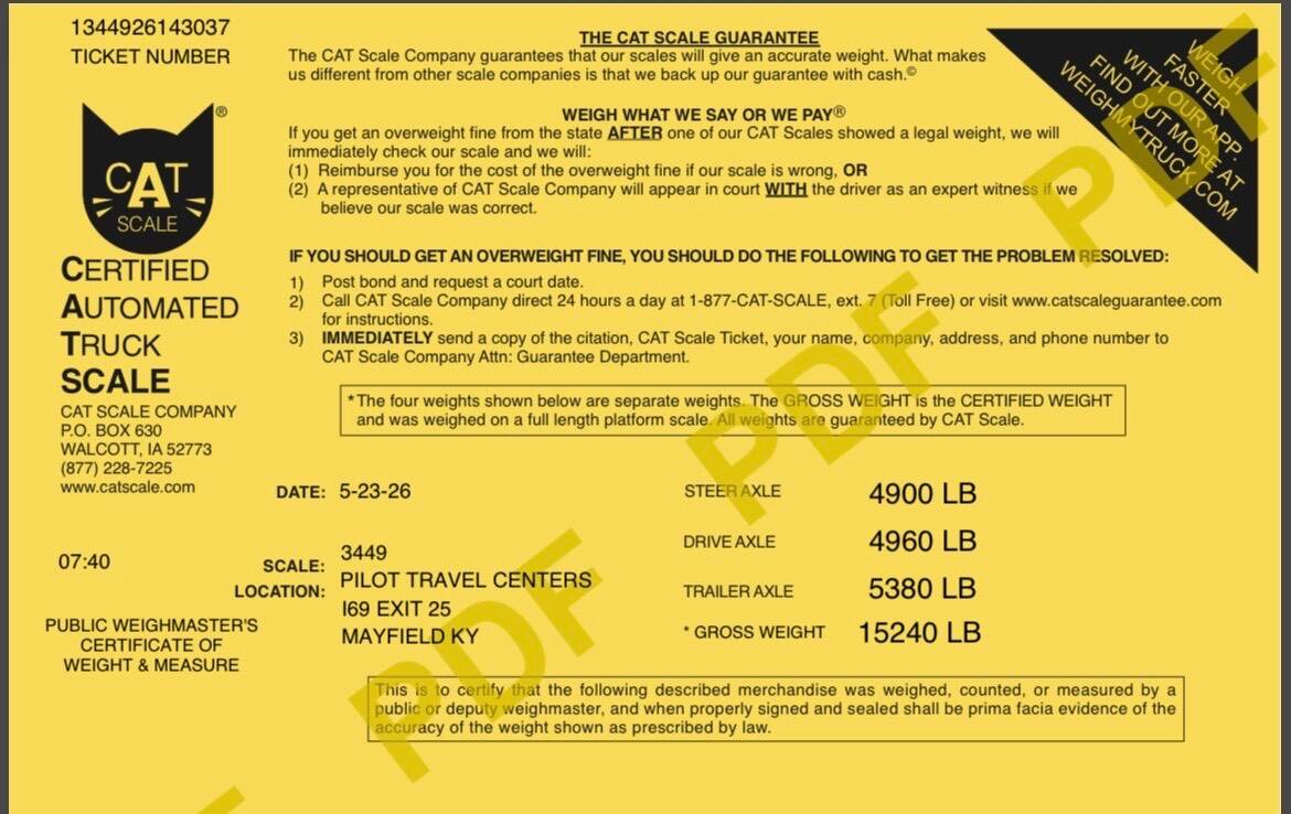
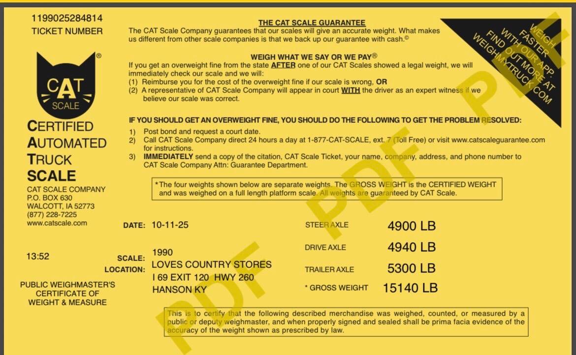
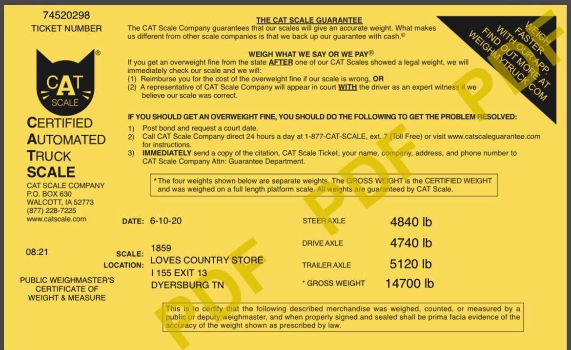
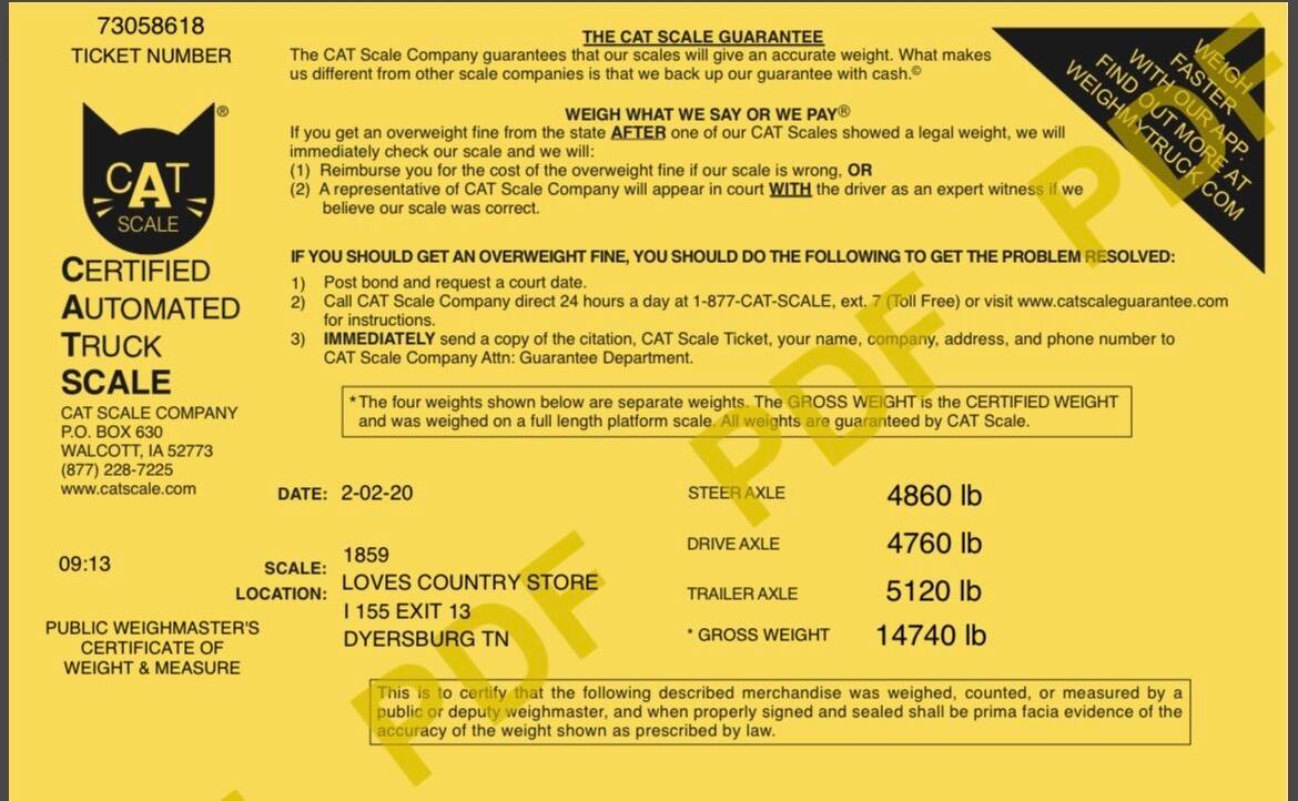
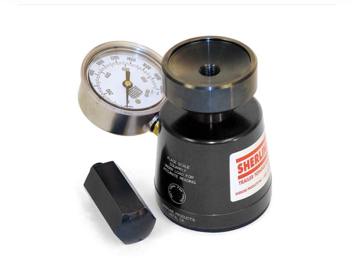
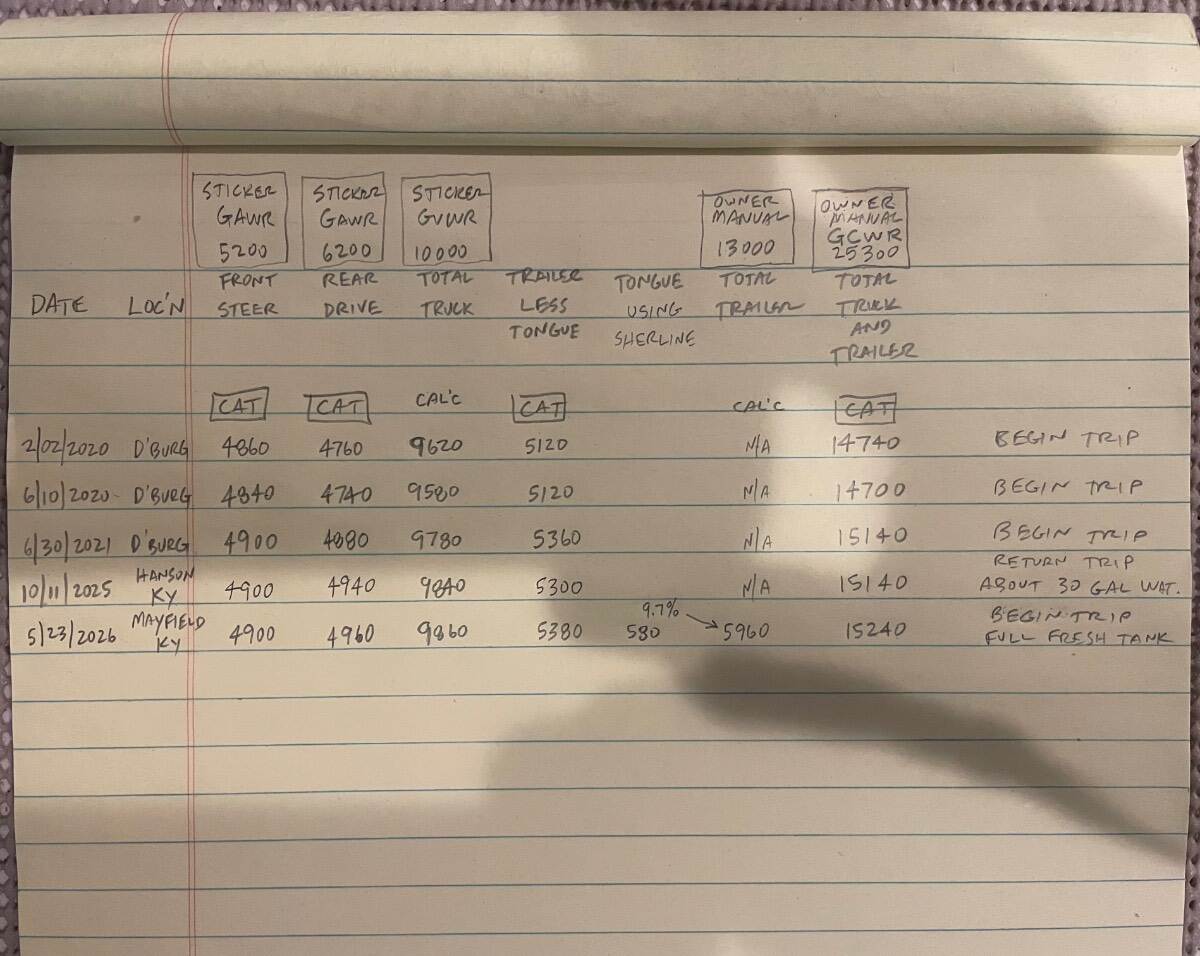
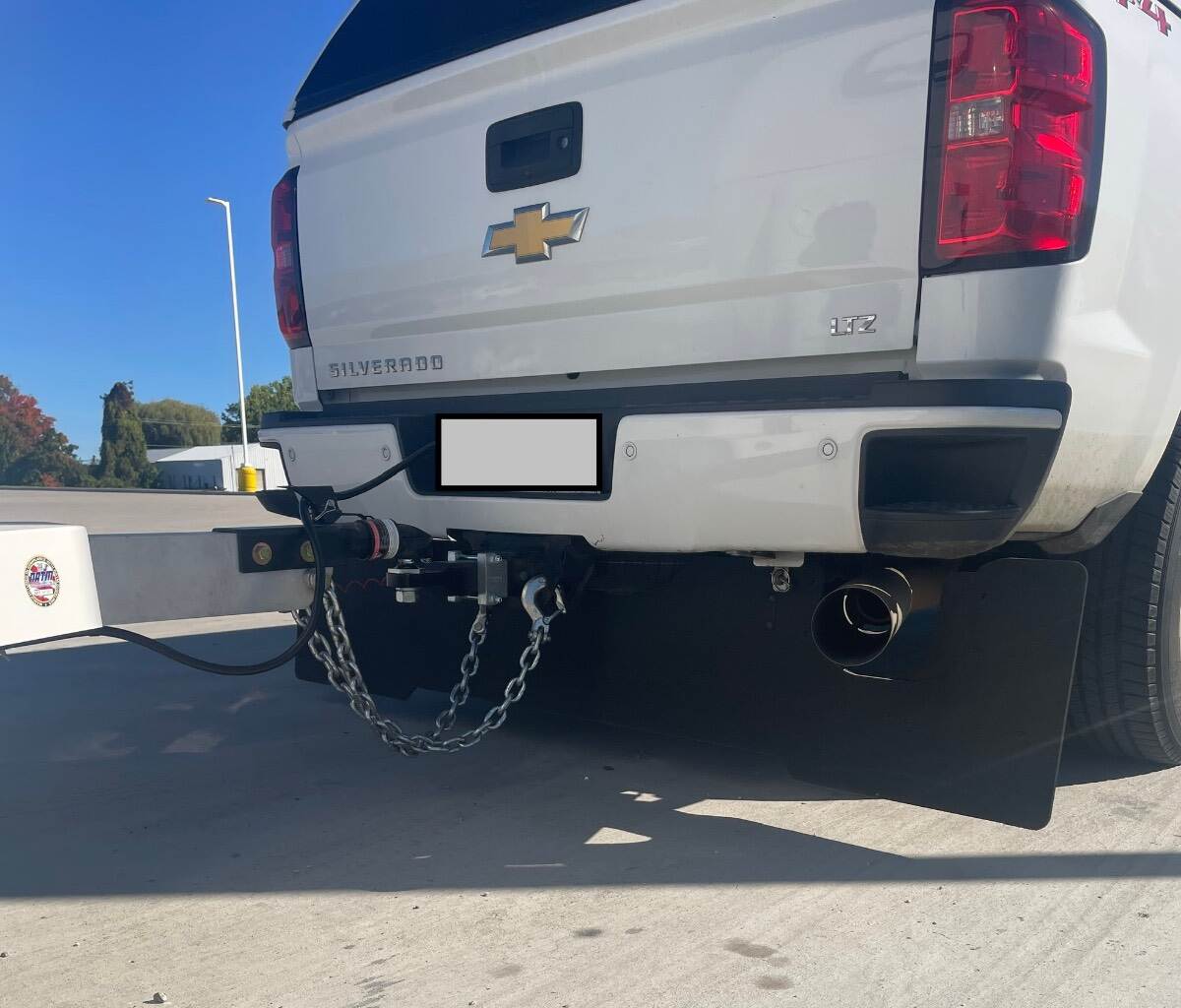
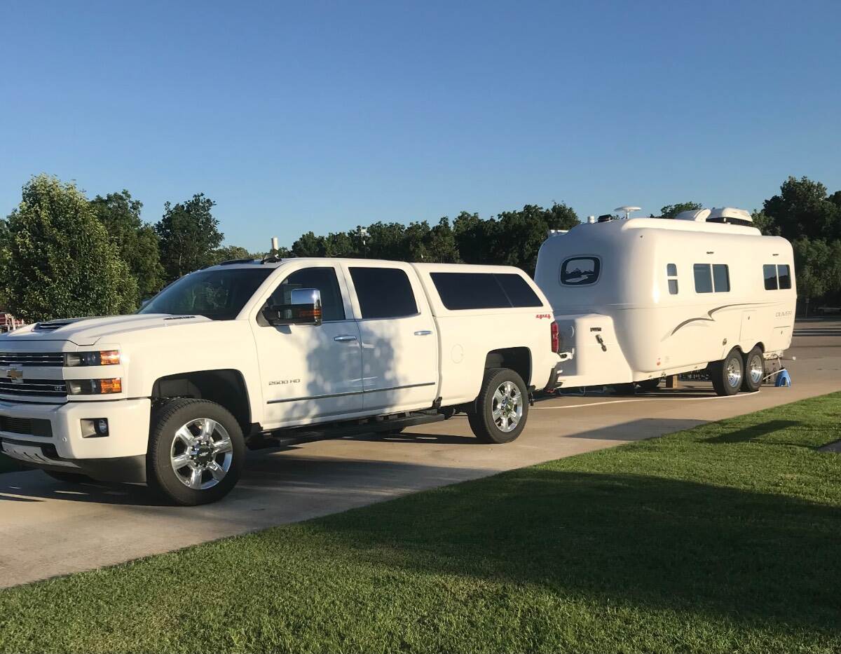
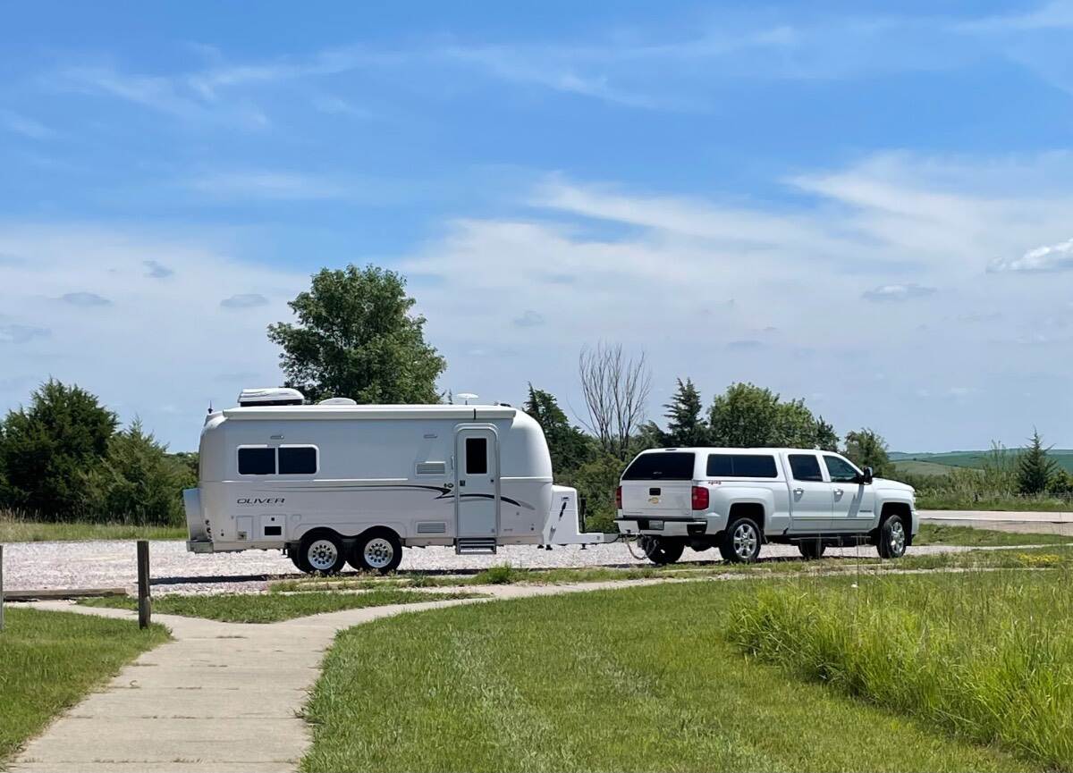
Here are my scale tickets since I have started using CAT scales. I tow with a 2019 Chevrolet Silverado LTX 2500HD with 6.6L Duramax and 6 Speed Allison automatic transmission. ARE bed topper with full bed. Both front seats occupied. Full width RockStar Commercial Tow Flap. Full diesel tank 36 gallons. Sticker FRT GAWR 5200 Sticker RR GAWR 6200 Sticker GVWR 10,000 Owners Manual Max trailer 13,000 Owners Manual GCWR 25,300 Just started using a Sherline Tongue Weight Scale Loaded tongue weight at the beginning of the current trip is 580 lbs. Full fresh water tank (30 gallons of water weigh 250 lbs). Empty black and gray tanks. Full 30 lb propane tanks (About 110 lbs). Full refrigerator. No tongue basket. No bumper attachments. Four AGM batteries. No solar. Here’s a spreadsheet that I scratched out this morning “CAT” is a weight off the CAT scale ticket. “CAL’C” is a calculated weight “Sticker” is a weight off of the vehicle placard. “Owners Manual” is a weight out of the owners manual for my truck. I tow without a weight distribution hitch. Trailer brake gain usually set on 4, bump up to 5 or 6 if raining and/or hilly. Front 60, rear 75, trailer 50 cold tire pressures. Tow/haul, exhaust braking, Cruise control on. Original brakes, I’ve installed new Timken or NTN bearings at 6,400 miles and 20,000 miles, and will install new bearings at about 32k. Just over 30,000 miles total on the trailer. Trailer stays in heated and air conditioned shop when at home. I am very pleased with how the truck and trailer operate together at these weights. I’ve posted this information for those who are interested in how other folks tow. Bill
-
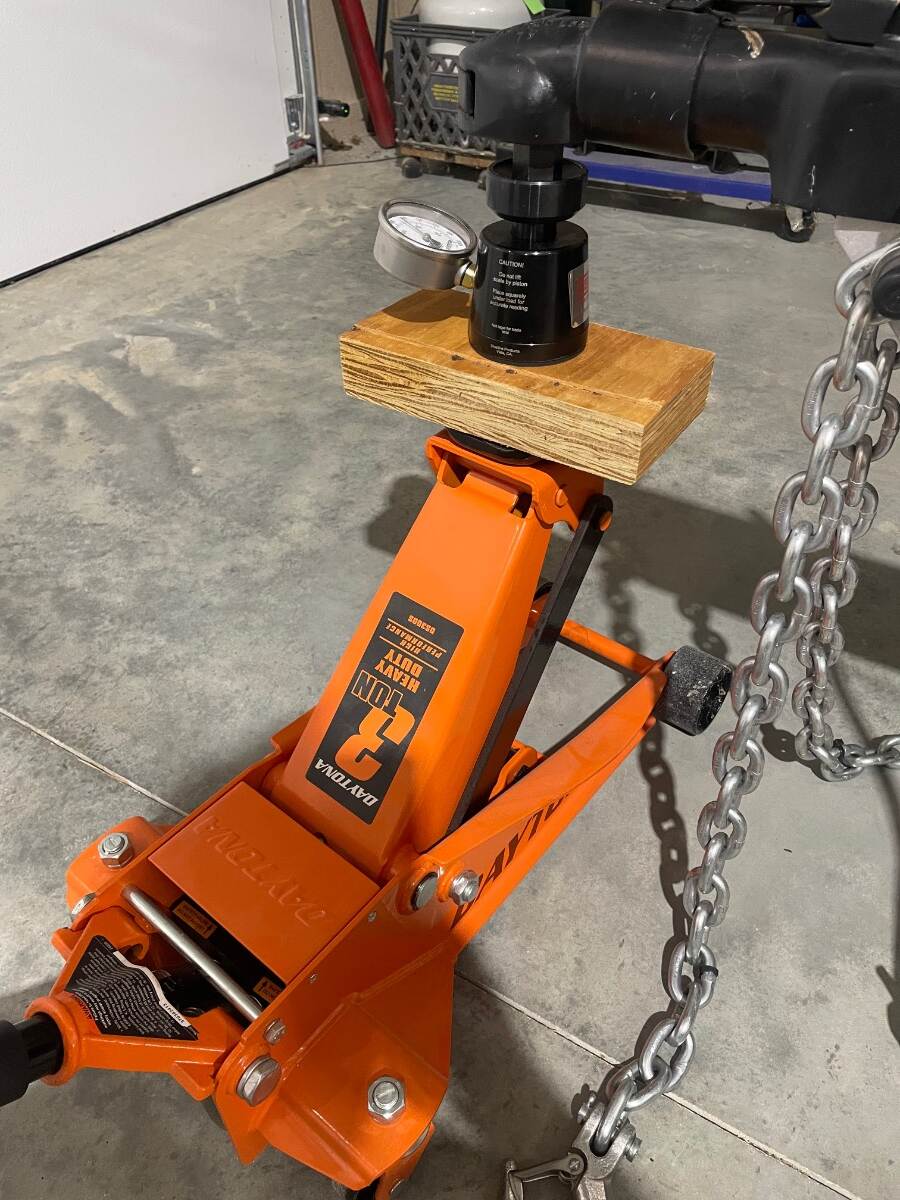
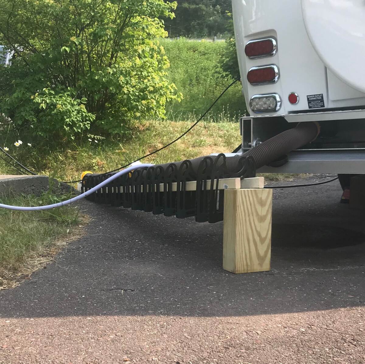
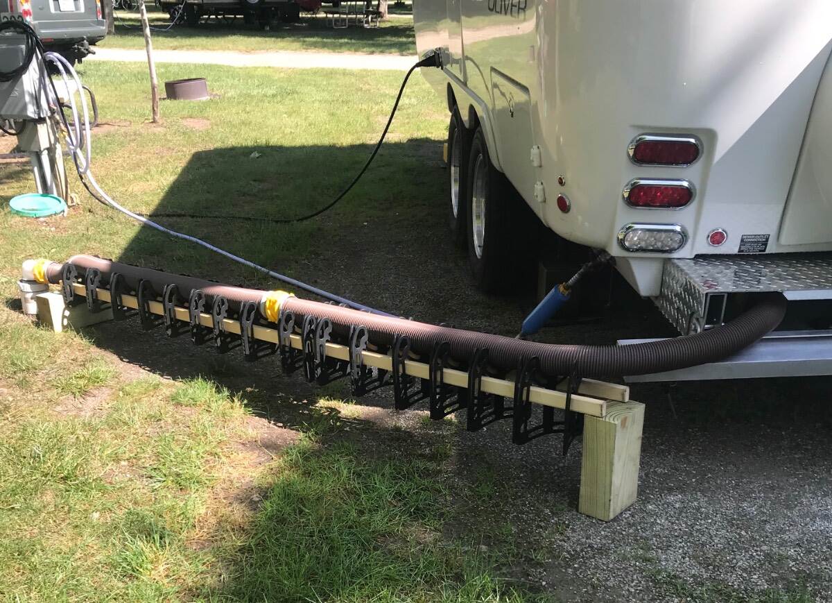
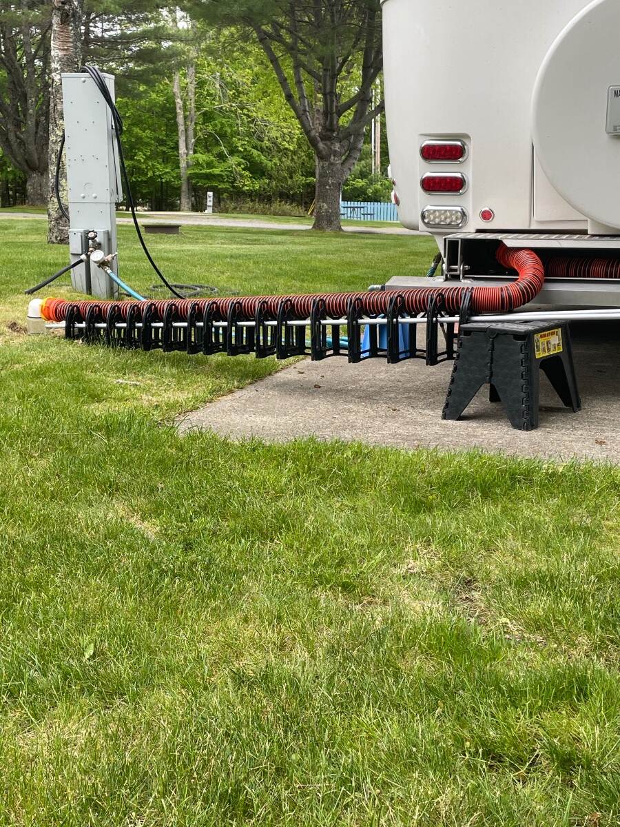
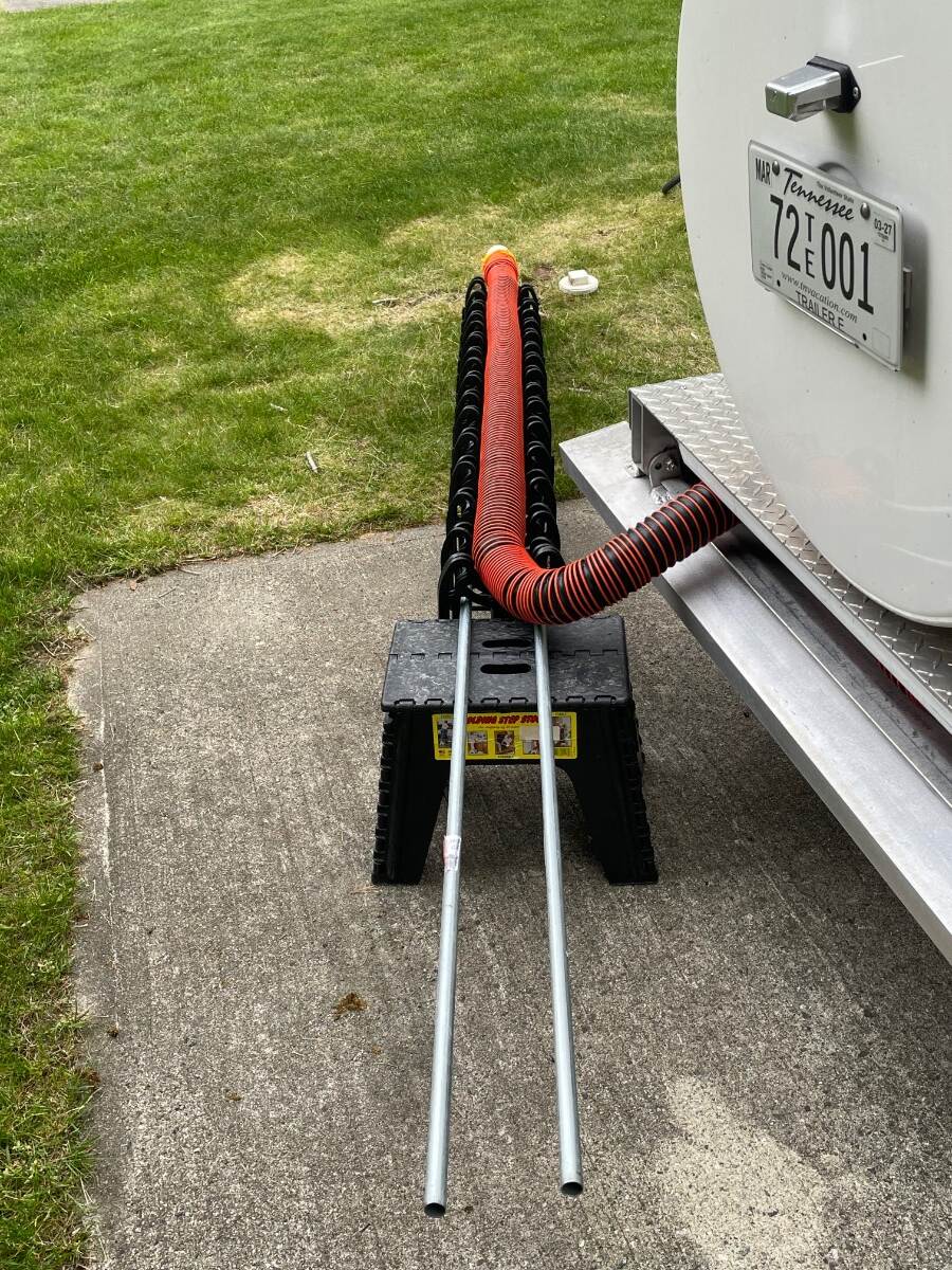
Here’s a trick to dump your tanks when the sewer hookup is uphill from your bumper. Here I used (2) 1”x2”x8 ft from an Ace Hardware store on the Keweenaw Peninsula Houghton MI Door County WI This time I picked up (2) pieces of 1/2”x10 ft EMT conduit from HD in Ellsworth ME. I like the conduit better than the 1x2 wood. The sewer hose supports slide better on the conduit and when I get home I’ll cut each conduit in half and turn a steel rod to just fit inside the conduit to make a splice for the halves. I thought I could stick the whole 10ft length into the Oliver aluminum rectangle frame rail but bolts through the rail prevent my doing this. Bill
-
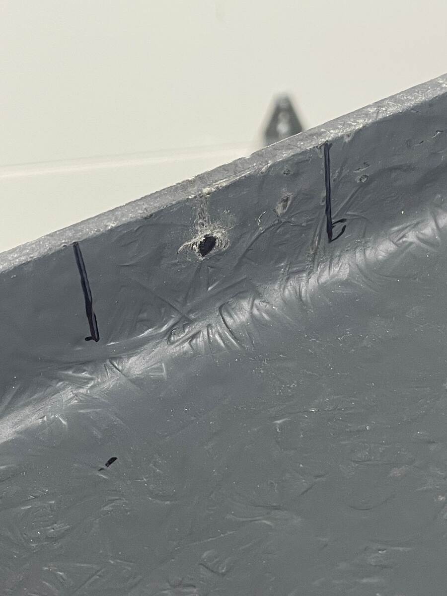
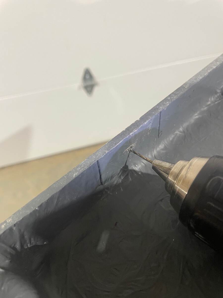
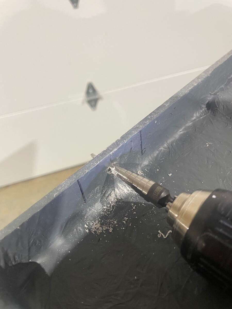
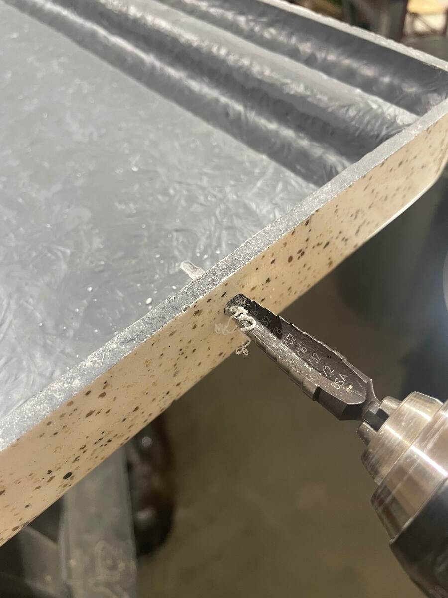
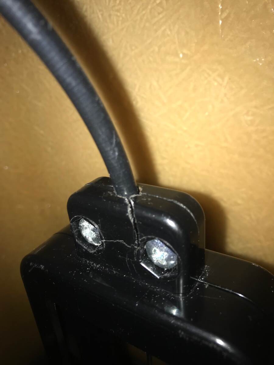
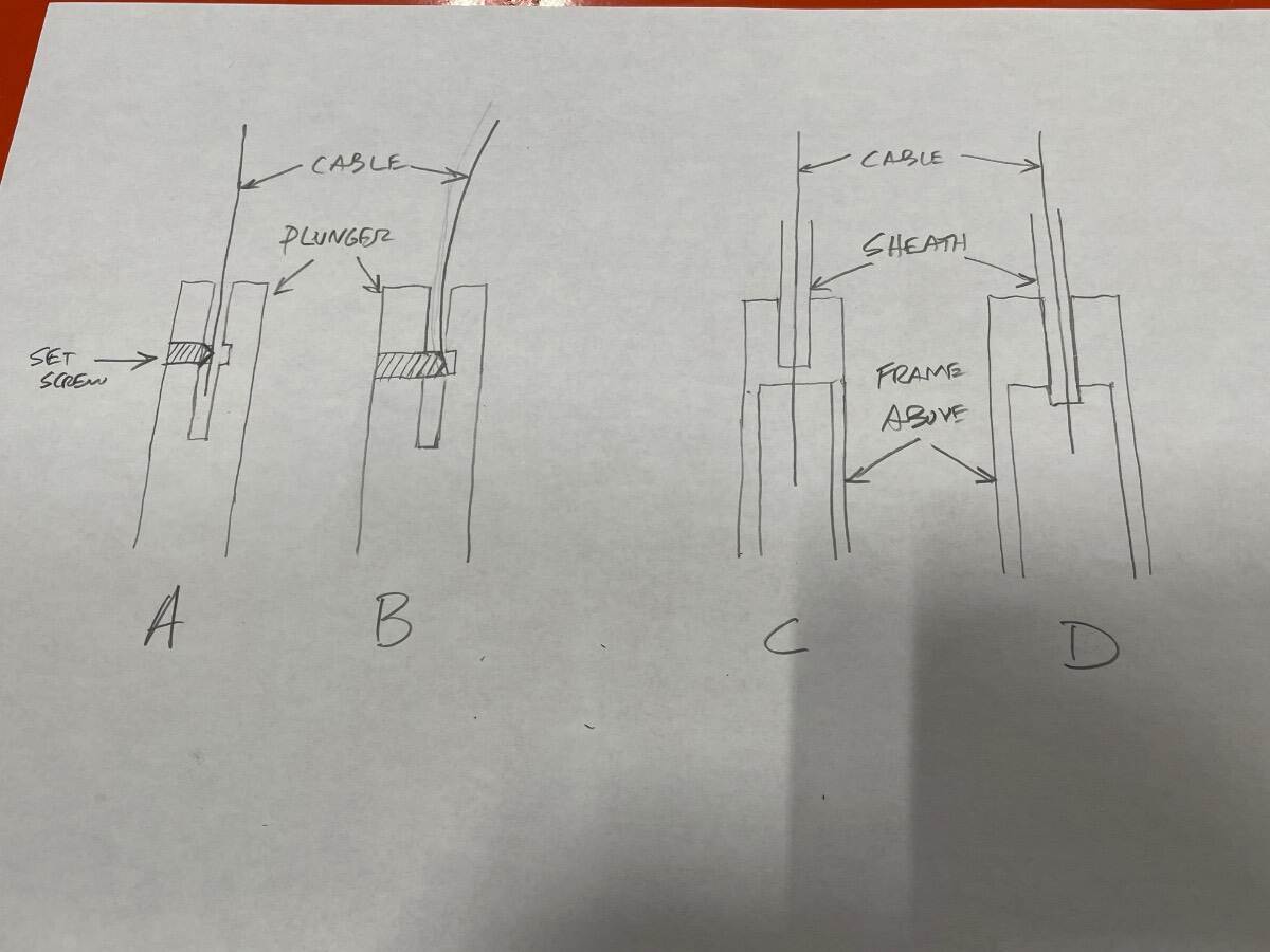
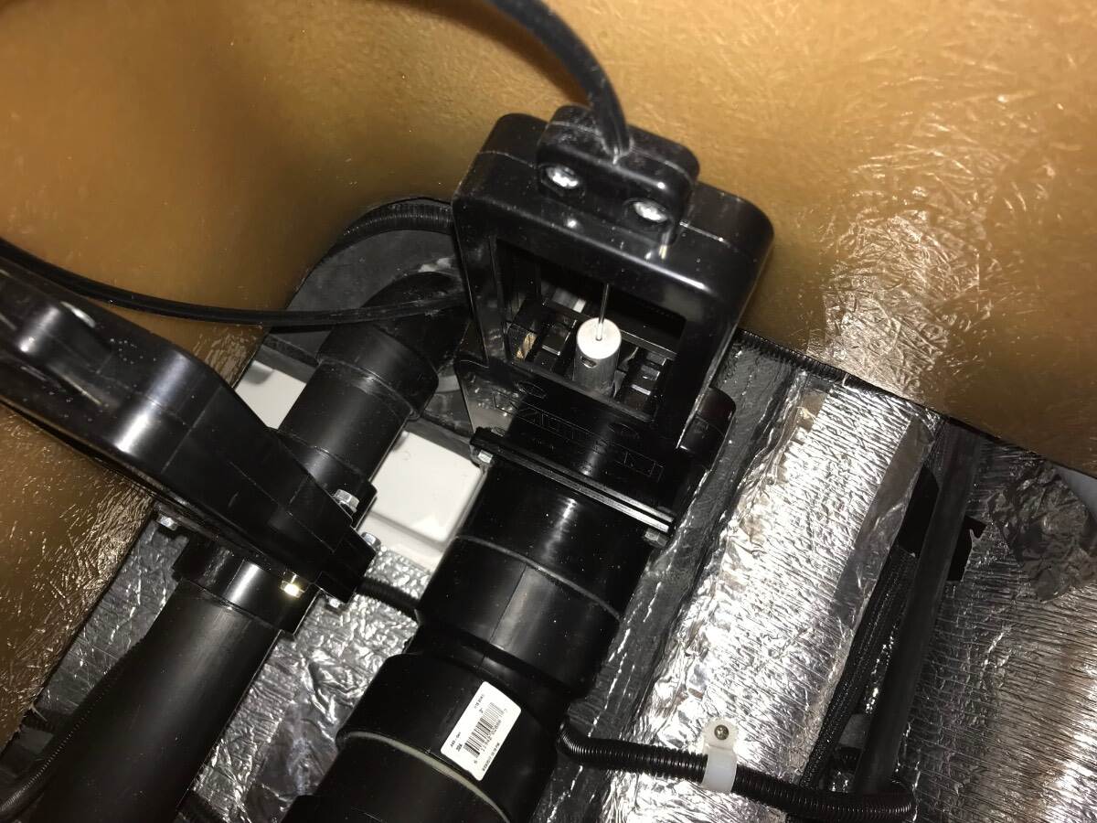
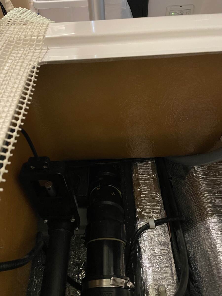
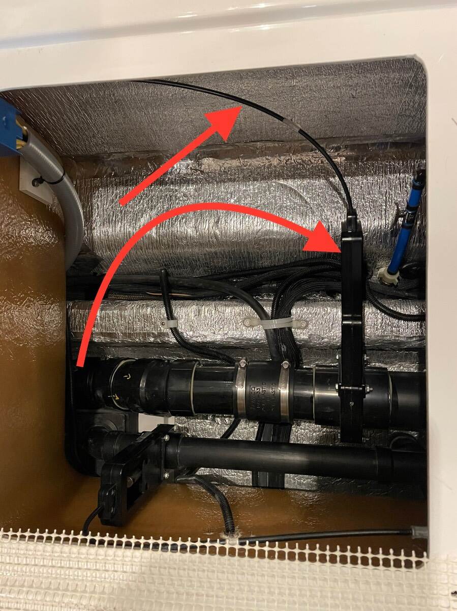
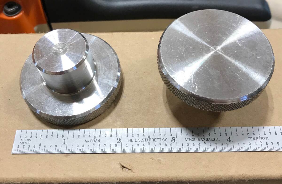
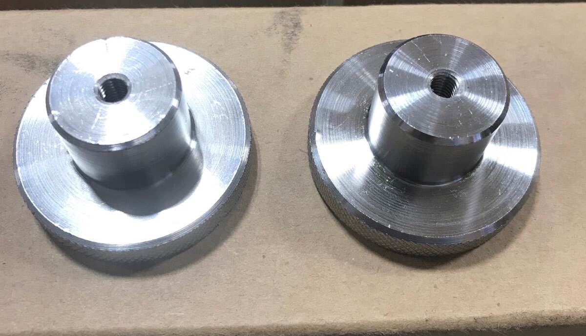
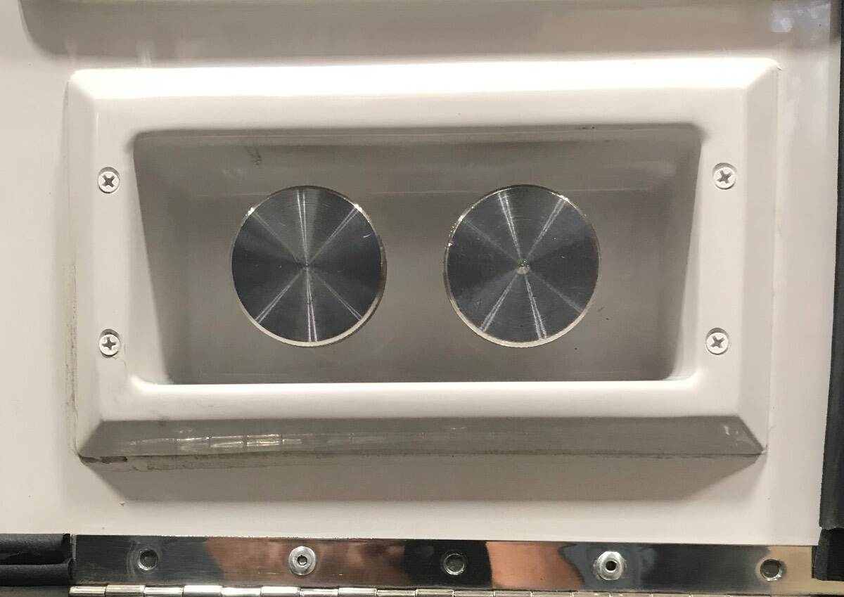
My black tank dump valve was hard to close from day 1, March 14, 2018. During the Summer of 2018 I found the installation instructions for the cable and valve and realized that it was at best a marginal install. I pulled the cable out and lubed it with a dry type lubricant and straightened the kink in the very end of the cable where the factory had screwed the set screw in and barely caught the end of the cable and bent it into the hole opposite the threaded set screw hole. This caused the cable to be slightly bowed which didn’t help the situation (See A and B below) and didn’t make valve closure any better. I also noticed that the clamp on the frame above the valve was broken and didn’t properly secure the cable sheath. I could get some clamping force but not enough to suit me. Given this and the fact that the cable/sheath/clamp length and position relationship weren’t going to permit full closure of the blade (if you have worked on bicycle brakes, throttle cables, choke cables you know what I mean) I decided to modify the clamp portion of the frame above the valve. I disassembled the frame and drilled the hole where the sheath is clamped through the bottom of the frame (See C and D below). I used a drill size that would create a tight fit of the sheath in the clamp hole. I reassembled everything, pushing the sheath lower in the frame (which also allowed me to push the end of the cable down past the set screw in the plunger) and this permitted the blade to completely close. Now with the valve closing completely I wasn’t having water in the sewer hose when I went to hook it up at a campsite but it was still difficult to open and close the valve due to the routing of the cable. Winter of 2020, I finally accepted that manual operation of the dump valve wasn’t going to be as smooth as I expected it to be so I ordered (2) stainless steel knobs from McMaster Carr, drilled and tapped them to fit on the opposite end of the cables, and installed them in place of the Valterra handles that came on the trailer. This made it easier to pull and push the cables without concern about breaking the handles. I think it was Spring 2021 when I talked to the service department about my findings and what I had done and that I still wasn’t pleased with the force required to operate the valve and that I thought it was due to the cable routing. They offered to relocate the black tank dump valve and since the sheath clamp part of the frame was broken I took them up on their offer. The service department relocated my black tank dump valve as shown below. This resulted in the valve assembly being tilted about 75 degrees from the vertical to the street side and the cable was rerouted from under the dinette seats to the street side of the dinette seat. This resulted in an improvement in valve operation, not perfect, but it is an improvement. Valve location before After, showing only the 1.5 inch sink/shower drain valve New location of the valve showing also the new routing of the cable I hope that this information is helpful to those trying to improve the operation of the black tank dump valve. I also hope my high school English teachers don’t read this. They would be appalled. Bill Very early 2018 Hull 313
-
Maxxfan Dome installation (previously orientation)
Townesw replied to Townesw's topic in Ollie Modifications
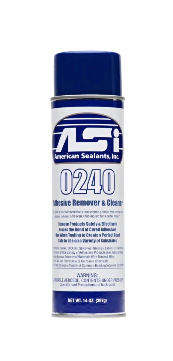
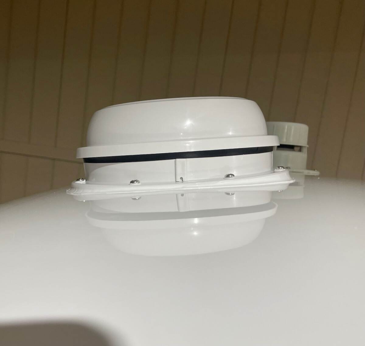
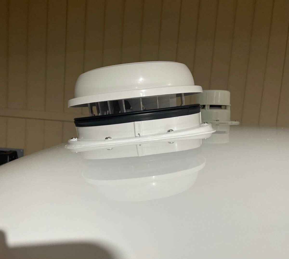
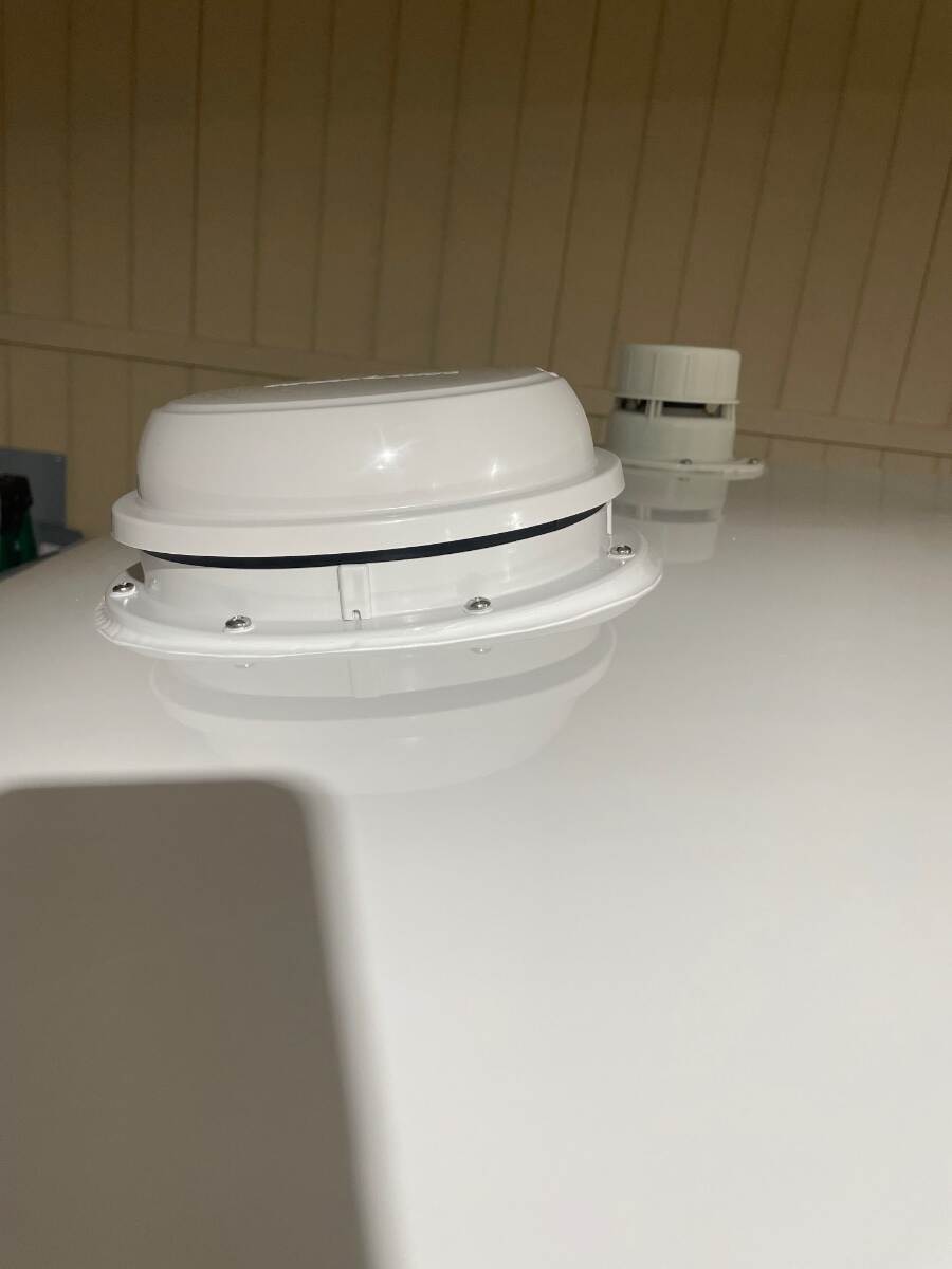
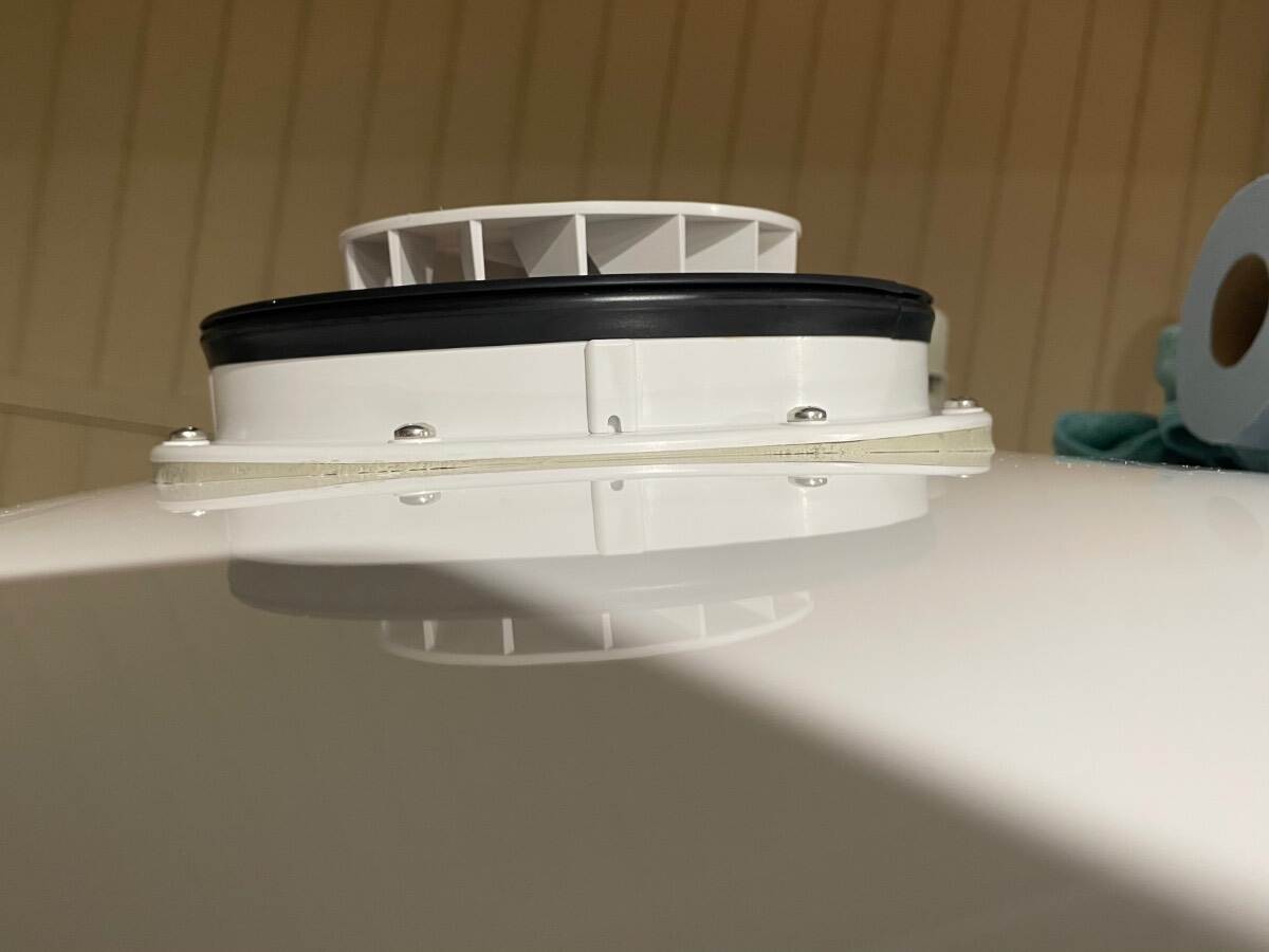
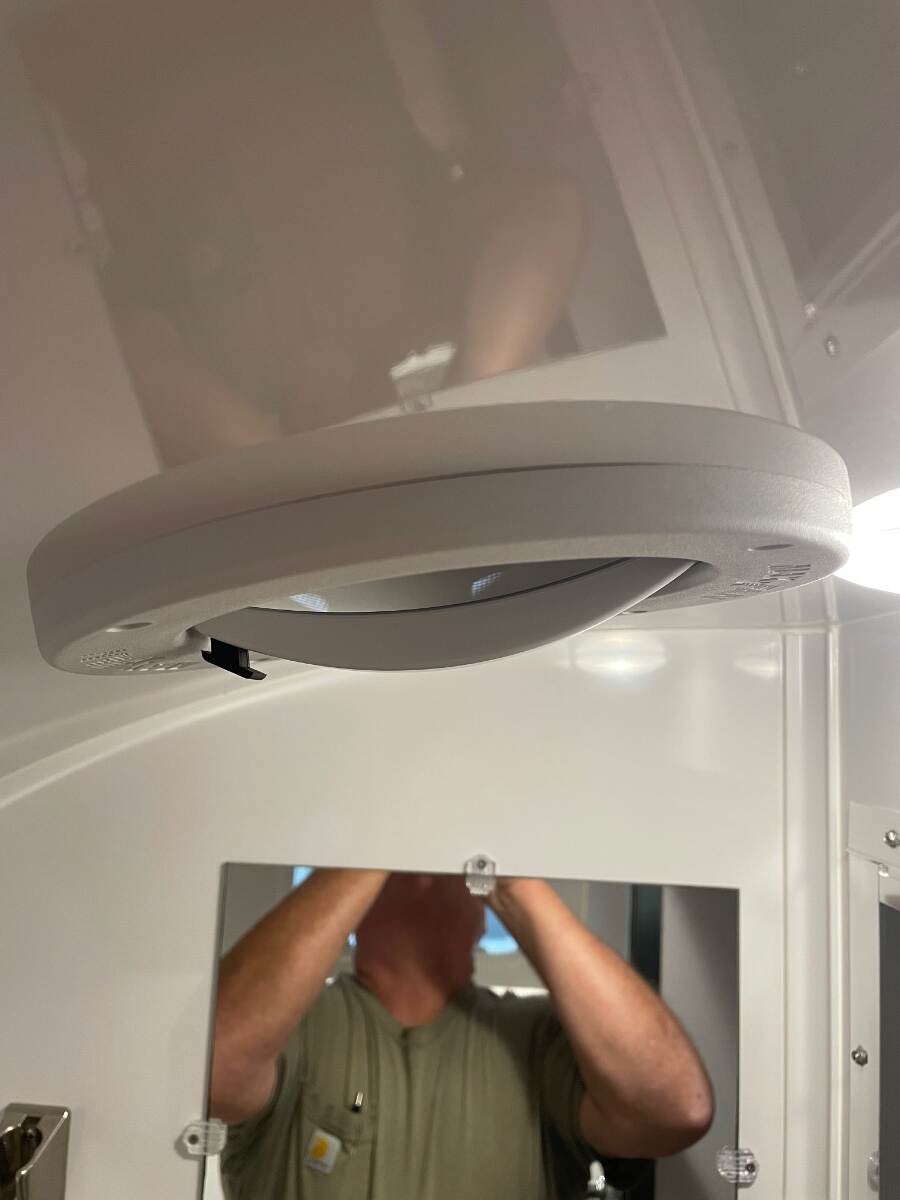
With the inside work complete I went back to the roof area, trimmed the oozed butyl, wiped with isopropyl alcohol again, and taped off the area to be caulked leaving about a quarter inch gap from the edge of the flange in the front and rear and about an 1/8 inch gap on the sides where the caulk would be the shortest. I applied the caulk 3 times, wiping it off the first two times, reapplying the tape and recaulking each time because I didn’t like the way it looked. I finally left it alone because I decided that if I kept messing with it I would keep screwing it up and it was close to supper time and I was starting to get hungry. This picture shows the fan after the oozed butyl was trimmed back. It shows the built-up butyl in front of and behind the fan to keep the flange straight. This next picture is after the ASI 335 was applied. Notice that the black seal is straight, not bowed down at the front and rear due to having the flange pulled down to touch the roof. The black seal must remain straight so that the cover will seal properly when closed. I applied the ASI 335 to the screws but didn’t like the way they looked so I wiped it off. I had applied ASI 335 to the screw holes and the screws were twisted in through up to 3 layers of butyl so I figured they were sealed well enough. The caulk job wasn’t perfect but it looks good from the ground. The ripples are from my hand shaking after going through the process 3 times before finally accepting that it wasn’t going to be perfect. I actually like the stepped edge of the caulk versus a feathered edge because I think the feathered edge of caulk doesn’t hold up well after repeated washing, drying, and waxing. We’ve pulled the trailer through wind and rain for 1350 miles and it has remained closed and hasn’t leaked. I can’t completely say that it is quieter than the original Ventline fan but it does not have the rattle that it did. ASI 0240 https://meridianadhesives.com/products/asi-0240/ ASI 335 https://meridianadhesives.com/products/?product_search=335 It looks like ASI has two versions of the 335. The stuff I used looked like this Good luck on your installation. Bill
-
Maxxfan Dome installation (previously orientation)
Townesw replied to Townesw's topic in Ollie Modifications
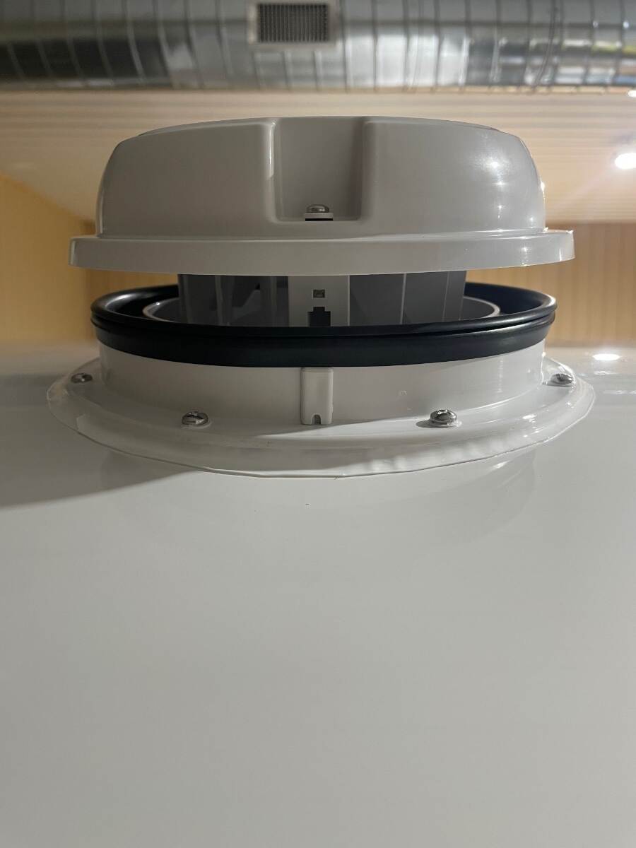
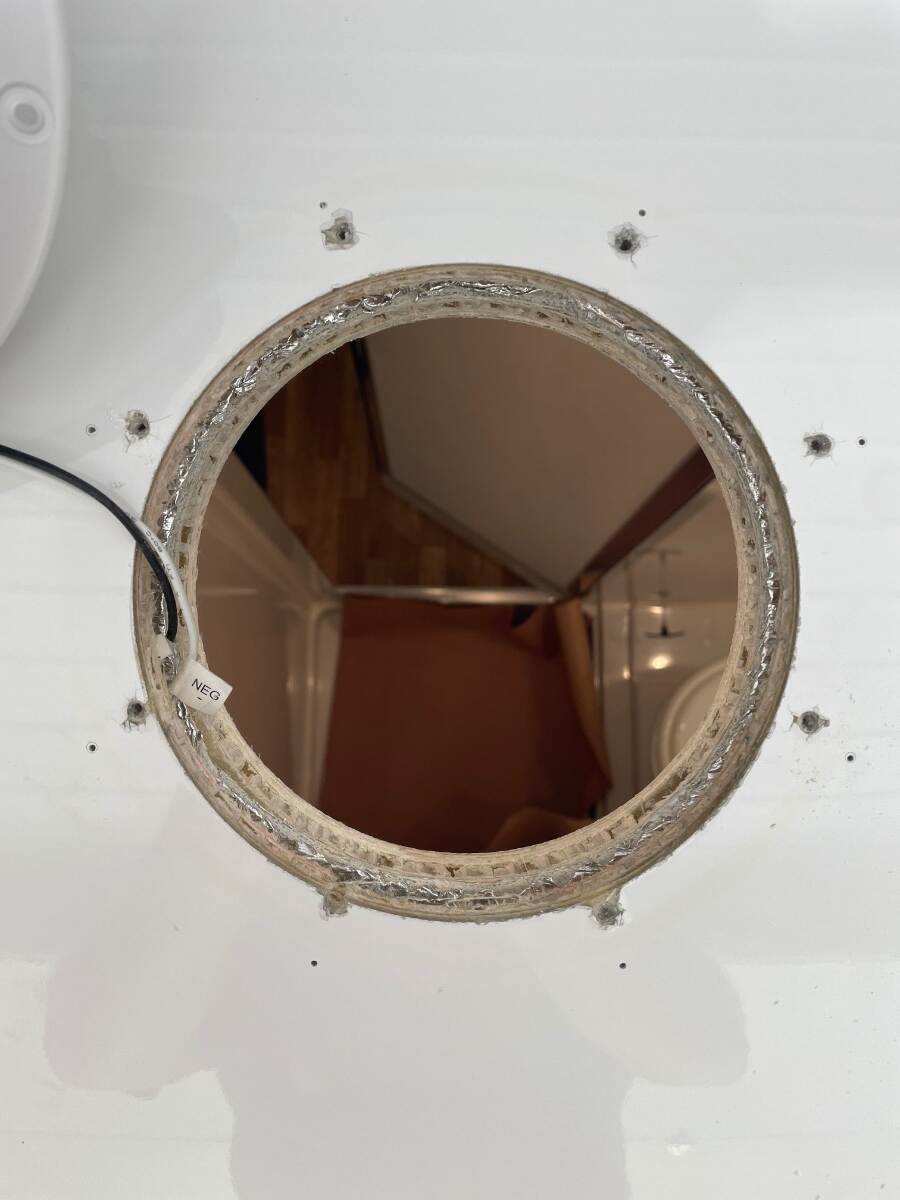
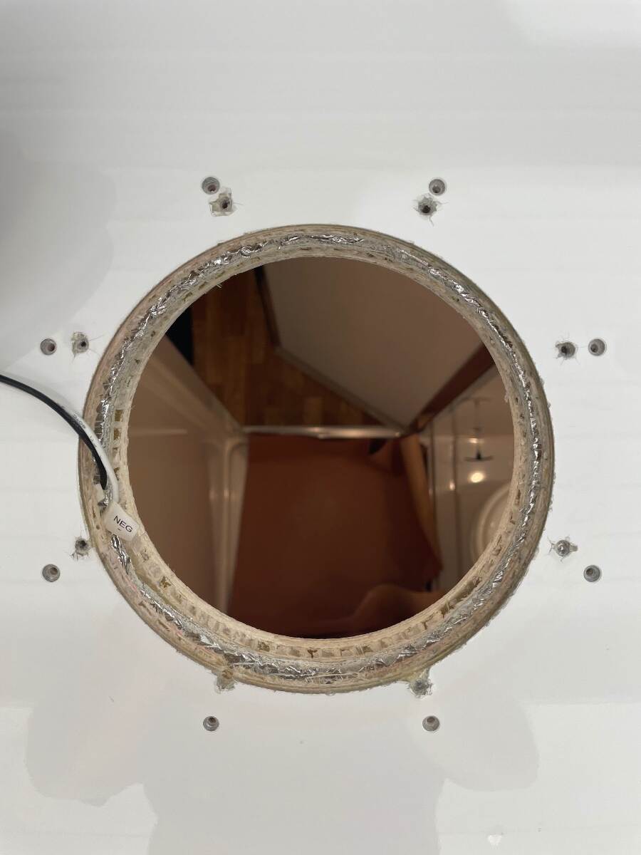
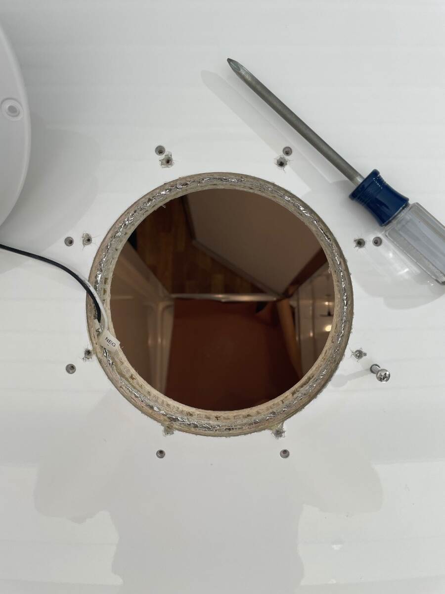
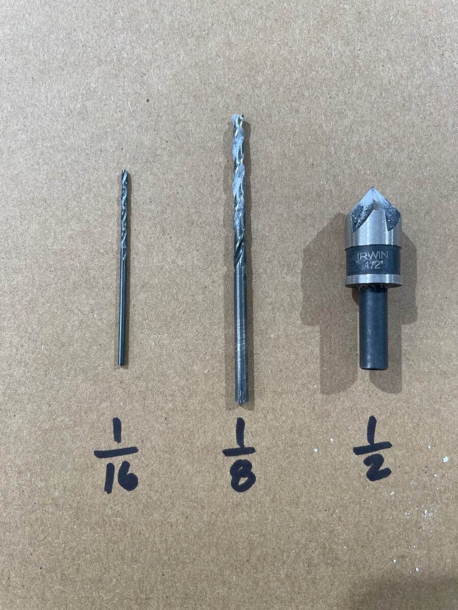
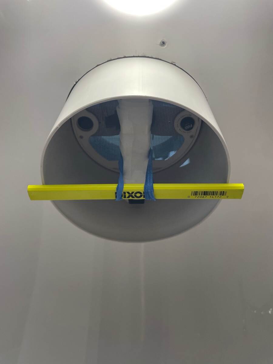
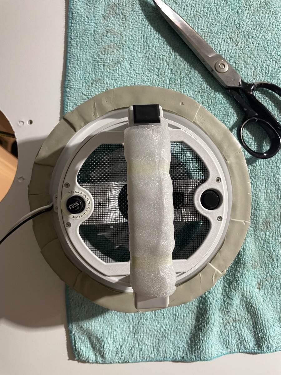
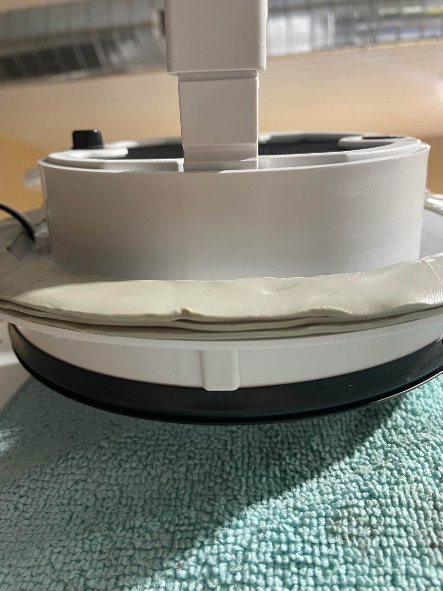
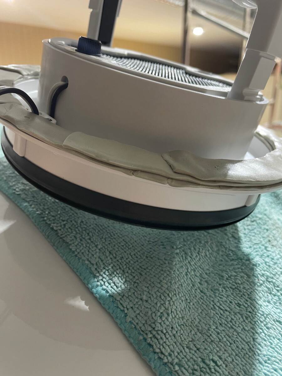
Picture below shows old Ventline fan removed and the roof area cleaned up. I used ASI 0240 adhesive remover and plastic razor blades. I cleaned up the edges of the original holes with a chamfer bit in a drill motor. The factory didn’t align the old vent with the hole very well resulting in screw holes too close to the edge of the opening and didn’t drill and chamfer the holes which resulted in chipped gelcoat. In this picture the pilot holes (1/16”) for MaxxFan Dome are located and drilled. I wanted the screws to be perpendicular to the MaxxFan mounting flange not the roof line so I tried to drill them at the correct angle to the surface of the roof. I did a lot of test fitting inside and out. The outside fan, the middle sleeve, and the interior trim ring must fit together well for this retrofit to work out right. I used a carpenter’s pencil and 2 rubber bands from of a bunch of broccoli to hold the sleeve in place while I got the pieces located just right. I did this before I marked the holes for the flange. New pilot holes are enlarged to 1/8 inch and chamfered Test fit the screws to make sure they are not too tight. If they are too tight you risk twisting the screw in two in the hole. This would be bad. Very bad. If the test fit is too tight go up to 9/64 inch bit. I used a 1/16 inch drill for a pilot then enlarged with a 1/8 inch drill and finished with a 1/2 inch chamfer bit. Be sure to use sharp bits and drill SLOW. I wanted the flange to be straight, not pulled down to fit the curved roof. I applied one layer of butyl all the way around the bottom of the flange. I then applied 2 short strips between about 10:00-2:00 and 4:00- 8:00. I again applied 2 even shorter strips between 10:30-1:30 and 4:30-7:30. I tried to build the butyl up in the places where the widest gaps would occur, that is the front and back of the fan. I wiped the mounting location with isopropyl alcohol and let it dry and filled the old and new screw holes with ASI 335 and set the fan in place using a couple of screws inserted through the flange and butyl for alignment. The black button on the handle goes toward the front of the trailer. Work the wires and splice connectors into the space between the hulls while inserting the fan assembly into the hole in the roof. Go back inside the bathroom and put the sleeve, pencil, and broccoli rubber bands in place to help maintain alignment of the fan on the roof. Back on top, tighten each screw down a little at a time and try to keep from distorting the flange. I would tighten the screws and leave them for a while to let the butyl push out then I would tighten them a little more until I got the flange sitting like I wanted it to sit and then left the butyl to do what it wanted to for a while. While the butyl was oozing I went inside the trailer and made sure the sleeve was in place with the upper edge of the sleeve against the bottom of the fan and the notch in the sleeve for the wire retainer properly located. Using a pencil I marked a line around the sleeve where it exits the curved ceiling. I drew another line 0.35” below this line to account for the interior trim ring and cut the sleeve to this line using a pair of heavy shears and a razor knife and finished to fit with a sanding block. I attached the trim ring and tightened the screws enough to pull the ring up to conform to the curvature of the ceiling.
-
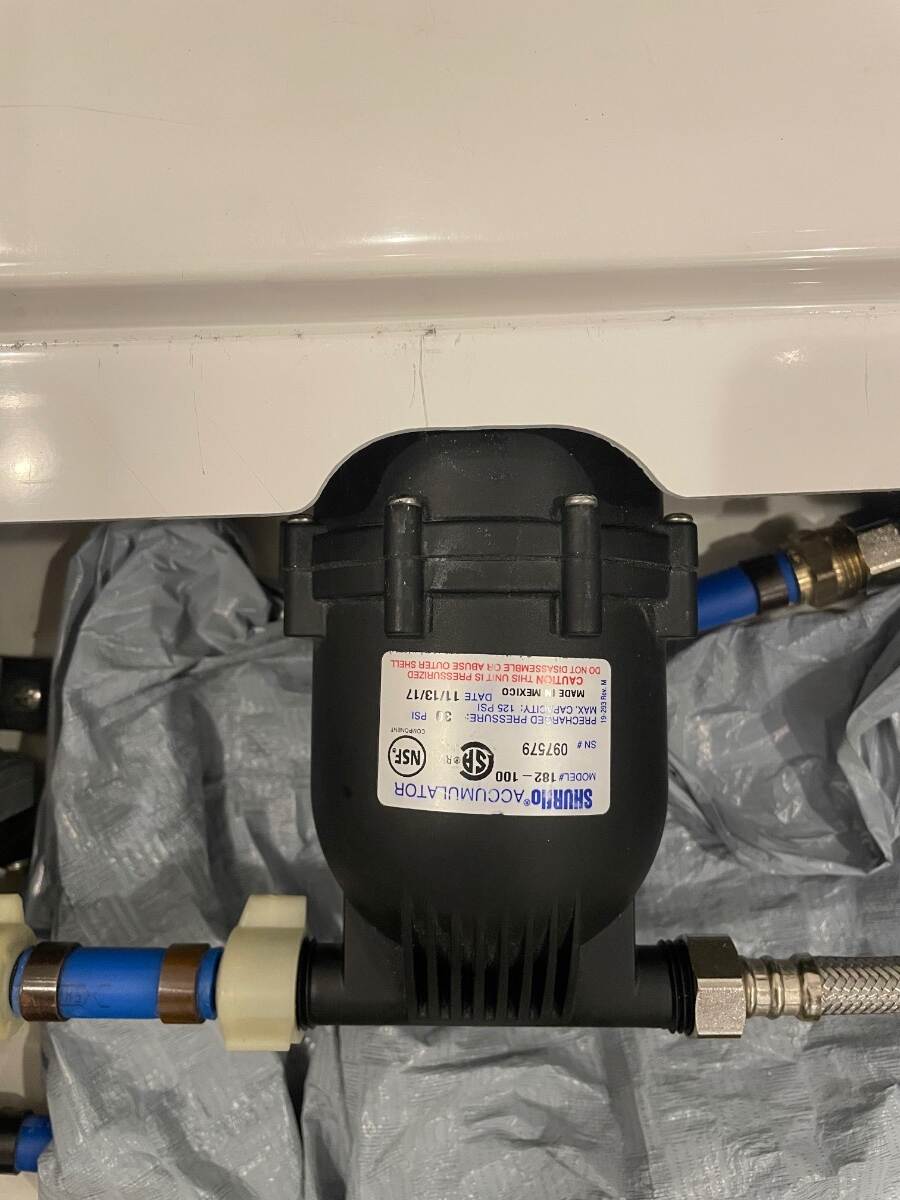
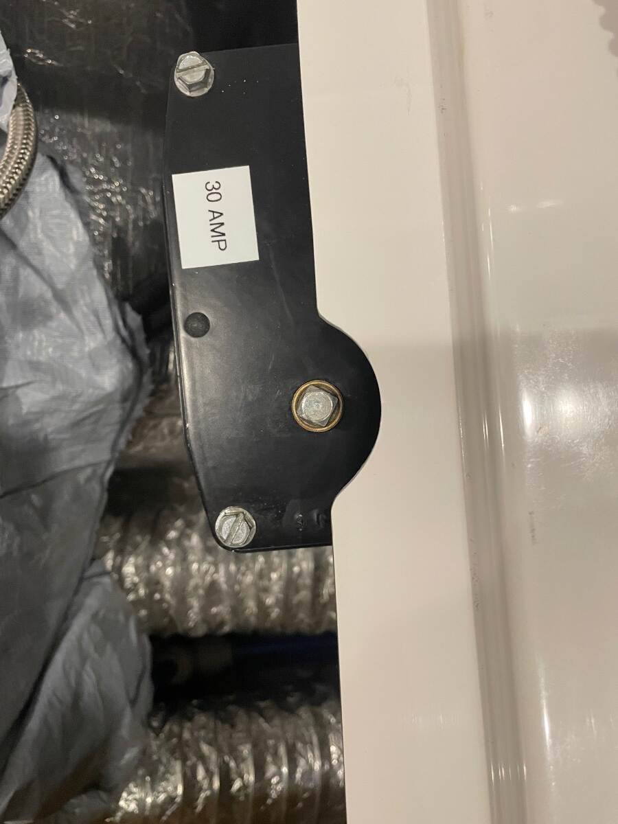
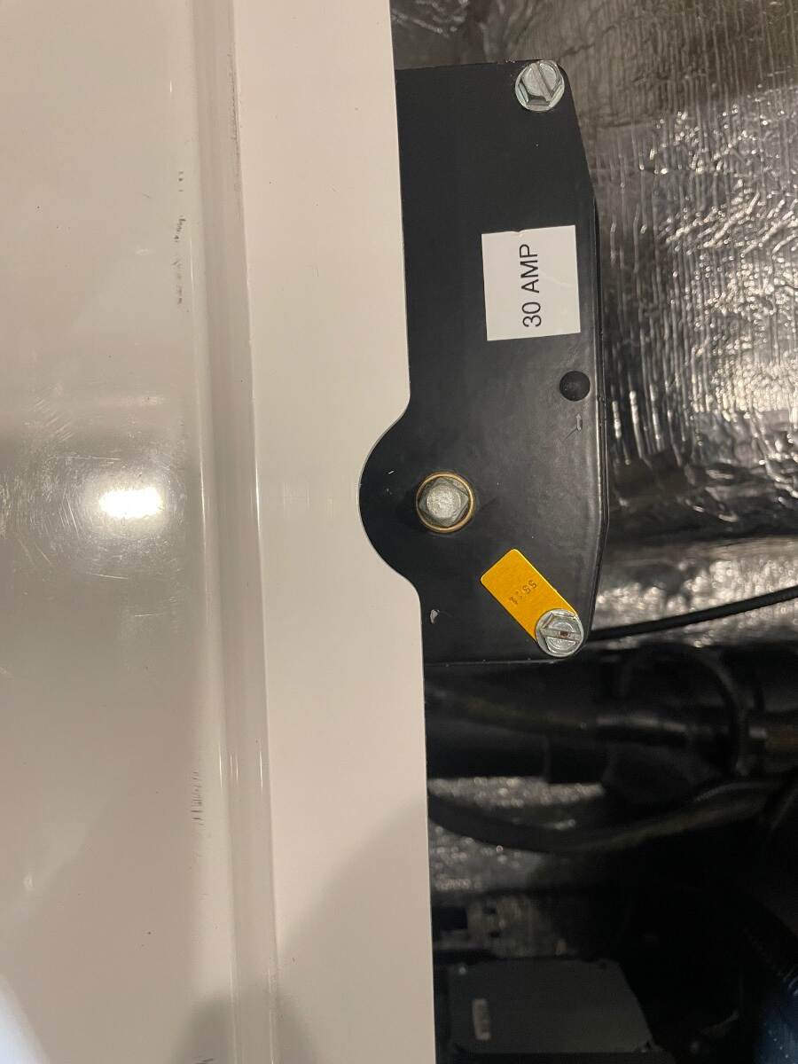
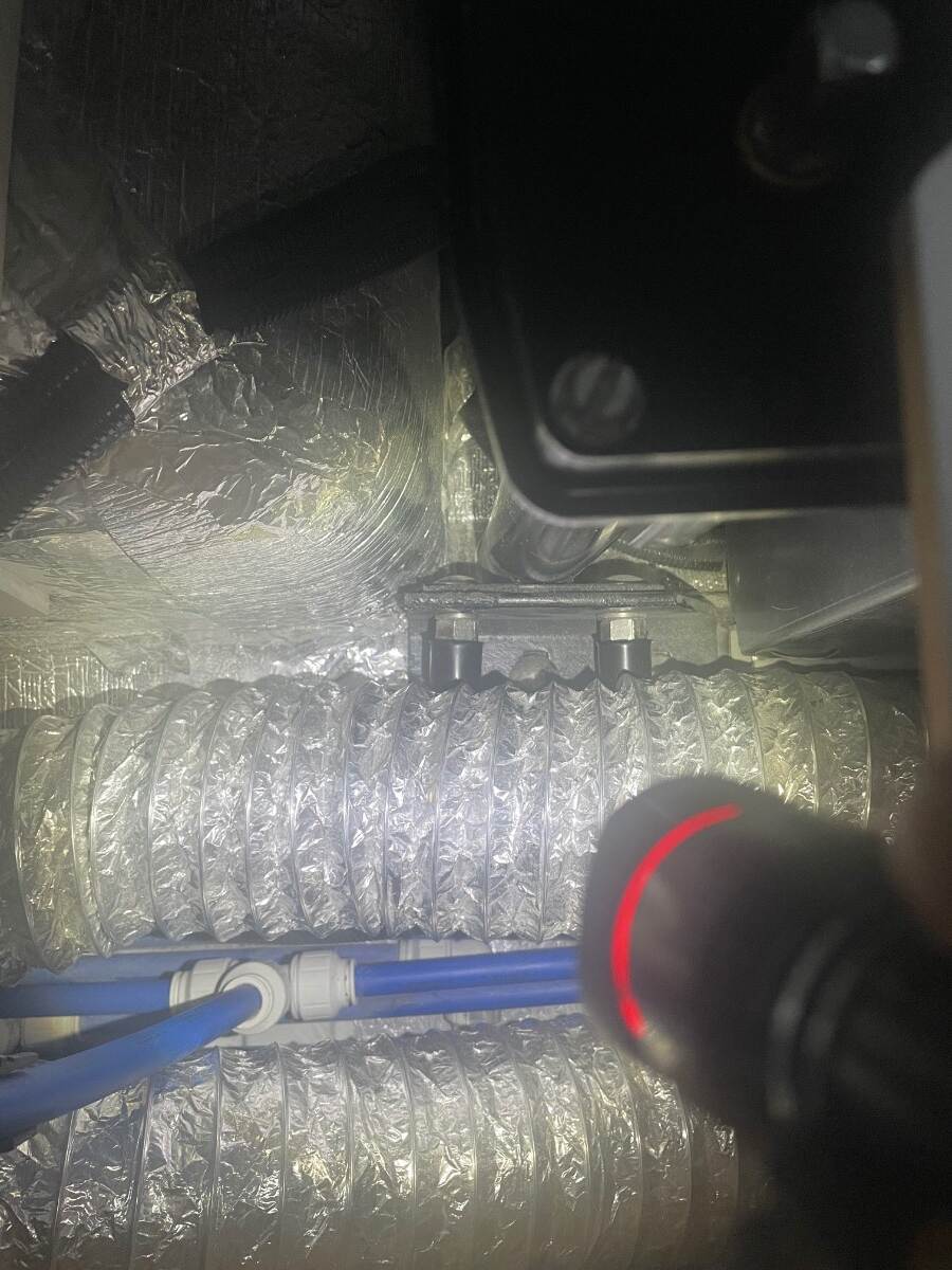
UPDATED : Check your accumulator and other stuff
Townesw replied to Townesw's topic in Mechanical & Technical Tips
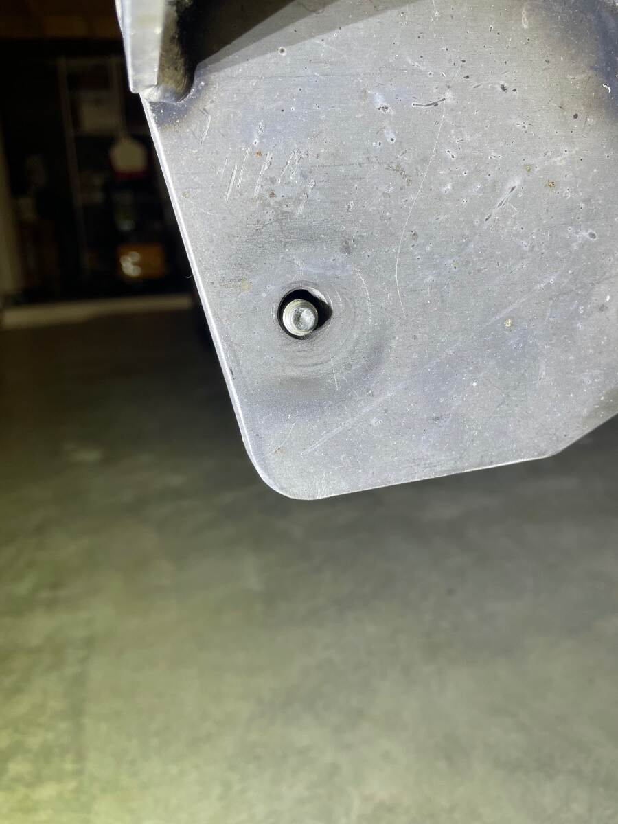
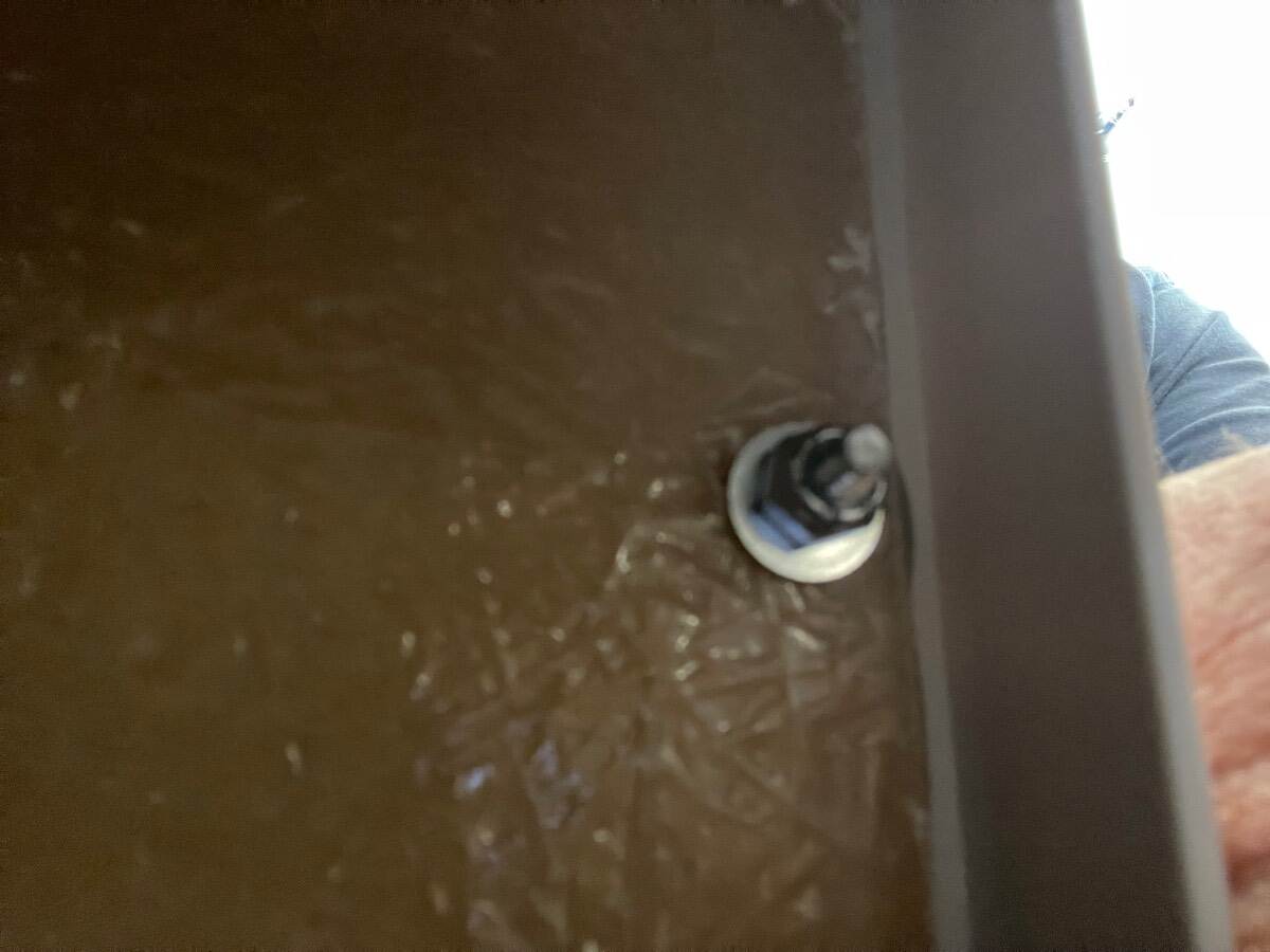
Finally got around to fixing the problems that I identified in my original post almost 2 years ago. I used a small drum sander on a cordless drill motor to make a cutout for the part of the accumulator that was rubbing. This also quieted a vibration heard during pump operation While I had the drum sander out I enlarged the cutouts above both rear jack manual operation studs so that I can now get the manual crank on them if needed I placed a couple of spare bolt protectors on some 1/2 inch nuts and threaded them on the exposed bolt ends where they contacted the heater duct I know that these are really simple fixes but they might help someone that doesn’t know that the problems even exist. Bill
-
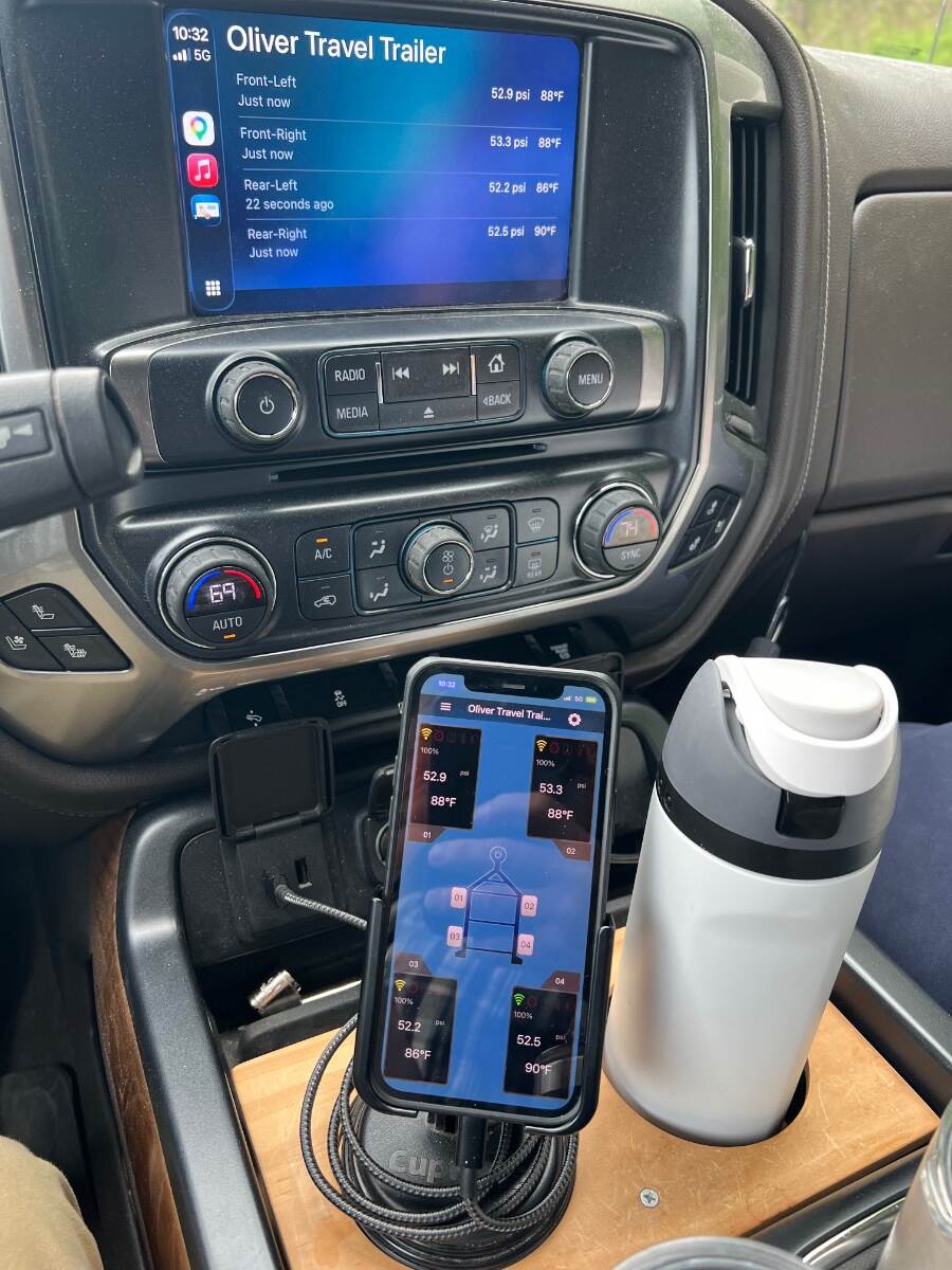
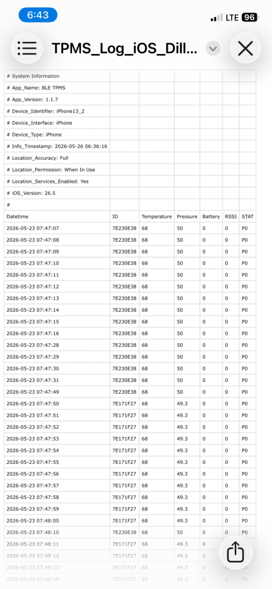
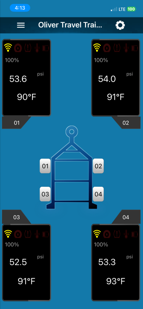
Update to my original post I replaced my original Dill TPMS system with the new Dill Bluetooth TPMS system and have used it for the last 3 days. These sensors are internally mounted just like the sensors on your truck and automobile tires. My truck doesn’t have the required RPO necessary to receive the sensor signals but the output is displayed on my truck infotainment screen when my phone is plugged in. I usually keep my phone display on the Dill app and keep Google Maps displayed on the infotainment screen but here is a picture that shows the Dill output on both screens You can download the data from the sensors into Excel. Dill recommends that you use a BLE signal repeater to extend the signal to your phone. I am trying different locations for the repeater but for now I have it on the left rear corner of the dinette and plugged into the 12v accessory receptacle under the dinette. I attached the 12v accessory plug to the repeater wires. I am getting 100% signal reception with the repeater located here. Signal reception is noted on the app display. I really like this version of Dill’s TPMS system compared to the older version that I used from 2019-2025.
-
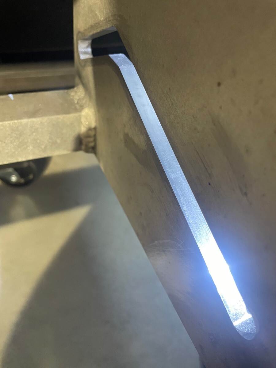
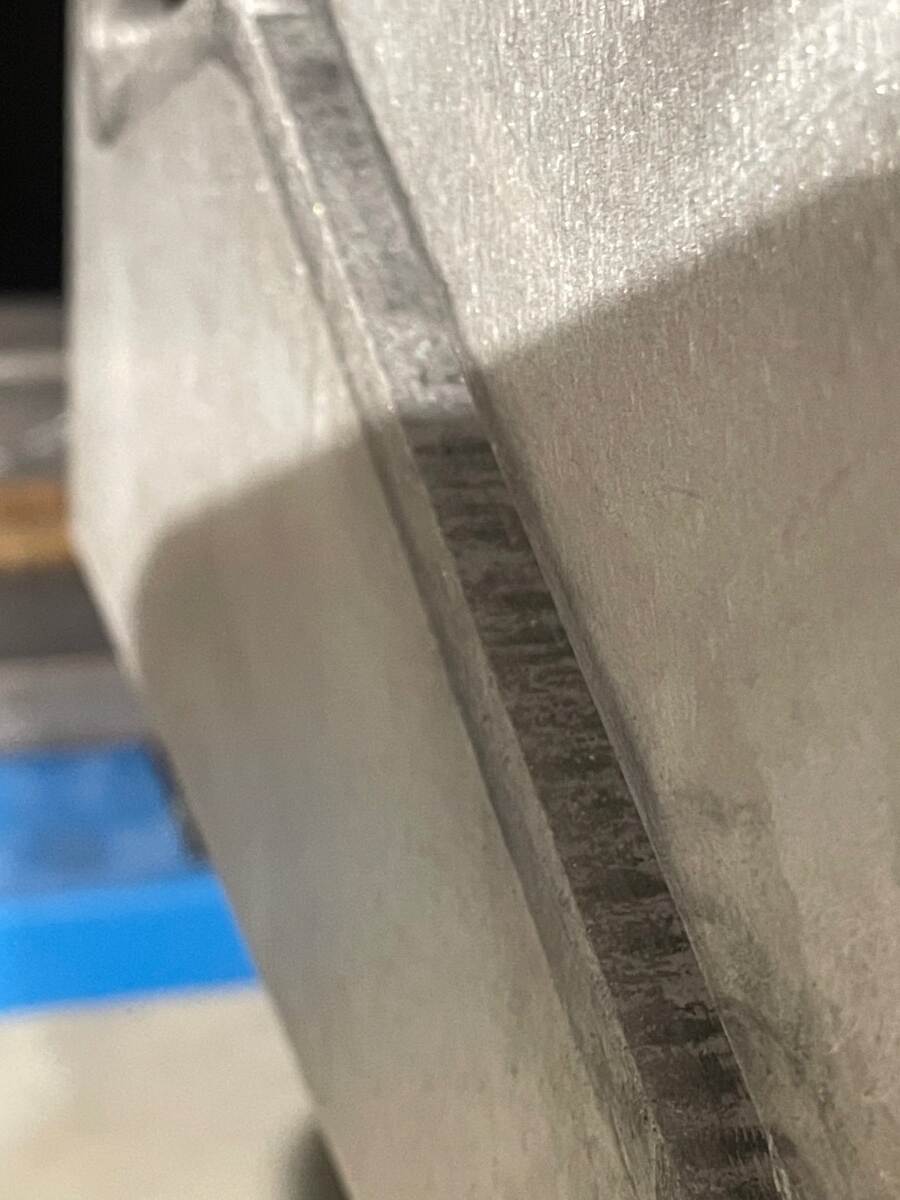
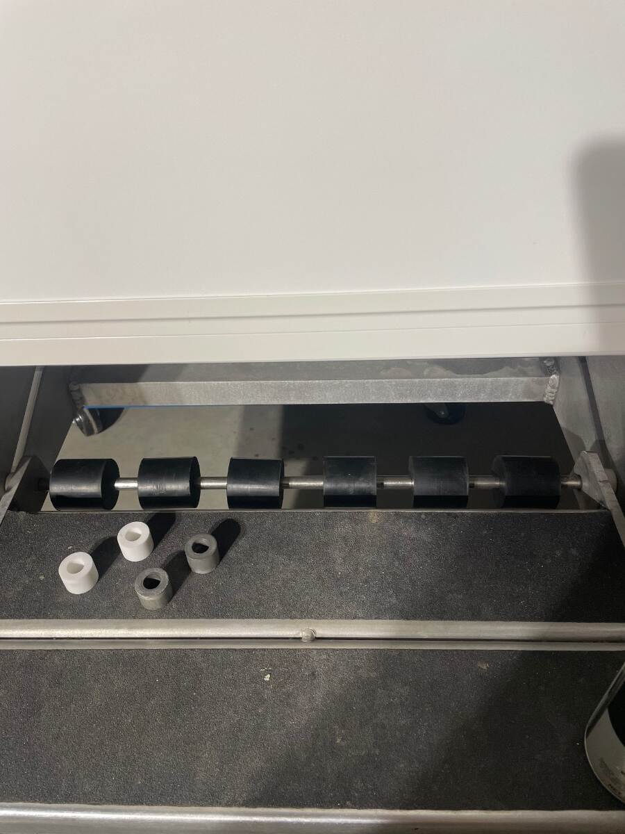
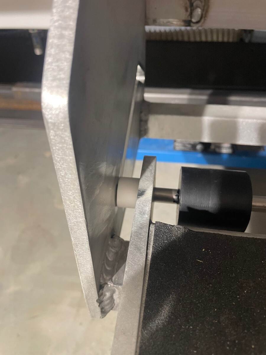
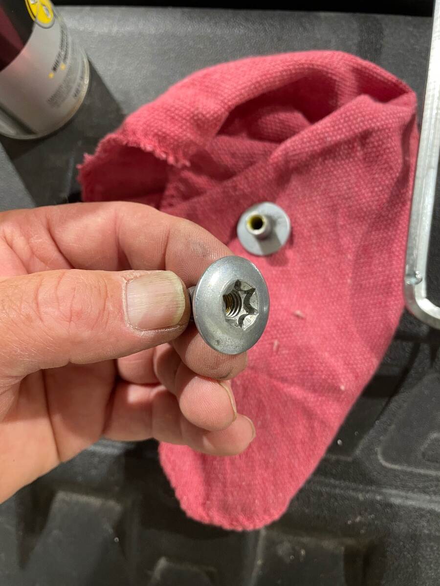
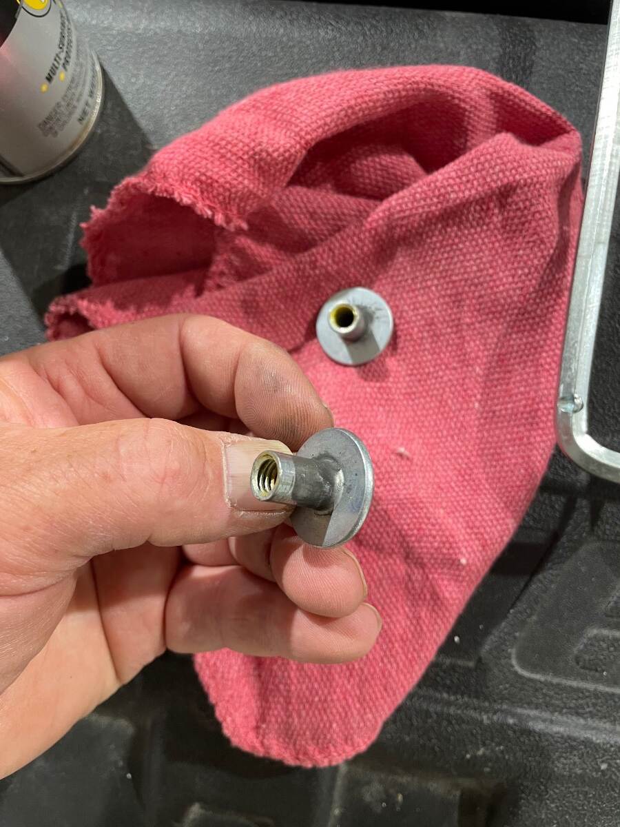
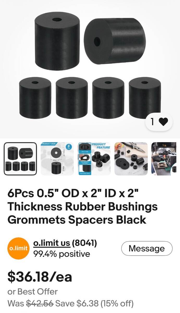
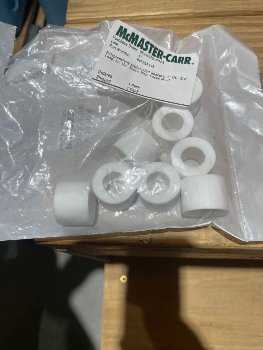
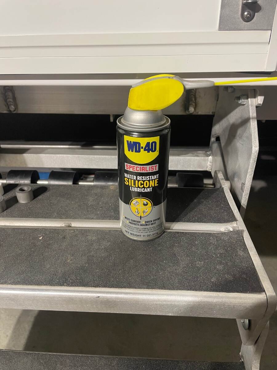
The steps on our Oliver have always been loud when being lowered or raised. I have taken some “steps” that have made them quieter. And before you ask, no, I don’t have before and after noise level analytical data. I just know that they are quieter. 1. I draw filed the top and bottom of both slots. This picture after a couple of draw passes with a file shows the roughness left by the machining process. The bright spots are the high spots of the rough surface. I suspect that one side of the slot was smoother than the other due to the direction of rotation of the cutting tool. Picture of the bottom of the right side slot after several passes using a draw file technique. Be sure to keep the swarf cleaned out of the file. There is a light shining on the surface. It is much smoother. I then applied some silicone lubricant to both sides of each slot and allowed it to dry. 2. I next reassembled the steps and placed (6) rubber bushings on the stainless steel rod to dampen the vibrations that the rod made when being drawn through the slot in the aluminum sides. 3. I also replaced the aluminum spacers on each side with polypropylene spacers. 4. I removed the female halves of the sex bolts that act as the pivot for the lower step. I used a T50 torx bit but it is actually a T55. I have the correct bit now. Never pass up the chance to buy a new tool. I applied silicone lubricant to the inside of the hole in the step side and to the outside of the binding barrel and allowed it to dry before reassembling. I will probably drill those holes out to receive Oilite bushings this winter but this will suffice for now. Material used. The rubber bushings are actually 1/2” ID x 2” OD x 2” long. The holes aren’t perfectly centered but I didn’t need for them to be. I chose 2” OD so that they would clear other parts of the step assembly. You will have to lubricate the step rod and the hole in the bushings to be able to assemble them. The polypropylene spacers came from McMaster Carr. Be sure to use a dry silicone lubricant instead of grease. The grease will retain grit picked up off the road. Bill
- 1 reply
-
- 8
-

-

-
I have thought about putting the switch and LED between the TP holder and the air duct. Bill
-
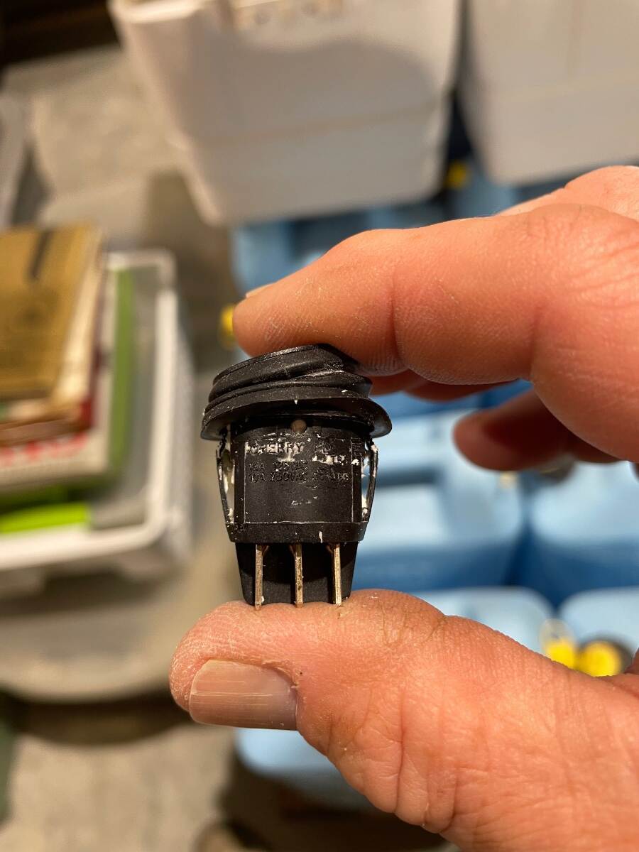
That is why I want to use a threaded body switch. I see that you have run into this problem also. I have used panel mounted switches in thick material by finding a hose that the switch will fit tightly into, cutting a short ring out of the hose, and then slipping the ring over the back of the switch to hold it in place, sort of like threading a nut on. I have found an adapter to mount a panel mount using a threaded bushing. I had rather use a threaded switch but I may have to use this
-
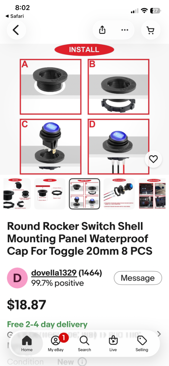
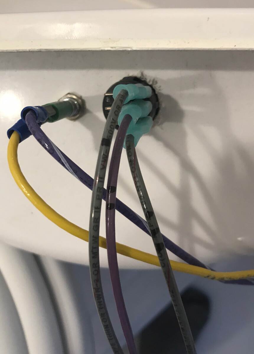
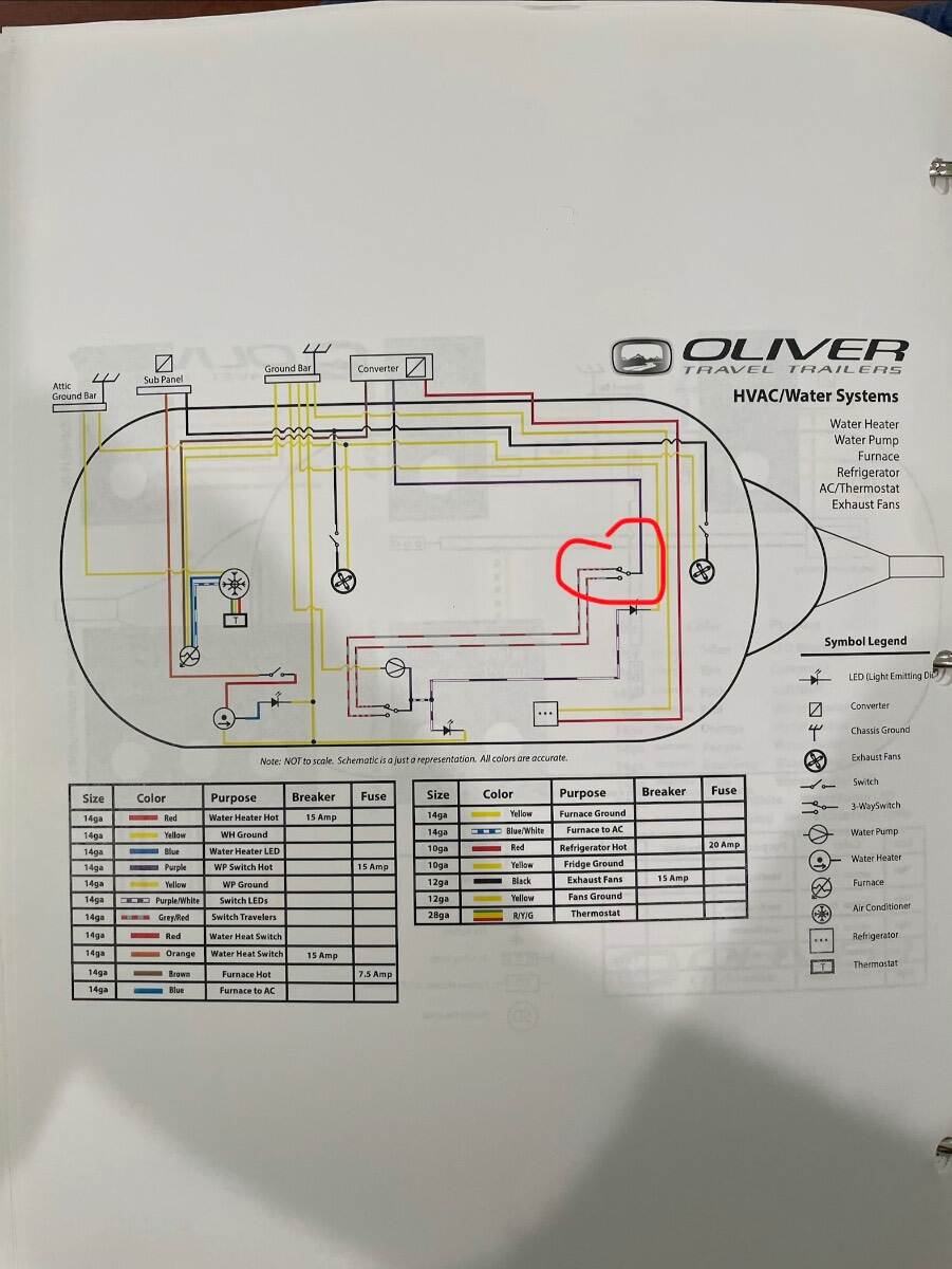
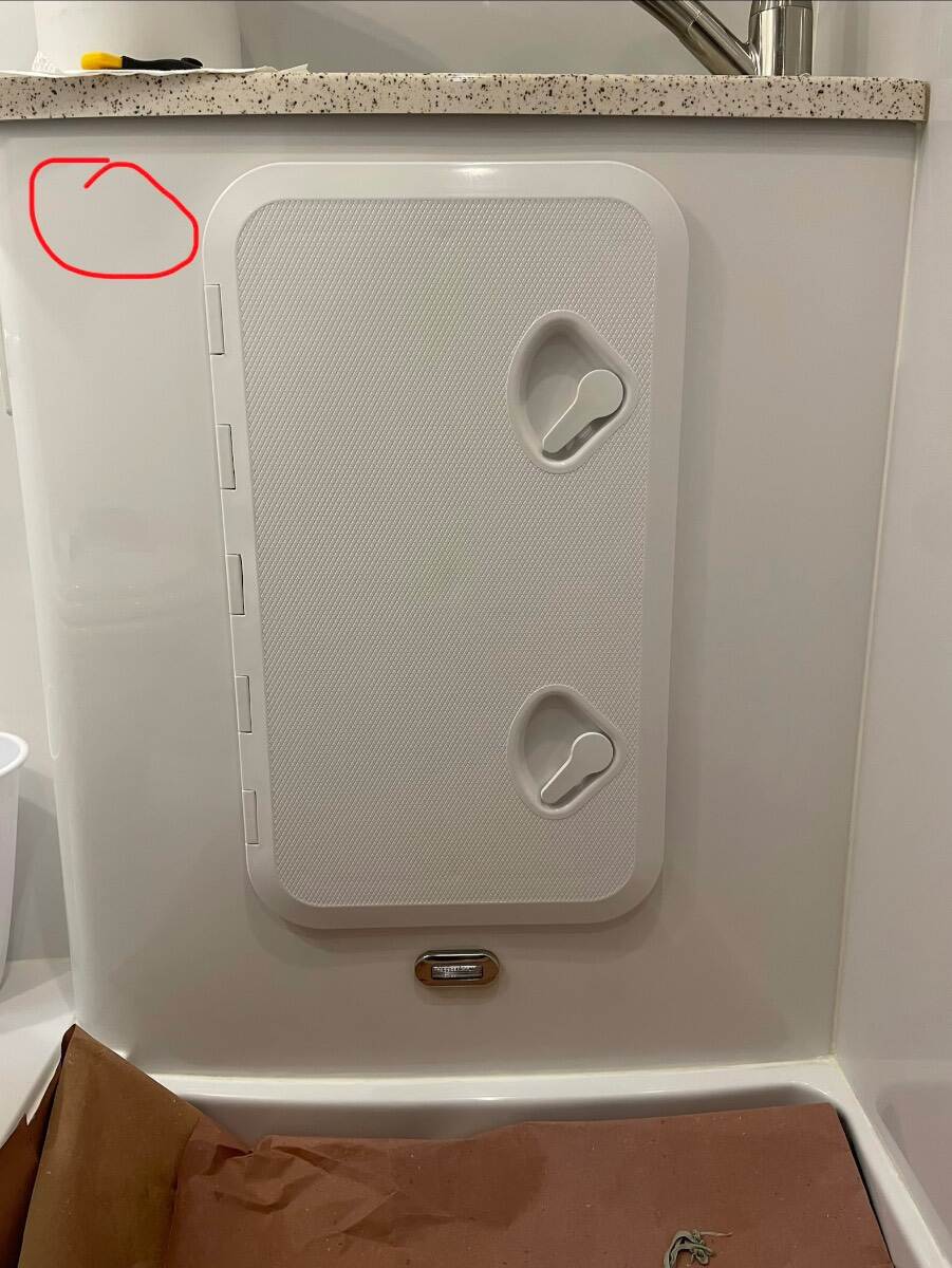
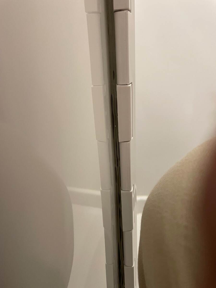
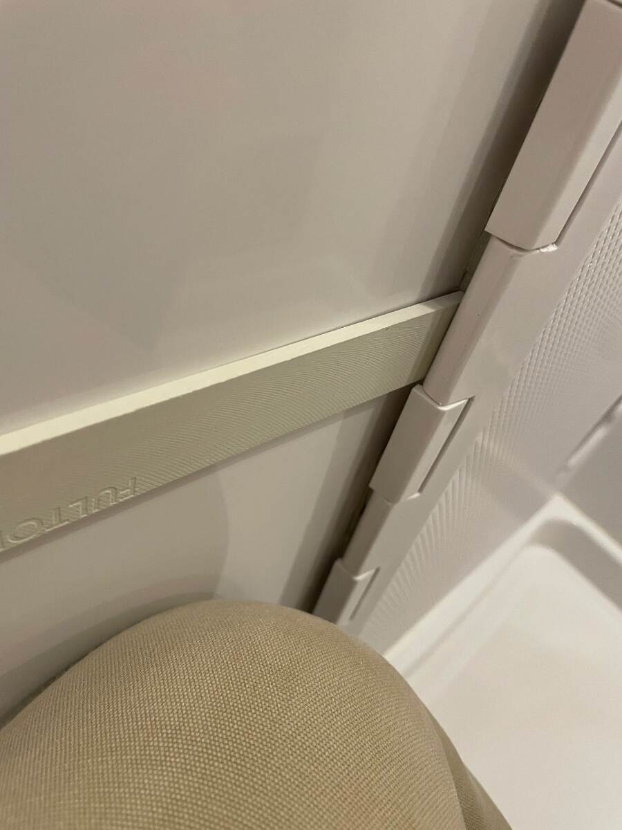
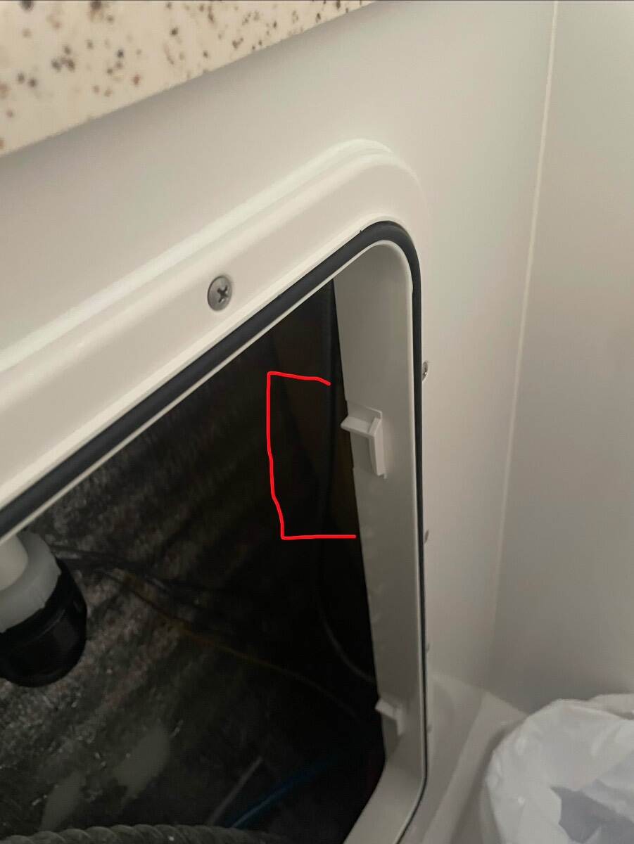
I am looking for a round rocker switch, SPDT, weatherproof, threaded mount, not lighted, blade terminals. I am not finding anything like this using my usual search methods. I have removed the shelf from the bathroom vanity and have installed a marine hatch in its place. I now must relocate the pump switch. The factory used what I think is a DPDT panel mount switch and held it in place with a wad of caulk. I want to mount the switch more securely. Switch as mounted in the shower shelf Switch removed from shower shelf Where I want to place a new switch Wiring schematic showing switch I want to replace Thanks for your help Bill
-
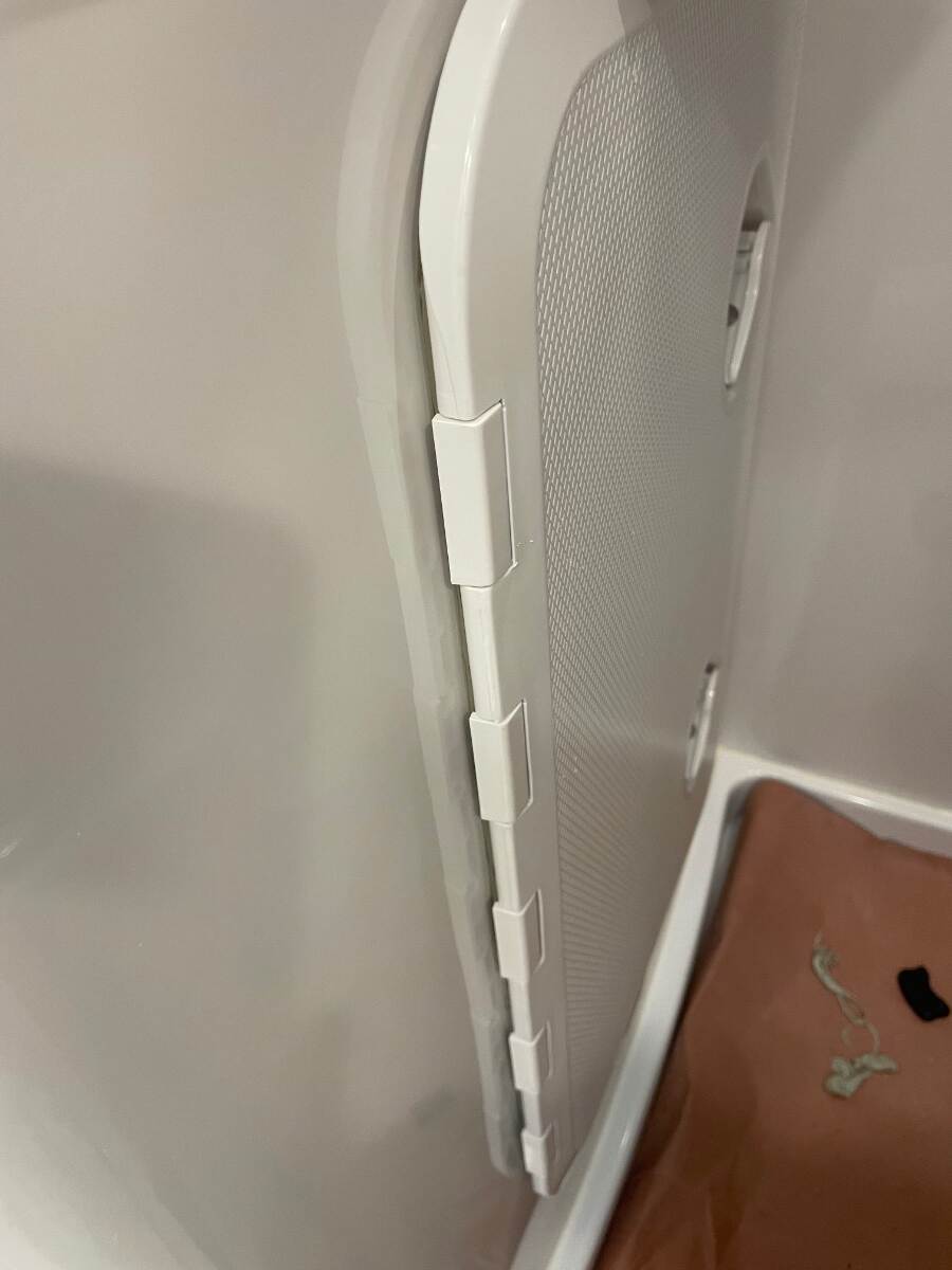
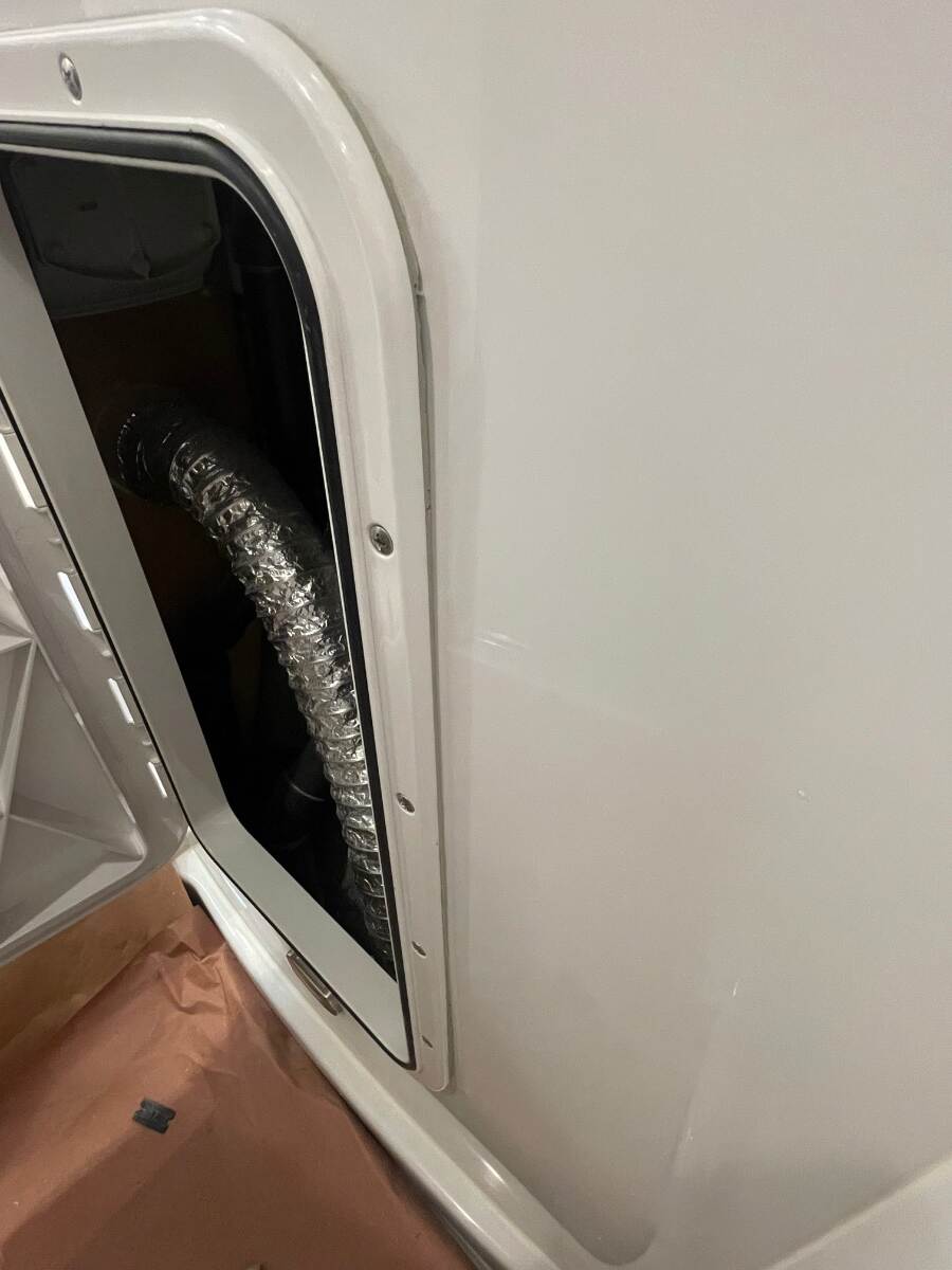
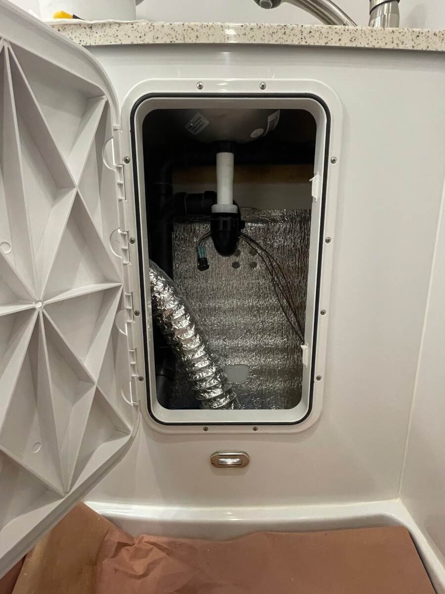
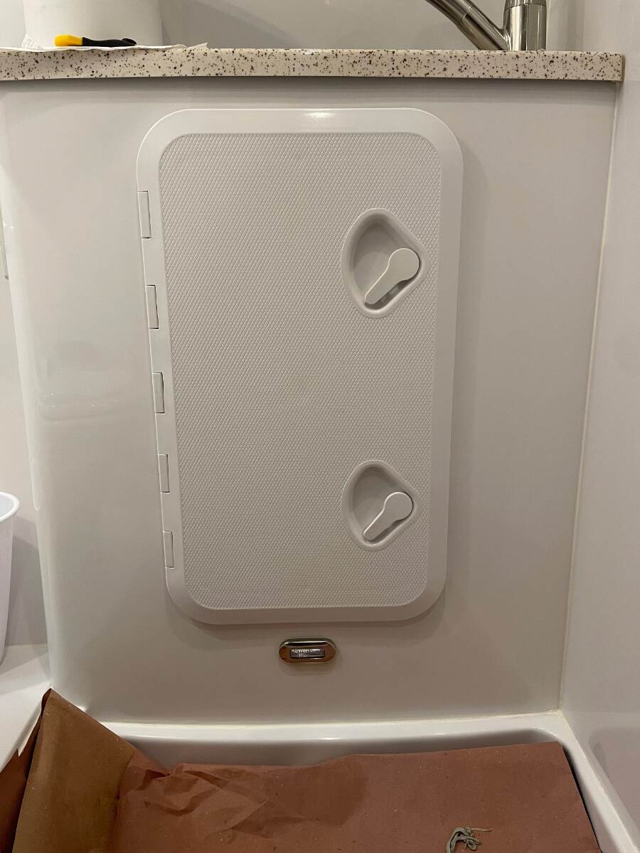
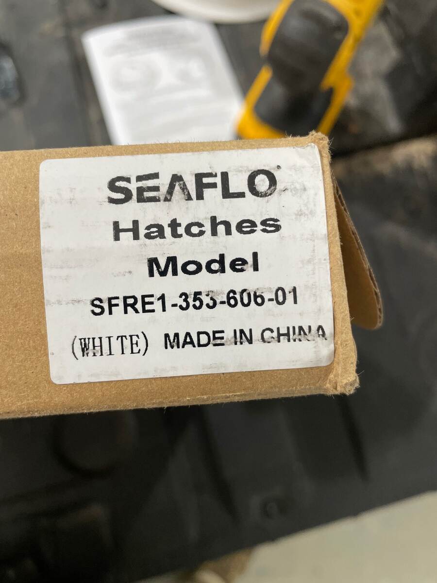
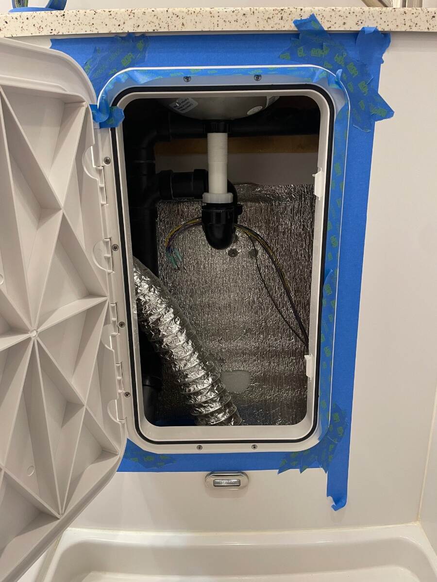
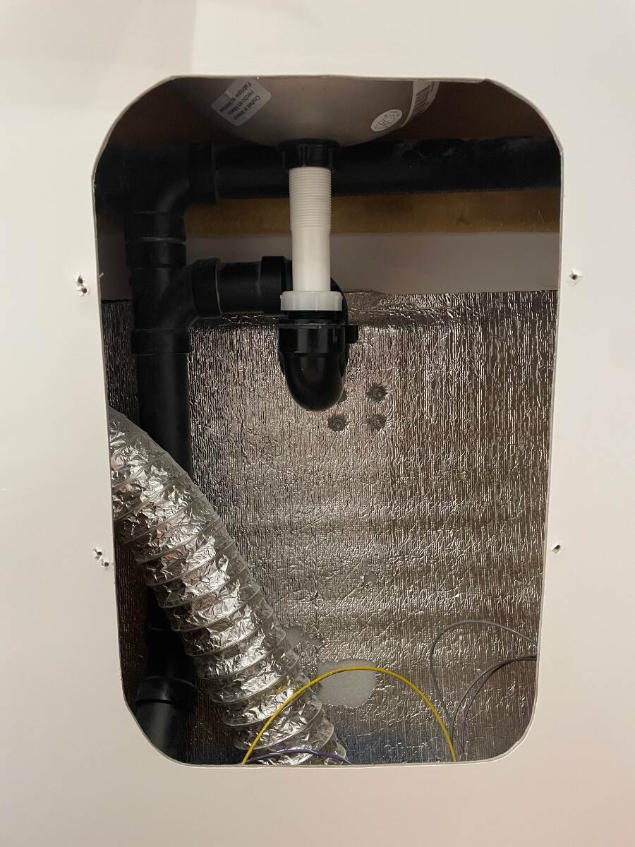
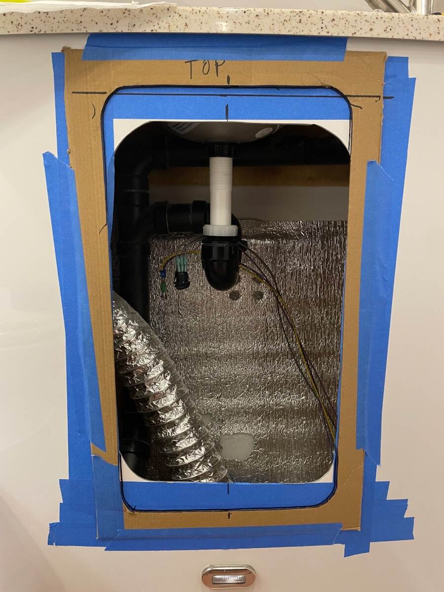
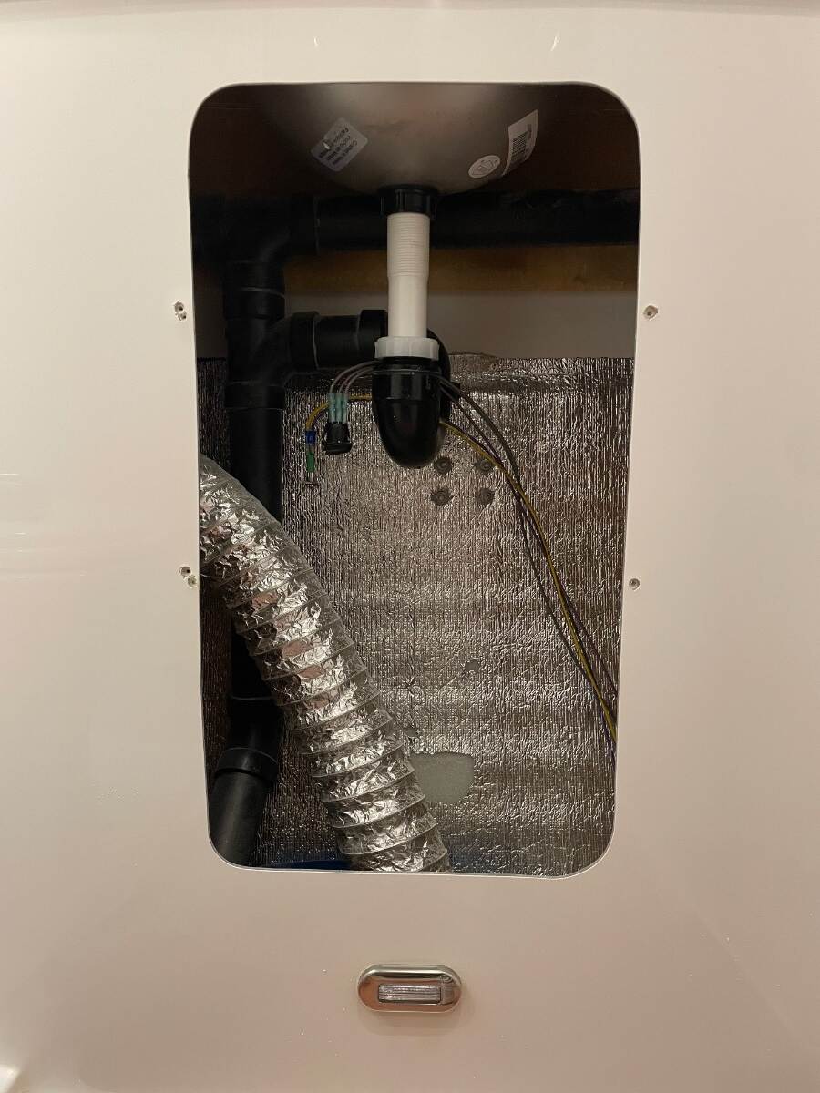
I have been wanting to do this modification for a few years now and actually bought the hatch a few years ago but just got around to installing it before this recent trip. I never have liked the shower caddy/shelf in the bathroom vanity. I’ve had it out at least 2 times to work on the faucet and to replace the sink drainpipe. I needed to tighten the nuts on the bolts that go through the propane enclosure and are accessible only under the sink so I took the opportunity to install the marine hatch. Picture of caddy removed and cleaned up using ASI 0240 adhesive remover and plastic razor blades. I never have cared for the way the factory drills holes in the gelcoat. Every factory screw hole I have seen has cracked gelcoat around it. Vanity front taped up and template taped in place. I actually lowered it after this picture was taken. The door doesn’t detach from the flange, and even if it did you couldn’t reassemble it after the flange was mounted. This and the small space that you are working in makes the hatch and flange difficult to position accurately. It helps to make the opening just large enough for the flange to fit into, then you can modify the hole if needed to square up the hatch. I used a coping saw to cut the fiberglass and a sanding drum in a drill to shape the hole. I cut the opening a little small at first but it was easy to open up a bit using the sanding drum and a sanding block. I marked and drilled pilot holes, then screw-sized holes, then chamfered the screw holes with a 1/2 inch chamfer bit. I also cleaned up the factory holes using my chamfer bit. You’ll want to locate and drill 2 holes, one on each vertical side, then temporarily mount the hatch so that you can better mark the remaining holes. Holes not shown in this picture. I placed one layer of butyl tape all around the flange then an additional layer of butyl along the vertical sides. I did this because the front of the vanity has a slight curve and I didn’t want to pull the vertical sides down to meet the vanity surface. I used 10-24 x 1inch stainless steel oval head machine screws, #12 stainless steel flat washers (because that what I had), and 10-24 Stainless steel Nylock nuts to secure the flange to the vanity. Picture after the butyl is through oozing and trimmed flush with the flange. You can’t trim the butyl behind the hinge so be careful how you apply it to the back of the flange on the hinge side. I suggest keeping it back away from the edge 1/16” and hopefully it will extrude evenly as you tighten the machine screws. I’ll talk more about this area later. Taped off for caulking with ASI 335 sealant You can’t caulk the edge behind the hinge. I wasn’t pleased with the way the butyl looked behind the hinge… …So I used a paint stirring stick that had dried latex paint on it (this sealed the end grain of the stick) to “tool” the butyl behind the hinge. This produced a finish that I was pleased with Picture of open hatch. I have yet to relocate the pump switch and light. I am thinking about putting them in a stainless steel bracket just inside the top right of the opening so that the switch can be accessed while seated. Notice the pump switch and light hanging over the p-trap. I’ve got it cable tied there for this trip. Marine hatch used. I think I ordered it off Amazon. I am very pleased with the way this modification turned out and being able to very easily access the area below the sink. I don’t intend to store anything under the sink, I just like being able to see in as many places as possible. Again, apologies to any of my High School English teachers who may be reading this. Bill
-
Maxxfan Dome installation (previously orientation)
Townesw replied to Townesw's topic in Ollie Modifications
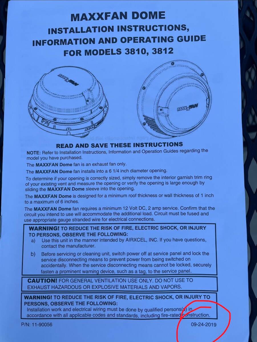
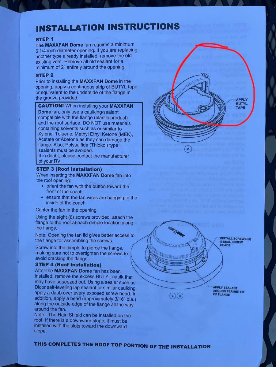
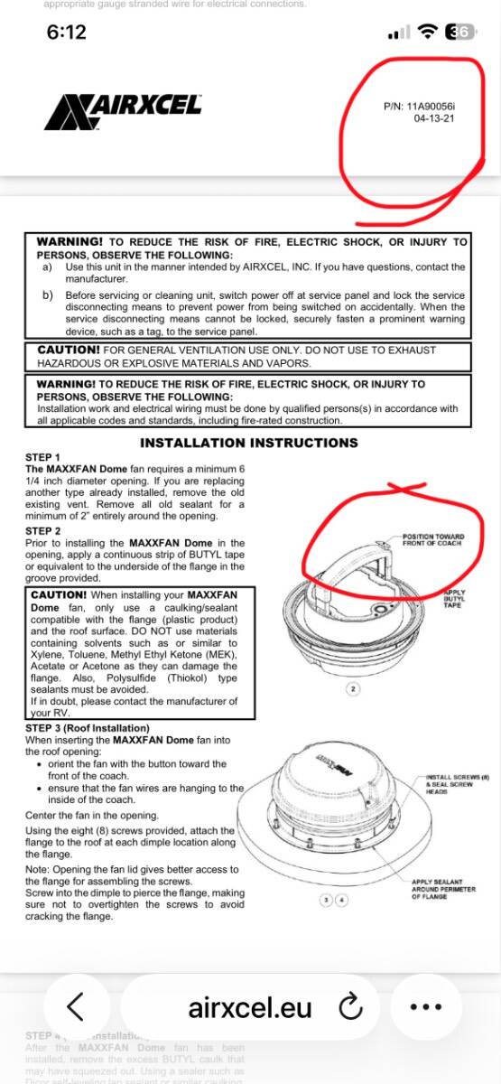
Thanks for your responses. I found a newer version of the installation instructions online. My installation instructions dated 09-24-2019 do not have the note on the drawing that the instructions dated 04-13-2021 have regarding what button to place forward. The old Ventline fan that I removed has a steel base. The butyl tape used to bed it had been built up under the front and rear of the base so as to conform to the roof curvature. Bill