rideadeuce
-
Posts
395 -
Joined
-
Last visited
-
Days Won
20
5 Followers


Recent Profile Visitors


rideadeuce's Achievements
")


-
CGI offering PPF on the front
rideadeuce replied to rideadeuce's topic in Mechanical & Technical Tips
Stealth Satin XPEL PPF with Gloss on Carbon fiber roof and black trim.
-
CGI offering PPF on the front
rideadeuce replied to rideadeuce's topic in Mechanical & Technical Tips
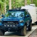
I have full XPEL PPF in stealth satin/gloss on my M3 with XPEL XR Plus tint 70/20. First place I took it after pick up was the detail shop. Also, have gloss bra coverage on the Tundra as well. Did you ever post about the PPF install on your Oliver? If you did, I must of missed it. It is great stuff, along with ceramic coatings, tint, etc. CGI is using another brand but still top tier PPF. Nice find on the 2020 Tundra PRO BTW, very popular move these days. -
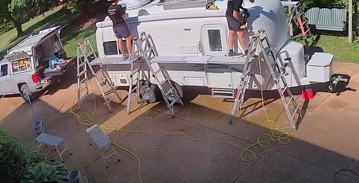
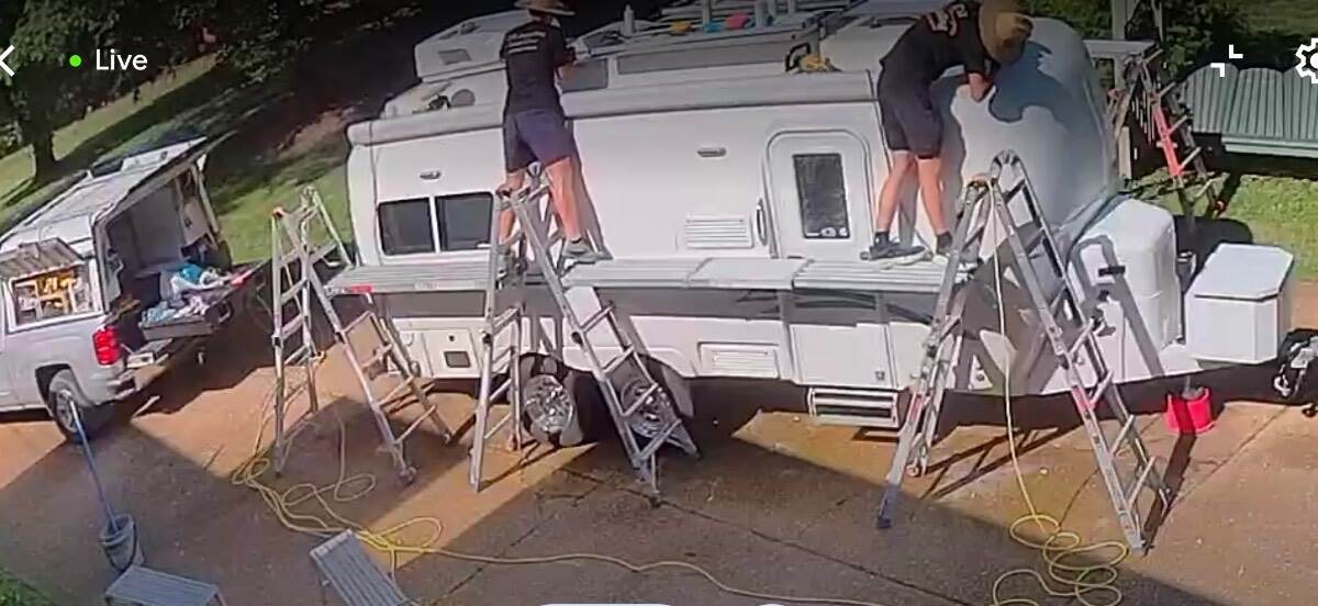
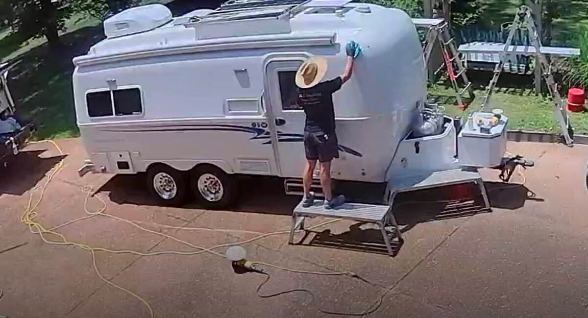
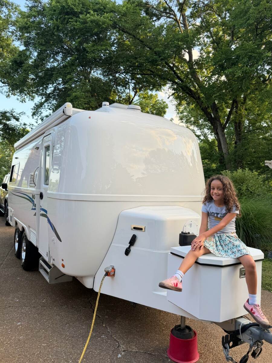
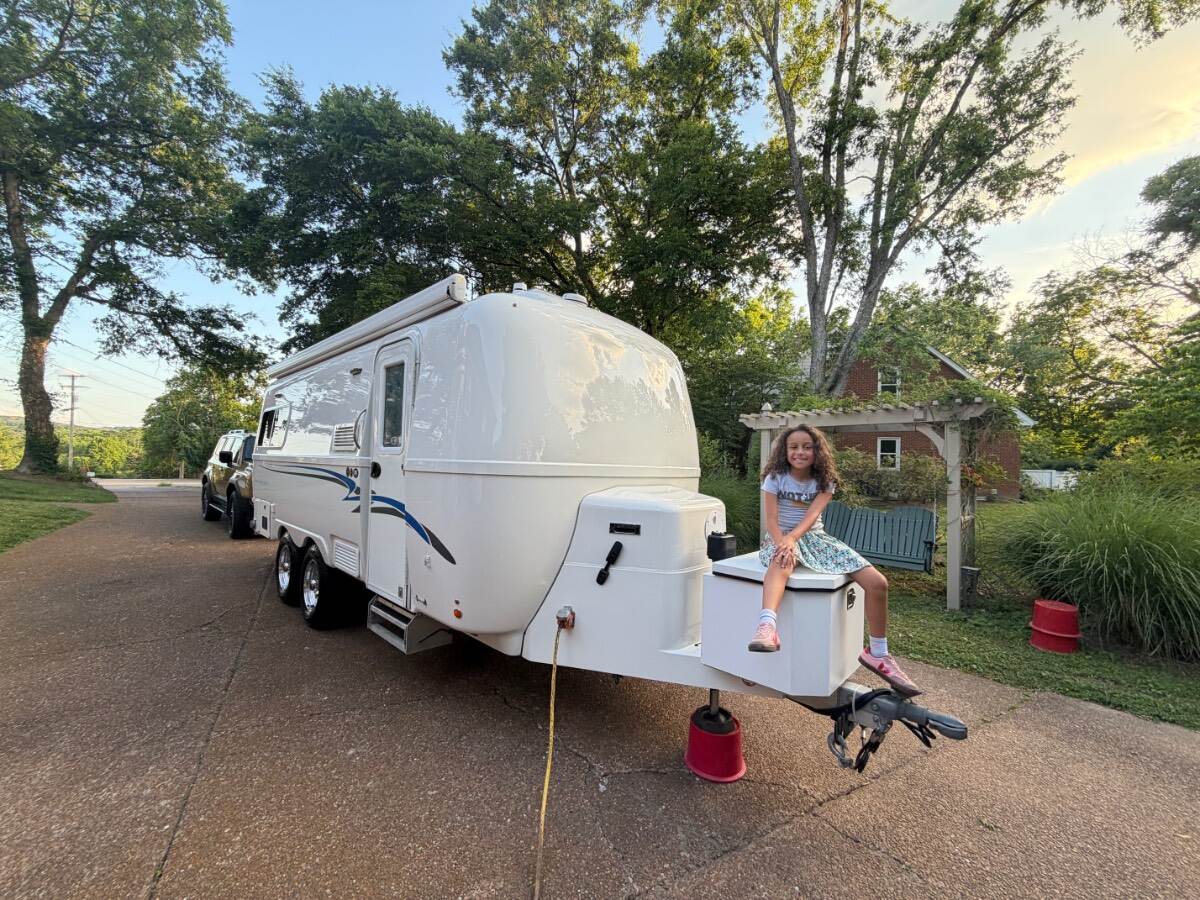
I Just recently had CGI do the annual touchup on my camper and they told me about a new service they are offering. It is a durable protective gloss film that they apply to the front of the camper. Might be a nice thing to have if you like getting off the beaten path (gravel roads, ALCAN Hwy, etc.), it would help protect the gelcoat from chips and make it easier to keep clean as well. Lasts 5-7 years or more typically and is generally easy to remove/replace. Not cheap but makes life easier and protects your investment. Short video link: IMG_8147.MOV
-
Collin and Gavin (CGI Murfreesboro, TN) did a superb job on my camper right before they left for Maine. I always tell them, “It looks better than new.” Worth every penny for the annual job. If I lived in Maine and owned an Oliver, I would definitely take advantage of their skill set while they are there.
-
If you are invested in the Milwaukee ecosystem, pretty handy tool for camping and more! Not as strong or pinpoint as canned air in some cases but handy nonetheless. https://www.milwaukeetool.com/products/details/m18-brushless-precision-blower/0887-20
-
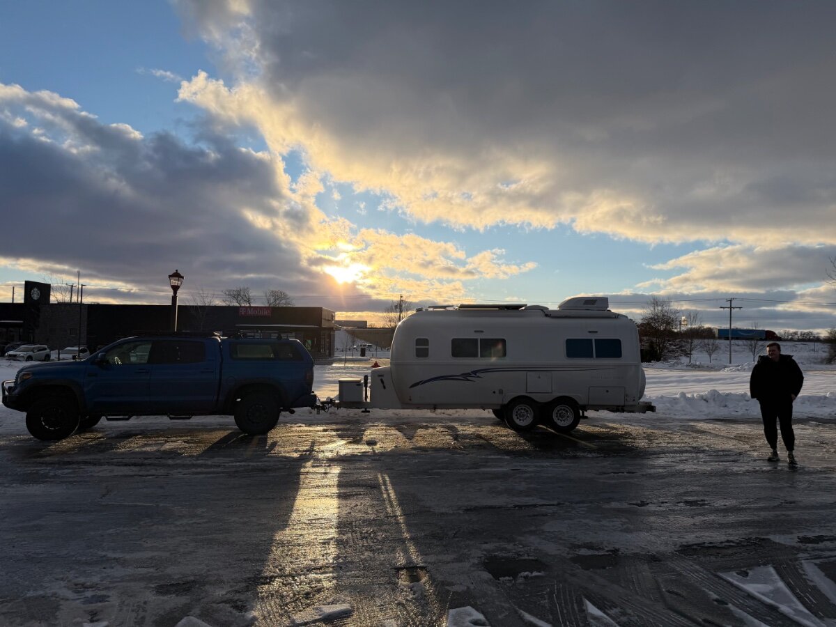
First, every tow vehicle and load is different and everyone should be conservative and safe. Personally, I have been towing an 2018 Oliver Elite II without a WD system from day one (February 2018) with an 2016 Tundra and it has performed flawlessly. I did upgrade the TV brakes and rear leaf springs when I lifted the vehicle for even better performance. Alcan leaf springs for the OEII. I post just to say every truck is different and I am sure every lawyer will look at it differently. I enjoy towing with my 2016 5.7L Tundra keeping it simple, robust and safe. My only snafu was the undersized OEM coupler breaking coming up I-75 (upgraded to 12k). Whatever you are using; check the hitch, coupler, tires, wheels, load, WDS, etc. every time you head out onto the road. If you notice porpoising or tail wagging, etc. something is wrong i.e. Overloaded in the rear, tire pressure issue. DO you have trouble getting the TV and TT to sit level? If your vehicle manufacturer calls for it or if you experience towing issues as previously mentioned, maybe you need a WDS or to redistribute the load or a sway bar or upgraded suspension components, brakes, etc. I love this forum and all the information and smarter, more experienced people than I, but I don’t think it is necessary to be told you cannot do something. Cheers to everyone out there and be safe. Hopefully this adds to and does not confuse the conversation. Best, M Key 2016 Tundra Towing Details: Max Tongue Weight (Weight Distribution): Typically 1,200 lbs. Max Tongue Weight (Dead Weight): Typically limited to 600 lbs. Max Towing Capacity: Up to ~10,000+ lbs (5.7L V8), depending on configuration. Class IV Hitch: The standard integrated hitch receiver on the Tundra is rated to handle the high capacity.
-
On Ollie Elite II. D35 bad. D52 good, with Alcan springs even better. 🙂
-
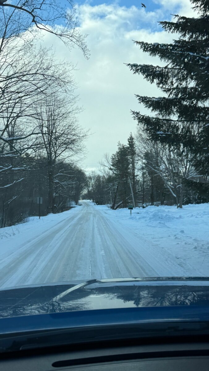
You camp and learn. We were at my dad’s in southern MI this past week with temps dropping down in the single digits. Atmos 4.4 heat pump quit working immediately and the plug in electric heater was taken out during the last cleaning and forgot to put it back. Propane tank gauges were showing zero and the Truma water heater started blinking yellow. After turning off the water heater and Atmos several times and verifying propane level by weight we turned on the Suburban propane and stayed warm and cozy for the next 2 days without further problems. It is a learning experience every time you forget something or encounter something challenging out in the wild blue yonder. Part of the adventure! Glad you were able to find some AC for heat, redundancy is key .
-
Trip to Michigan in subfreezing temps put the Atmos 4.4 heat pump to the test. 2nd night starting blowing cold air only and then shut off. After multiple restart attempts, turned it off and started up Suburban propane heater. Also, Truma water heater was not happy with the low propane pressure related to single digit temps. Not a win for cold weather camping. Waiting till we get back South and warmer weather to investigate the heat pump issue, etc. Thank goodness I decided to keep Suburban propane heater!
-
-
So about the same as a Dometic 13.5k AC on high powered by 12V DC.
-
Driving with AC on for a short period
rideadeuce replied to Wayne and Karen's topic in General Discussion
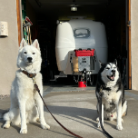
Very easily done. The Cielo Home app and others work great with the Atmos AC unit. Just have to have a compatible unit. You can monitor, change temp or mode, and turn on/off from the tow vehicle cab. I regularly make the journey from Nashville to the beach with the AC set to 72 degrees. Our two Welsh terriers have the best seat/bed for the drive down. We do have a 900 aH battery bank and usually have 20-40% left over sometimes more since the DC/DC charger and high output alternator install. -
rideadeuce changed their profile photo
-
Not sure how applicable smart glass would be for an Oliver trailer but the function is awesome. In the camper below, all the windows and bathroom glass are smart glass which can change from clear to opaque with a push of a button providing instant privacy. No tracks to clean or window treatments to manage. https://www.smartglasstech.us/city/usa-smart-glass-technologies-landing/ Changed the video to one without music. It shows the smart glass function but the longer videos show it’s use better. Also, linked made in USA manufacturer site that explains more about the technology. Best, M
-
Curious if you have the vent installed to allow air in when extending the hose with the terminal end closed. I would prefer not to use it if not really needed but my hope with the new system is to keep it always connected. Figured with the electronic black valve closed, I could always just crack the distal end open enough to extend, etc. What has your experience been.
-
The problem starts every time it starts back up! 😆 I know this is a very individualized thing but I actually like the unit and/or fan only running continuously, especially if it is quiet. It was the loud start and stops of the DP2 that woke me up during the night, etc. I am very hot natured and live in the humid SE. What Ron has figured out is better than the other options of timing out, manually shutting off the unit, or using the AUTO mode with no ability to refine temp settings. Hope everyone has a great weekend!
-
I didn’t think I needed this since already having the remote and other app control but I believe I am going to try it. Being able to more clearly refine the control is what we all want. Thx for sharing the product and evaluation. … now, where to place it? USB power makes things interesting.


.thumb.jpg.e34bf01ef7f7d5e99ad31856d45afbeb.jpg)