
jd1923
-
Posts
3,136 -
Joined
-
Last visited
-
Days Won
227
Everything posted by jd1923
-
So... Before leaving Brainerd MN and heading west, I thought to watch the movie Fargo! Streamed it on Amazon Prime and after half watching it, last time in the late 90s, we had no idea it took place mostly in Brainerd Minnesota! 🤣 Like the movie Fargo, the next few days would take some time, but I promise nobody we know ended up in the chipper-shredder!
-
It’s likely the age difference between our hulls. If you keep up with yours every year or two they may stay nice!
-

Navigation in 2025; smart phone via car play, traditional GPS or other
jd1923 replied to routlaw's topic in Towing an Oliver
Yeah, I would do that too! But not what OTT installed years ago. The screen is bulky and low res, and not sitting on my dash. Do I remember correctly, powered by a cigarette lighter plug? Mine has been in a box since we got our Oliver 2 years ago. Except for our Victron inverter and multiple charger systems, total rewire of all things electrical, a bunch of sensors and apps, powered water and waste valves and a few other items, like our Samsung A/V system… Our Dodge and Oliver are mainly old-school! 🤣 -
That's the real difference. We hope to travel so not to use the awning, nor the air conditioner for that matter! It's 52F cloudy with light rain here in Brainerd MN today. Yes, the awning could have helped for the rain, if I put it up when we got here yesterday. But, we were hearing thunder and you can't trust to leave it out overnight in these conditions. Get stuck in a burst of wind and downpour trying to manually retract it. I imagine that wouldn't be fun, so ours just doesn't get used.
-
Us too, we never use our manual awning. Tried it once to know how to extend it, and since it was such a pain to do so, I haven't wanted to open it again. If we had the powered model, I would have used it on this rainy morning for a little protection at the doorway when we took our dog out for morning business. Also if we had the powered model, in a heartbeat I would rewire it to bypass the auto-retract feature. I dislike features that idiot-proof for idiots! People should realize when it's windy and know to retract a power awning when leaving the campsite. 🤣 Last time this subject came up, I offered all who complained of their powered models to trade for our dependable manual awning in like new condition. We got no takers.
-
We moved out of the Midwest 26 years ago and there were two things I had forgotten about, one bad and one good. The bad are the huge storm fronts that can come through slowly and sometimes just sit for what seems to be FOREVER! Low pressure started with the storm that came through central Kansas. Then we caught up to it again the next day in Nebraska. And then it was still there ALL through Iowa and after two rainy days at Wilkinson Pioneer Park near Mason City Iowa it also covered most of Minnesota (so far). Fortunately we only had 3 rainy days but we have not seen the sun in 12 days! Let me tell you, this is difficult for us who live in sunny Arizona. Non-descript GRAY skies. You can't make out clouds, it's just a pale shade of gray. I remember a year in Chicago about 1980 when the Chicago tribune headline stated 45 days of gray. That was during the winter though, the first 12 days of June being nothing but gray, wow! The good one I had forgotten was how large and tall deciduous trees can be in the Midwest. Over the last 20 years we've lived in AZ, Central TX and S FL. No tall trees in these locations except for Ponderosa pines in AZ. Every town in Iowa, the pretty houses are surrounded by huge tall trees. Then we got to Chris' sister's home in Farmington MN. This was our best campsite so far. A private little spot in the woods along their driveway a couple hundred yards before their lakefront home. We spent 4 overnights with family here. We left today and drove up to Brainerd MN, staying Gull Lake Rec Area another ACOE park. Drizzle and gray again today. Just staying here one night. The plan is to boondock in the Chippewa NF for the weekend, but... If it's raining to the north when we wake up, I'm driving west to Fargo ND or further west as far as we must to see the sun again! 🤣

-
Can I tow an Oliver LE2 with a 2006 SR5 Tundra Double Cab?
jd1923 replied to Dirt Duff's topic in Towing an Oliver
Most of us suggested no but you can just make it, if that's what you want. However, the mountains of the Pacific NW is not an easy traverse. I have an older Ram Diesel and wish it had more than a 4-speed trans and an exhaust brake like modern diesel trucks have today. The mountains we travel through are not an easy climb for the trans and not as easy descend on the brakes. I also upgraded wheels an inch larger to upgrade to larger brakes of the next gen Ram, big help. I believe the 600 LB number is subtracting the average weight of a full 5 passenger load from the total available 1421 LBS. Another thing from your tire pressure label. Same on our GX, Toyota puts P-rated tires on these trucks, P stands for passenger cars. It's a must with towing to upgrade to LT tires. Our GX now has LT265/70R17 Load Range C tires and if I was going to tow with it regularly I would have purchased Load Range E instead. -
Can I tow an Oliver LE2 with a 2006 SR5 Tundra Double Cab?
jd1923 replied to Dirt Duff's topic in Towing an Oliver
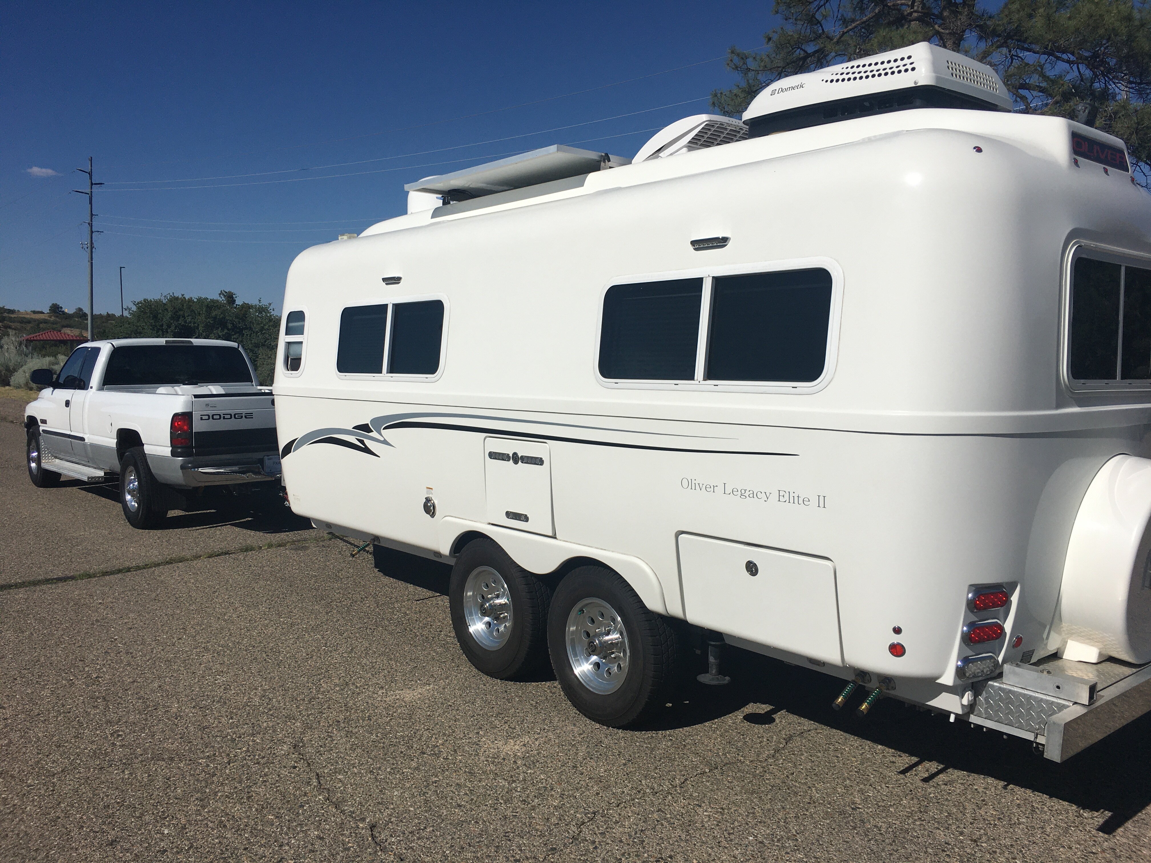
Simple answer, NO. When we purchased our Oliver EII two years ago, I was hoping to pull it with our ‘08 Lexus GX470. So, same engine with some frame differences and ours has completely rebuilt Eibach suspension, new springs shocks, CV axles, everything. I installed a Redarc brake controller and this GX has the tow package. I pulled the Oliver around town. The Oliver was tossing the rear of the GX left and right, up and down, btw with the Andersen WDH attached. Came home and I looked at Chris, “Honey, we need to buy a truck.” She nodded, yes in agreement. Several owners do this, that or the other to make their half-ton truck or even an SUV work. Do yourself a favor and get a 3/4 ton truck with long bed so you can carry what you need now and through the years. Our Oliver was 6400 LBS first camp out, thinking we must be a couple hundred more today. Our truck has 8,800 LB GVWR. BTW, when I did my test drive, third row seats in the GX were removed, rear cargo area empty. The Oliver was also pretty much empty, fridge closet cabinets pantry, were all empty. It’s better to feel you have AMPLE capacity, not close to advertised limits. Sorry. -
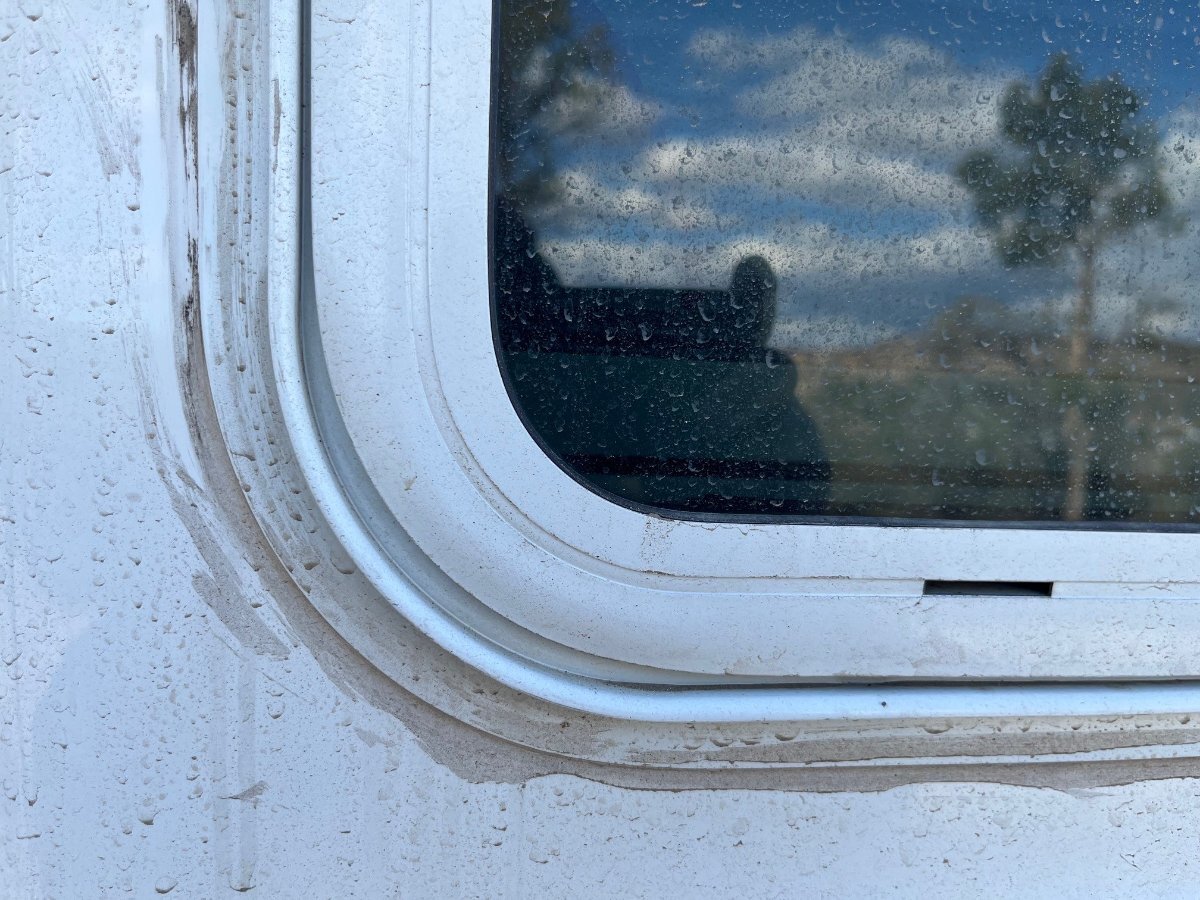
Having done our last year, I do not believe the freezer would help. It will make them stiff and hard to manage. The second part of this sentence is certainly true. I started at the bottom pushing and pushing to compact the rubber. In the end, I cut it to what looked like almost an inch long and pushed it all in the channel. We all have or had the 1” gap from a lazy original installation. Buy the black stock. I soaked our original white ones in bleach overnight and it did not remove any of the mildew. I did not try a mildew remover as suggested above. I wanted new black stock and for under $100 they look great and should stay nice since they’re not white!
-
From the outside these windows look sleek! Inside view, not so much. That’s a lot of black frame for our white interiors.
-
Thanks for this Patriot. I've been wanting to add front and rear porch lights. I'll buy two of these for this purpose. A front porch light for unhitching if we get somewhere late or need something out of the back of the truck at night. I'll want switch outside next to the jack switches and will have to figure out how to get wiring between the hulls to the new light. The switch below the doghouse will be easy. I want a rear porch light too since there is no light pointing that direction. I'll likely use the "Rear Camera" switch for that since we don't use the camera and it seems odd to have a switch for that purpose anyway. The rear will be an easy installation since there is already switched power for the rear camera to use. With these lights, mounting two new lights at the same height (measure up from hull seam), we'd have 6 lights separately switch in the 4 directions and the install would look OEM. I agree with your idea of lighting up the place with individually switched porch lights for safety needs. We don't use the porch lights unless we want the light to extend outwards. Happy our hull has separate Entry and Porch light switches. Our older hull also has the older dim Courtesy lights which I noted at the Texas Rally, our neighbors Courtesy lights were easily twice as bright. If not, I would do what @Ollie-Haus has done with Z-brackets. Beautiful work, smoothly cut with radius corners, nicely painted, excellent! 😂
-
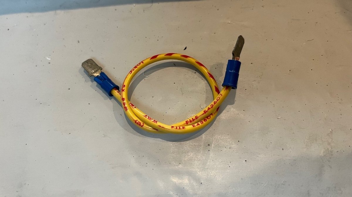
Yes, there was just a thread on the wiring of the jack switch (link below). And these switches go bad regularly. What you described is very likely a switch that needs replacing. Also, everybody should carry a simple spade jumper like pictured below. The Oliver has many toggle switches installed and this simple jumper can be used as a temporary override. I had a brake pedal switch go bad on a Class-C which would not allow me to move the auto trans gear selector out of park. We were stuck right were we had parked. I used a jumper like this to bypass the switch which allowed us to drive an hour or two into the next town to get this common replacement switch at Napa. They also would likely have a replacement toggle switch for the jack. Nice little tool to have handy. I made one when we had the brake switch failure and have carried it with ever since. Used it once when the Oliver had a bad water pump switch under the pantry which allowed the switch under the bath vanity to work.
-
Victron Multiplus II 3000 - Installation Xantrax Removal
jd1923 replied to Ty J's topic in Ollie Modifications
Test it on a 15A household circuit. -
Happy 50th to Oliver friends John & Susan! 😂
-
Well we just hit 26 pages. I remember asking the Mods to close this thread after 12 pages, but it was not my thread to close. Most of the additions I've read here in the last 10-15 pages are slight variations of the comments and questions made in the many pages before. I just reviewed pages 1-2. And yep, that's all you need to know on this subject. Except that a few pages later we learned that the Alcan springs are actually rated at 2750 vs. 2000 lbs. There was the same concern on page 2 about this rating being too much. I had that concern early but no anymore. We're on a long road trip where we have not before towed so many highway miles. Our OEM springs are in very good condition, no sag, still nicely arced and perhaps Dexter used better steel in 2015 than more recently. Who knows but htey're in excellent shape and no rust given where we live. When the other day, I crossed railroad tracks that were on about a 30 degree angle to the road, I watched our Oliver in the side view mirror. The Oliver waddled like a duck going over those tracks, side-to-side, the top of the Oliver swayed a good 1 1/2 ft like a pendulum both ways! These springs are under-rated, as the Alcan rep stated. It's crazy that this is our 2nd longest thread, just behind "Where's Ollie" at 28 pages! This truly means not enough of you are posting travel pics! 🤣
-
As Bill @topgun2 mentioned, “right where you connect your hose into the boondocking port” the rear hose bib itself. If it wobbles, it needs tightening. There is a hex opening inside, maybe a 1/2” (13mm) hex? Not certain of size. When we bought our Oliver used 3 of 4 were loose, and since I have the correct Allen key in our tool bag for when needed again.
-
So our 31st anniversary was spent a few nights ago. Nice to spend it in the Oliver! Today is Chris' birthday and our 2nd year Oliver Anniversary to the day! 'Twas 2 years ago today when I surprised Chris with the Oliver in our driveway! See the first picture of this thread for our Day 1 picture. Two years going strong and so far 92 overnights in our Oliver (will hit 100 soon on this trip)! We are camping near Mason City, north central Iowa. Was hoping for some pickleball today then dinner out. Pickleball will likely have to wait unless it clears out this afternoon, but we'll have a nice dinner out either way. Thinking of the Blue Heron Bar & Grill. Hard to imagine a place that has 5-Stars on Yelp with 89 reviews. Wow, it should be good! One more night here and tomorrow we will be with Chris' sister in Farmington MN, just a 2-hour drive from here. Charley's birthday is next week too, when he will turn 11. He sleeps a lot, is a bit hard of hearing, but still our great family dog! Isn't he pretty? Proudly protecting his Oliver!
-
Spent the night NE of Omaha, just into Iowa at Arrowhead Park. It was an OK overnight, very nice host. He kept things very clean and neat but somehow too many flies everywhere. Thankfully they stayed out of the Oliver somehow. So as we're driving down the road, Chris is on her phone searching for local farms stores, for farm fresh eggs and meats. After a 5-mile dirt road detour we found Wild Rose Pastures in Madison County IA. A knock on the door and only a 12-year-old boy was home. Chris talked him into calling his Dad, saying tell him I'm a "safe old lady." After Dad talked him through the transaction, we left with 2 dozen farm fresh eggs at $5 per. There were big beautiful healthy hens running all over the place, a little nervous that we were there, ducking in and out of the barn! We also purchased 2 small T-bone steaks for only $15, a herd of cows beyond the farmhouse. I tipped the young man Zane $5 for his help in the transaction. You can eat well in Iowa on a budget!
-
So we headed north out of Kansas. NE Kansas has some great countryside. We drove through the cute town of Marysville, cobblestone or brick streets throughout the downtown area and it appears they area is known for black squirrels. They must have 100 of these squirrel statues, on every block! We got to Lincoln Nebraska by late morning and played pickleball at Peterson Park. There were 10 courts and a lot of local players. None at our level though, so Chris and I played Skinny Singles. as the locals were thinking, who is this old couple! We started playing tennis together 34 years ago and are usually pretty even in competition. It was Chris' day (and her birthday week) so she won 2 of 3 very close games.
-
My how-to video for cleaning the weep holes and tracks
jd1923 replied to Wayfinder's topic in Mechanical & Technical Tips
Amazing product to remove these mildew stains! Yes, water pressure is all you need to clean the internal dirt out of the weep holes. Still happy with the $100 upgrade to switch to black rubber and have them fit tightly end to end without the 1” gap we had on each piece with the OEM installation. -
Victron Multiplus II 3000 - Installation Xantrax Removal
jd1923 replied to Ty J's topic in Ollie Modifications
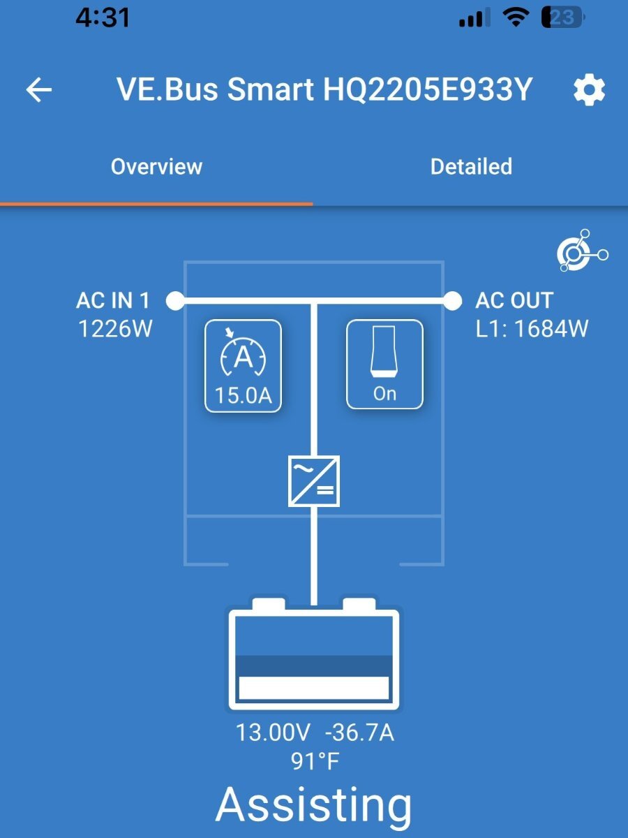
I thought to find an old thread I had remembered reading, just after I had joined the OTT Forum. At first, I did not understand the value of this feature. How would Victron Power Assist be of value in a real-world use case? Thank you @Ty J and others who had contributed here (now over 2 years ago). We love our Victron Multiplus II, OMG! Camping in south central Kansas, a muggy day that was going get hot, mid-to-high 80s over the afternoon, and we wanted to go for the day... Leaving our older pup Charley to rest in the Oliver while we were gone. The Dometic with SoftStart would not run on this public "20A circuit" alone, without blowing the breaker. I set the MP2 limit setting for incoming amps to 15A to be very safe 75% of the 20A commercial circuit (to lower the probability of blowing the breaker). We ran the Dometic Pengiun 2 A/C, set to 69F. The 600 Ah batteries were high 90s SOC due to our Orion DC-DC charger running as we drove in the day before. The Victron app showed -40A on startup, so I was thinking we would lose 30-40% SOC while gone for 4-5 hours. We were gone a full 5 hours. The SOC on 600 Ah, in Power Assist mode, dropped only 20% (compressor only running 60% of total time). All was good, A/C running, the Oliver interior nicely cooled down and all systems running as programmed. These are the results. Notice AC OUT at 1684W - 1226W AC IN = 458W supplied by batteries (at 96% efficiency: 458W / 13V x 36.7A). I've never before seen this screen on the Victron Connect app for the MP2. There truly is a working Power Assist mode, not only in how the MP2 Inverter/Charger functions, but as a listed display mode as shown. This feature works well and as advertised. 😂
-
I hate that! I still have it on my list to remove all the old caulk on our 10-year-old hull. Our hull went for OTT service in 2018 and 2020 according to receipts I have. They must have done all the messy caulk on top of caulk work, yes sloppy to say the least. What a shame on your only 1-year-old hull! There is no reason in the world they should have gone over yours. Caulk should last YEARS and caulk over caulk is never a good idea! Here is an example of the handywork of such an over-zealous artist! 😞 Picture is after travel on a dirt road which makes it show fully --
-
After 25 pages of comments, it's been jacked a few times. All anybody needs regarding the Alcan Leaf Spring mod is the read the first couple of pages. 🤣
-
I didn't like the TV mount OTT installed or the newer versions. I do not trust the latch mechanism and the TV should fold back, so when viewing it is near the back window vs. on the front side of the night stand.
-
It appears Mike may have one for you. I have the whole setup, not using it, but will not be back home 'til July.