Galway Girl
-
Posts
790 -
Joined
-
Last visited
-
Days Won
25
Everything posted by Galway Girl
-

Going West! Random Thoughts on the Road
Galway Girl replied to Boudicca908's topic in General Discussion
Sorry we’re not home in Everett to meet you. If the clinton to Mukilteo ferry is in your plans, consider lunch at Ivars in the Mukilteo waterfront. When exiting the ferry take a right into the hwy, then a quick left at the next light into the waterfront park parking. You could have lunch at ivars ir visit the scuttle but brew pub. We are in Hells Gate State park today.
-
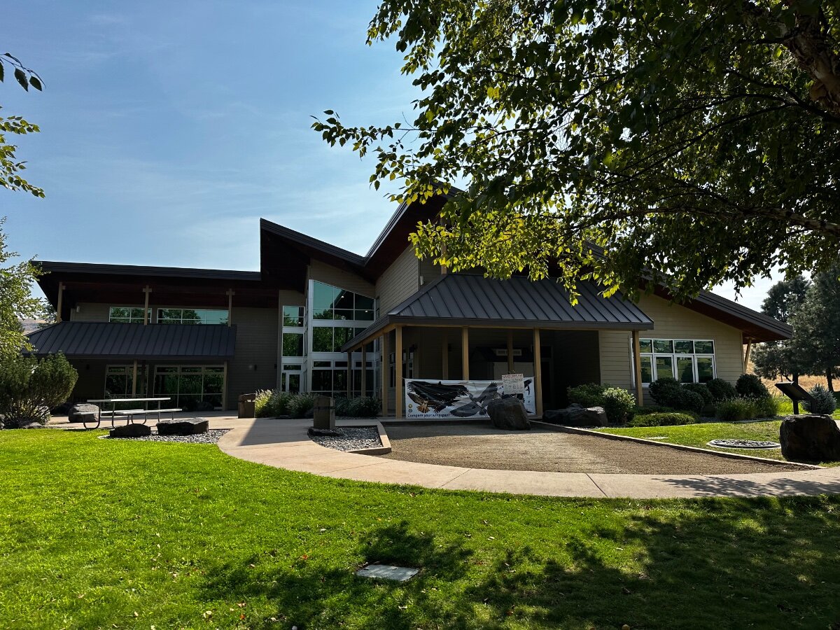
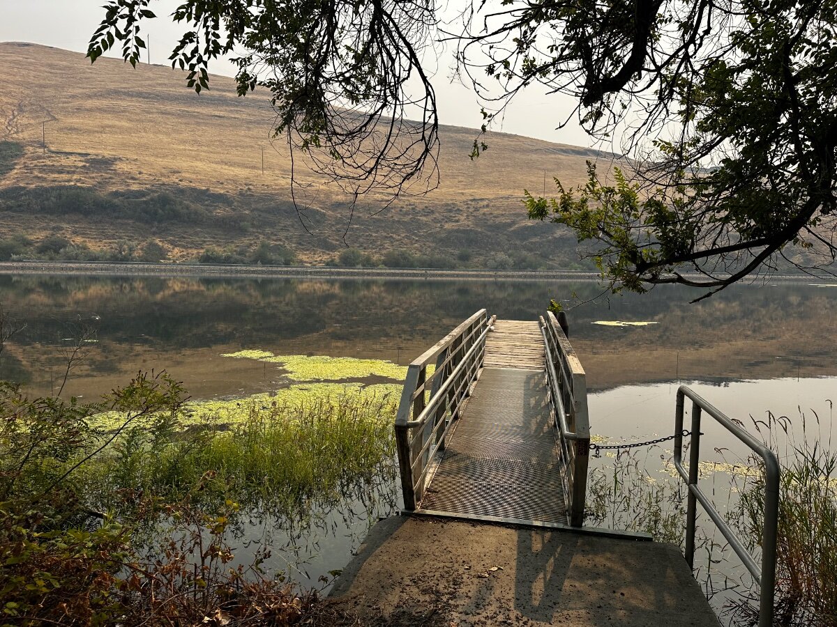
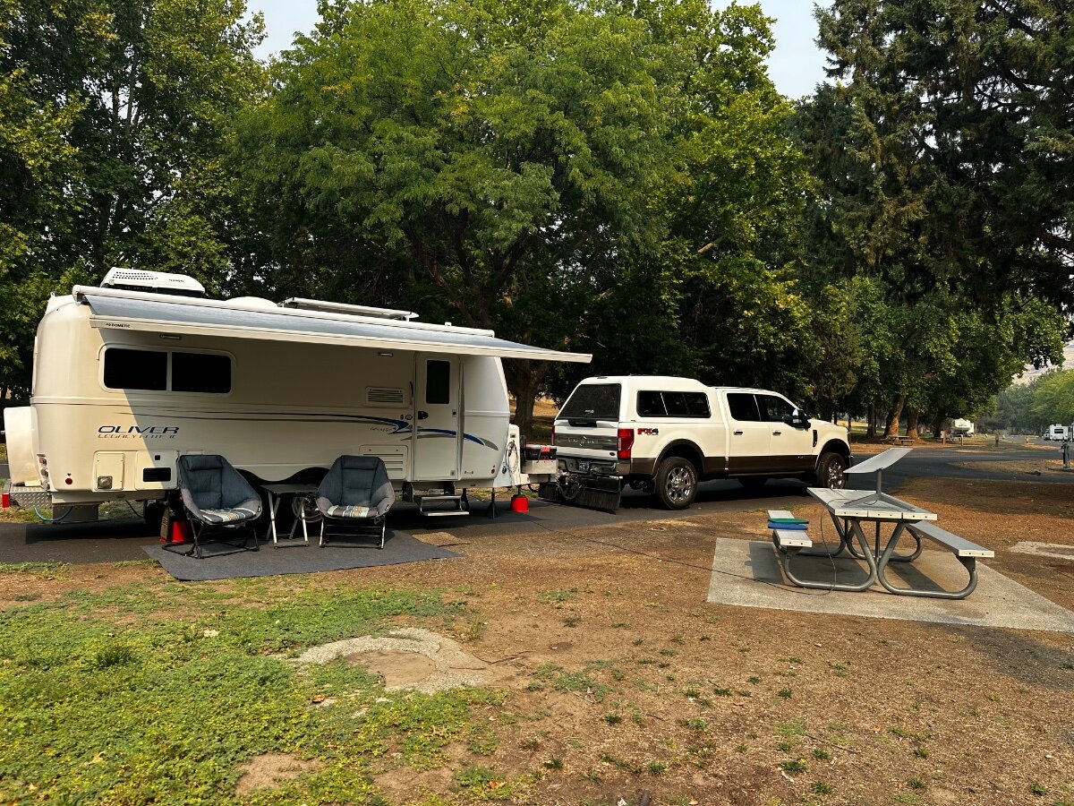
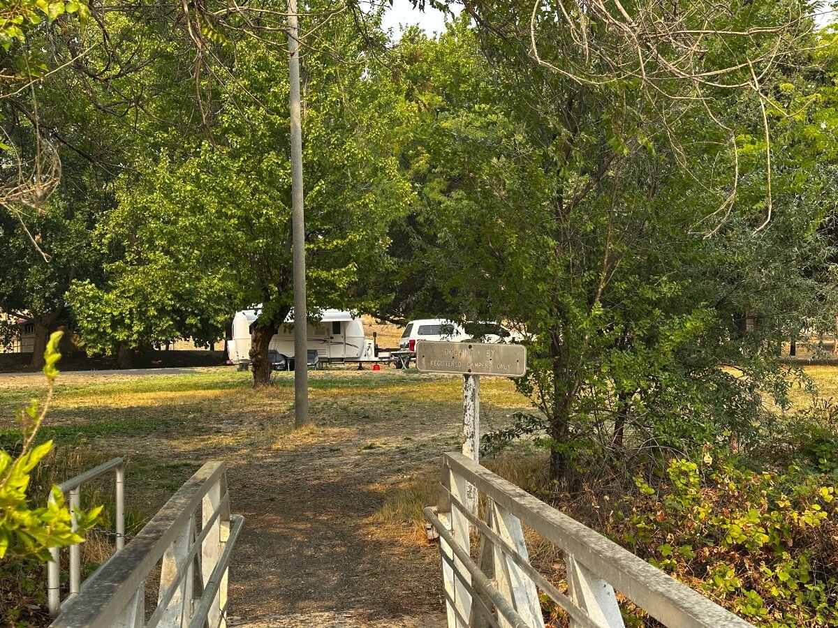
At Chief Timothy Park site 7 near Clarkston Wa A 1980’s COE park on an island in the snake river (connected by causeway) now managed offline by Vista Outdoors under a lease next stop Hells Gate SP on the snake river About a month out from Alcan Springs appointment!
-
2026 YM Oliver awning style windows and other changes
Galway Girl replied to Patriot's topic in Ollie Modifications
Guess we all have different cooking styles. We’ve had outdoor grills, and camp stoves and recently started using an induction plate outside and the magma pans and some cast iron are a go to for cooking outdoors. -
2026 YM Oliver awning style windows and other changes
Galway Girl replied to Patriot's topic in Ollie Modifications
The best induction cookware we’ve owned is a nesting Magma set! MAGMA Products, A10-362-IND 7 Piece Induction Cook-Top Gourmet Nesting Stainless Steel Cookware Set: https://amzn.to/3vmDVEo -
Starting 6 month road trip at Maryhill SP WA on Columbia River today.
102F when we arrived at 4:45pm but river was dead calm.

-
Truck Charging Wire location inside OTT
Galway Girl replied to dewdev's topic in Ollie Modifications
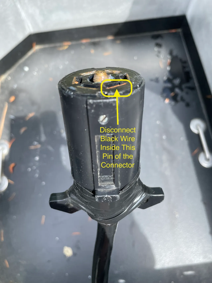
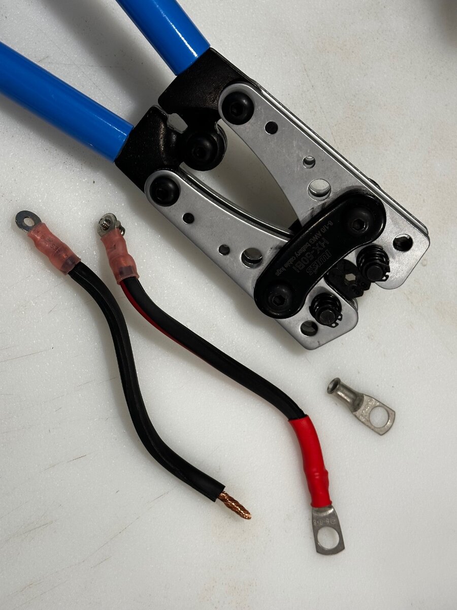
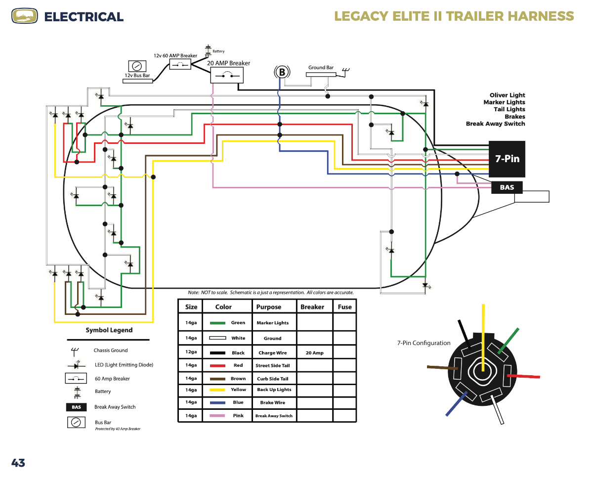
See section 7 of the article on the upgrade ...in our 2019 EII manual it shows it as a Black Charge wire as shown in the wiring diagram and in the PICTURE below. The reason we disconnected the wire inside the 7 pin cable was to protect the alternator. Lithium Batteries they can "draw" charge current much faster than older AGM or other Lead Acid Batteries...so ultimately they would try to draw way more power than the truck wiring would provide. (To install the DC/DC converter you'll run dedicated lines back to the DC/DC charger.) Full battery upgrade is here...including the section 7 about disabling the charge wire. https://4-ever-hitched.com/blog-articles/f/lithium-battery-upgrade Step 7; Disable the 7 Pin Charge Line: We will be installing a new DC/DC charger into our Oliver EII. But before we do that install we need to disable the current charging wire that runs from the 7 pin cable on the tongue of the Oliver. That 7 pin connector is the one that plugs into the back of the truck for lights, brake lights, emergency brake power. Inside the 7 pin cable there is a BLACK wire that provides 12V (B+ ) from the truck battery/alternator B+ all the way back through the trailer, through a 20A breaker and back to the batteries via the 12V Bus bar in the trailer. We will not be using that (Black) charge line for the trailer an longer. We disabled that line on the 7 pin connector by putting heat shrink coating over the screw terminal on the black B+ wire conductor and also taping up the screw lead the body. We reassembled the conductor and tested that no 12V was present on the wires inside the trailer. Wiring Digram for Oliver EII 7 Pin To disable the Charge Wire (BLACK) from the 7 pin, remove the cover and disconnect the wire from the connector by taping up the wire and putting it back inside the cover. Don't cut the wire in case you need to use it in the future.
-
Ours broke after a rough dirt road in the Yukon. We happened to carry new brass shark bite fittings for that location. Trimmed it up and we're all fixed up in 15 minutes. I now carry an assortment of fittings and some short lengths of pex in the trailer.
-
Thanks for the reply. It's very helpful to have site reviews that state the campground and site for future reference. Sometimes we have had to do reviews and say our trailer won't fit or the sites very steep etc. Here's a steep side slope at Devils Lake State Park in Wisconsin. It was once a golf course turned into a campground and many of the side lots had large left/righ slopes.
-
What site number was that and which loop? Really great site!
-
So did you find the red one up under the dinette was for the composting toilet and red one in rear wheel well for zamp?
-
I have a 2019 and don’t have a fuse for zamp there. Our zamp fuse holder looks like that but is located in street side rear area by the rear wheel well. Our zamp connecter is on the side of the trailer just past the battery box. Maybe your zamp connector is near that fuse. Do you have a composting toilet? Did you follow the wires & look where the wires connect?
-
Battery and Solar Disconnect Install Questions
Galway Girl replied to Tony and Rhonda's topic in Ollie Modifications
Our installed wires from solar were 6awg zip line. The original terminals were 6awg so I left them in place. -
To add to this topic, In 2019 Models Oliver didn't install a solar cutoff switch. I've posted a how to add a solar cutoff in this blog post. link below: https://4-ever-hitched.com/blog-articles/f/install-a-solar-cutoff-switch#ba015e70-35c6-4ccf-a9f3-b05f12d7eb30 Craig - Hull 505 - Galway Girl
-
Battery and Solar Disconnect Install Questions
Galway Girl replied to Tony and Rhonda's topic in Ollie Modifications
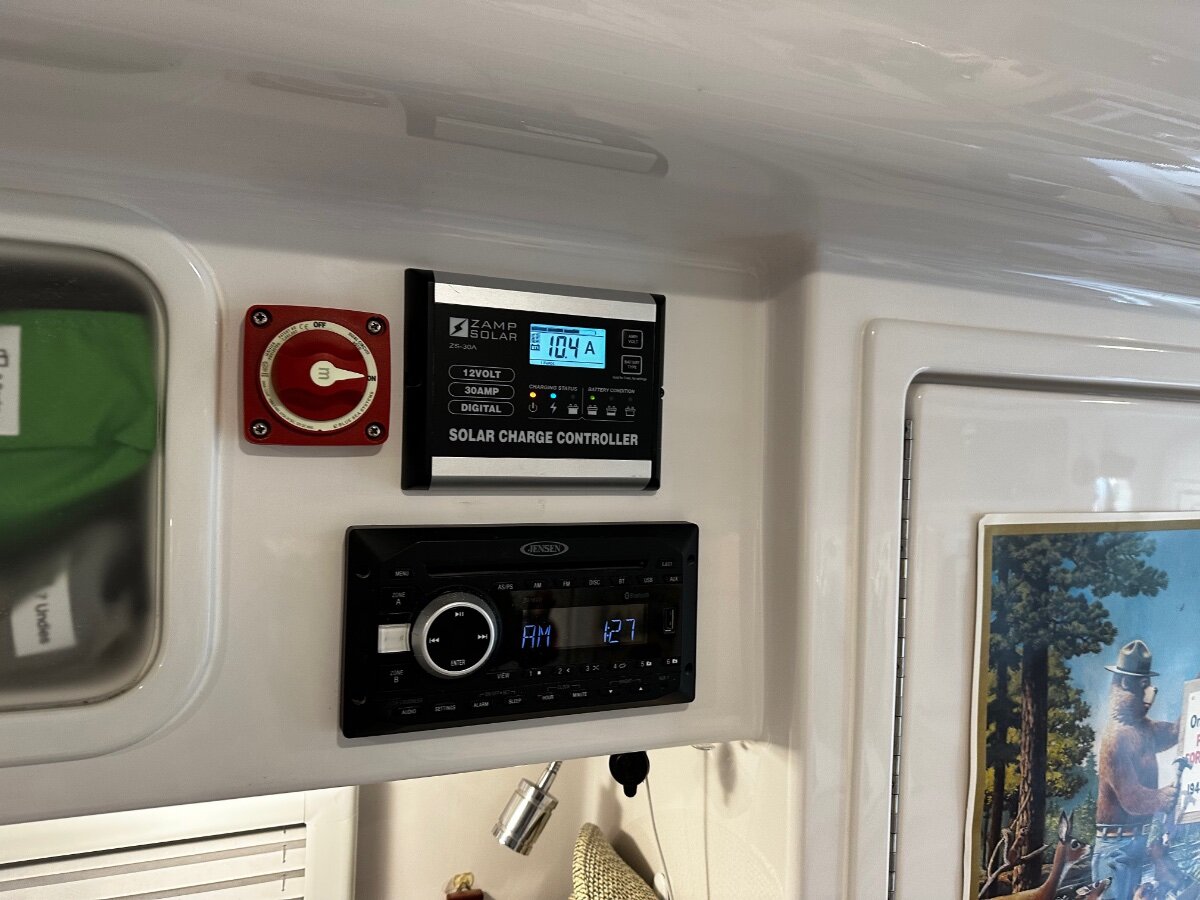
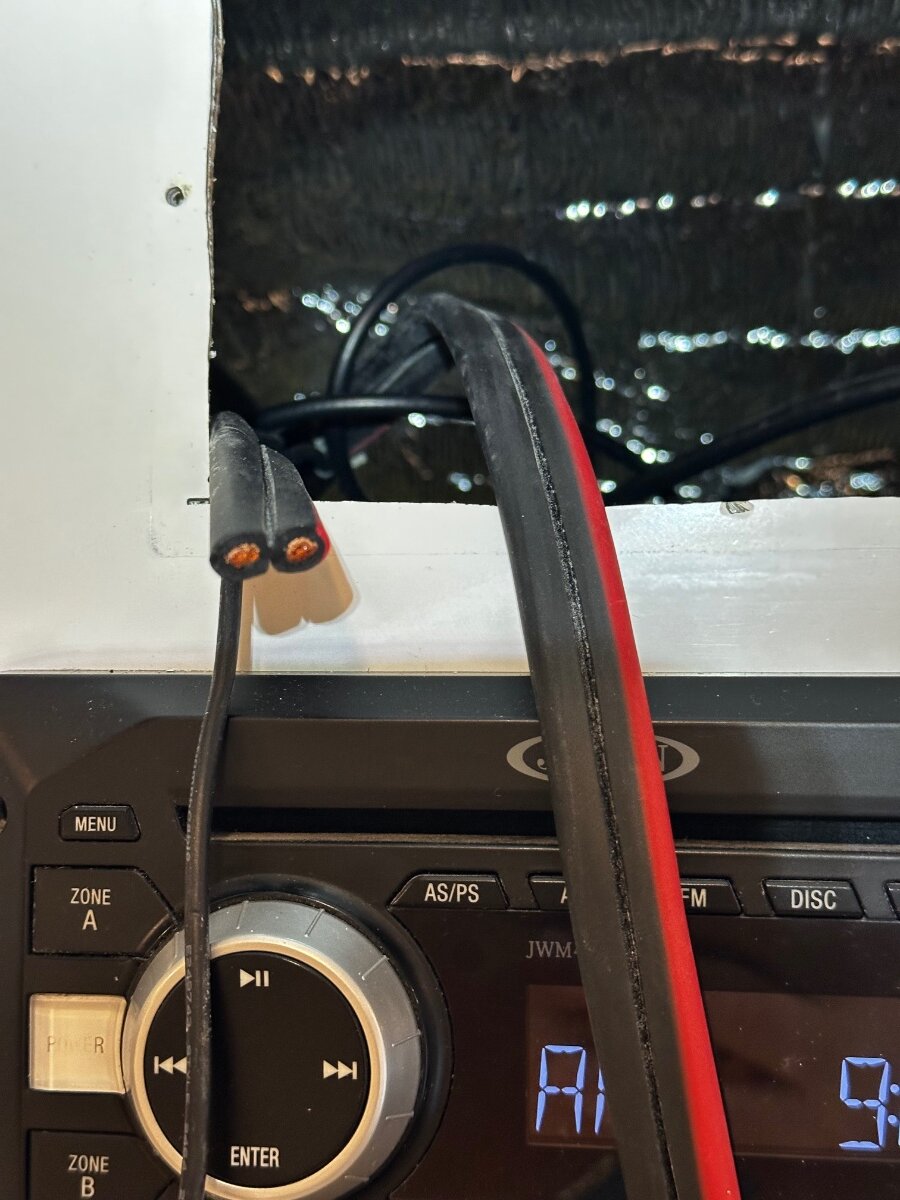
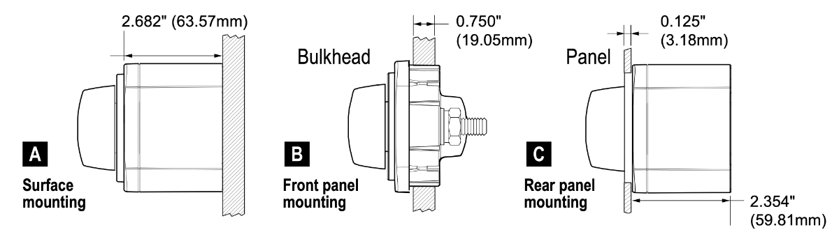
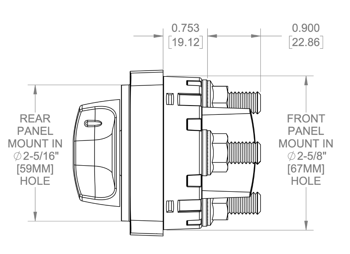
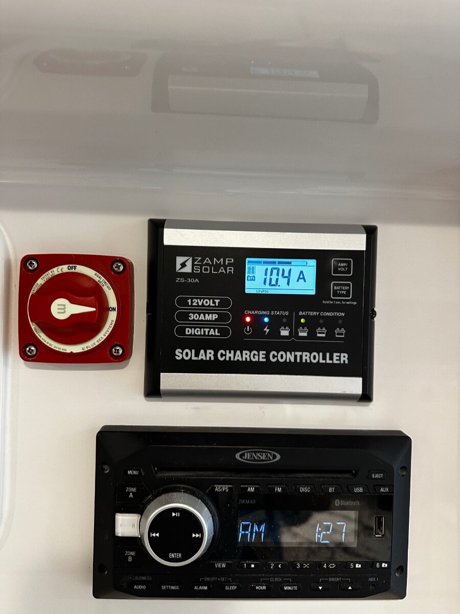
I like where you put your unit in the side of the pantry. I assume you had enough original lead wire coming from the solar panel to reach over to that wall. In hull 505 they left a ton of wire for the run after the controller down to the battery, but not an extra inch on the roof solar leads. I also just finished the installation of a Blue Sea Dual Circuit Cutoff Switch m 6010 and then read your post. Thanks for showing the pix ! Full Blog Post here: https://4-ever-hitched.com/blog-articles/f/install-a-solar-cutoff-switch?blogcategory=Electrical+Upgrades After inpecting the space I decided to mount the switch to the left side of the Zamp solar controller. A bit ugly but very visible to anyone using the trailer. I'll be adding a label just above the switch for instructions. Finished Installation Below - M 6010 Blue Seas Dual Circuit Cutoff Switch mounted as a bulkhead mounting. Here are a few "in the process" photos and the steps taken for this installation: SWITCH USED: Blue Sea Dual Circuit Cutoff Switch m 6010 WHY: The code for Solar Cutoff is that the switch must disconnect both legs of the solar panel leads. This means a dual pole (dual circuit) switch is recommended. Buy it from Amazon: Blue Sea 6010 Dual Feed Switch Mounting considerations: This switch can be mounted in 3 ways... I chose the middle - bulkhead front panel mount - for ease of installation. 6010 Blue Sea Switch Dimensions - Front Panel Mount hole saw size is 2 5/8". Installation Process: 1) Covered the solar panels with cardboard so the panels were dark with no voltage output. 2) Unplugged trailer from Shore Power and turned off the Lithionics Batteries. 3) Removed the 2 screws holding the Zamp Controller and inspected the space for positioning of the switch. 4) Decided based on my particular situation to cut off 5" of the leads coming FROM the Solar Panels. I reuse the cut portion leaving on the Zamp connectors to connect between the switch and the input side of the controller. (Note: If you have a bit more length on the input solar cable, it would be better to have about 8" of cutoff to make mounting the switch easier.) Here are the leads being prepped that will go from the output side of the switch to the input portion of the Zamp controller. The switch has 3/8" (M10) lugs, so I crimped #6 x 3/8" lugs to each of the cut wires. Heat shrink was added to each. (Note - I left the Zamp output leads mounted to the controller as they were and just checked for tightness when re-installing Zamp into mounting hole.) 5) Mounted the leads back onto the controller. Crimped the leads onto the lines coming from the solar panels. Next phase is drilling hole and mounting the switch. 6) Prepared and drilled the hole at the centerline of the controller and centered on the empty space. As I was doing a front mount of the switch I needed to use a 2 5/8" hole saw to match the engineering drawings for the switch. The bag at the bottom is to catch the shavings that come out the front as the hole is drilled. 7) Attached the input leads and output leads to the switch and tightened using a 14mm Deep Socket. 8. Mounted the switch by predrilling holes and then attached with stainless pan head #10 screws / 3/4". (Note - I drilled the holes slightly smaller than the screw so they had bite. You can also just drill holes and use stainless bolts with lock washers on the back side.) 9) Go remove the covers from the solar panels and test....voila you now have a solar cutoff switch for storage and safety while working on your electrical systems. Craig Hull 505 - Galway Girl
-
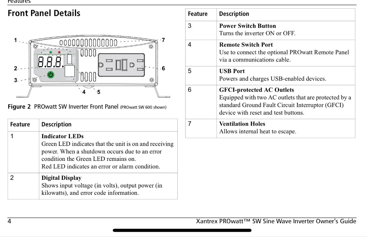
"The batteries are fully charged and my 110 outlets will not work with the solar. I am wondering if there is a fuse somewhere else in the trailer, other than the fuse/breaker panel or if I have a problem with the transfer switch, maybe? I'm asuming the problem is inverter-related, but not sure. I have the 320 solar watt package, with the Xantrex 2000 watt inverter. The batteries are fully charged and my 110 outlets will not work with the solar." is this statement true...batteries at 100%, you are not connected to shore power and your 110 outlets don't work....but your inverter is ON? Here's a checklist to help: Battery Charged (YES) Connected to shore power (Yes) (No) Inverter On (Yes) (No) Fridge Breaker Tripped (Yes) (No) = ours has a 20amp breaker in the panel for the fridge Inverter Built In GFCI Tripped (Yes) (No) = There is a plug in on the actual inverter that has a GFCI on it...see below GFCI In Outlet Tripped (Yes) (No) = Our hull has a second gfci outlet on the front of the dinette seat.
-
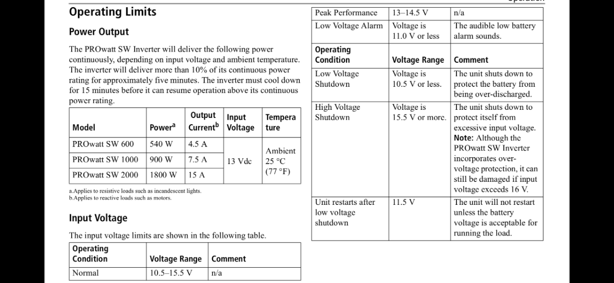
If your batteries are too low of voltage < 10.5v the 2000 watt inverter shuts down. the inverter should alarm on low voltage or give an E01 code. when you are in solar if the batteries drop too low the inverter will not turn on again until the batteries are charged When we boondock we leave the inverter off unless we need 110 as it draws down the batteries just being turned on. if you fully charge your batteries the inverter should begin working.
-
NO BRAKES ; 2019 Oliver Elite II-Hull #448
Galway Girl replied to BoondockingAirstream's topic in Mechanical & Technical Tips
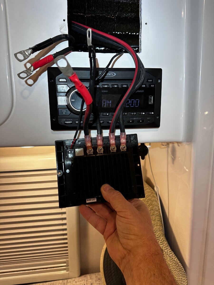
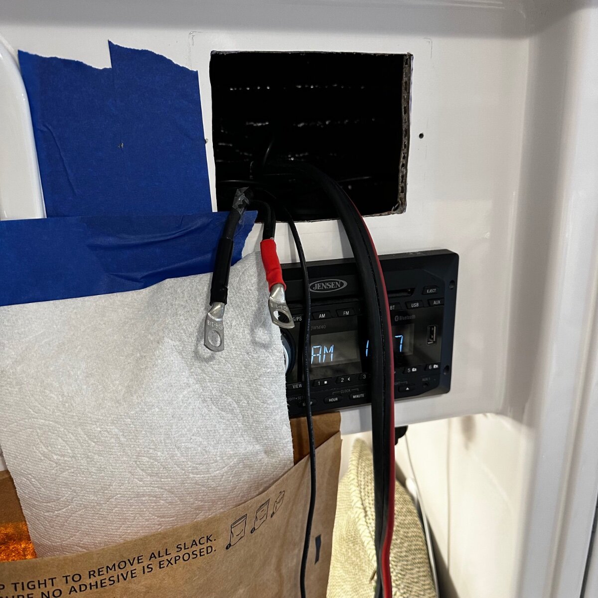
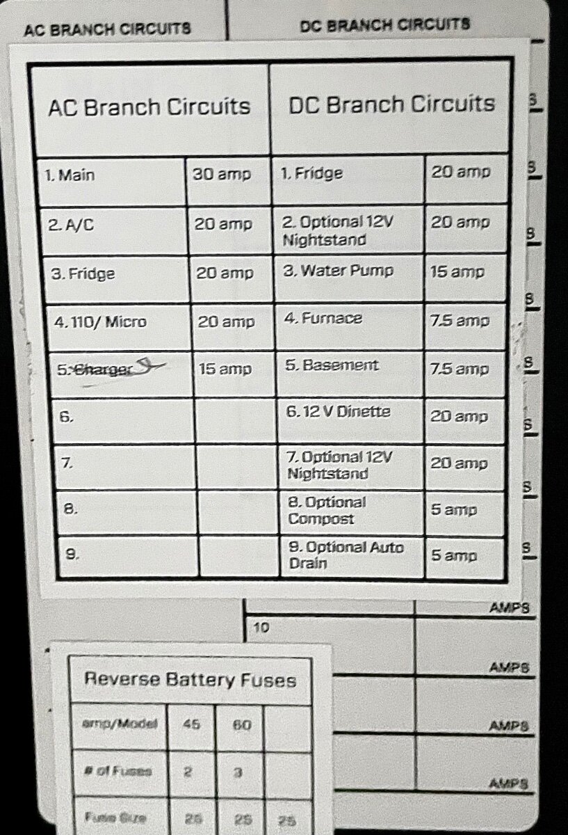
15Amp is blue, and it's for the water pump. Pix of ours so you can read it in a 2019EII Hull 505 Notice that I crossed off the #5 AC breaker for the 12V Charger. When I upgraded to Lithium batteries I replaced our embedded 12V charger with a new combination 2000W Inverter/Charger . I disconnected the wiring from the 15A breaker for the embedded 12v charger to deactivate that circuit.
-
NO BRAKES ; 2019 Oliver Elite II-Hull #448
Galway Girl replied to BoondockingAirstream's topic in Mechanical & Technical Tips
@BoondockingAirstream you may want to watch this before your tech shows up. How to troubleshoot electric brakes. -
NO BRAKES ; 2019 Oliver Elite II-Hull #448
Galway Girl replied to BoondockingAirstream's topic in Mechanical & Technical Tips
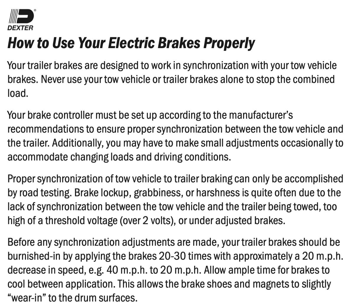
It appears you have brakes that work (from your break away switch test). But your 7 pin to brake connection isn't working. Hoping the RV Tech helps you out and gets it all set up correctly. As an aside to your brake issues....it's important whenever brake assemblies are new or changed to "burnish them" in before full trailer use. I learned when picking up Hull 505 that electric trailer brakes on new trailers must be BURNISHED or heated up to brake them in and seat them to the drums. When we started to pull away I grabbed the controller and squeezed...no brake action. I walked back into the service team and they showed me a page in the Dexter Service manual. They said I needed to burnish my brakes by driving on some back roads on my way to the first campground. I found that after about 30 applications my brakes where really starting to work well. The next morning as we pulled away I dropped the controller back to 5 out of 10 and I had working brakes on our trailer. This is NOT done by the factory that assembles the trailer. It must be done either by the DEALERSHIP selling the trailer....or more likely the OWNER. Hopefully you'll catch a break and things will all be fine after your RV Tech visit. To seat the brakes, Dexter and other manufacturers have a recommended brake in procedure. *See video&
-
Truck Charging Wire location inside OTT
Galway Girl replied to dewdev's topic in Ollie Modifications
Wow...that's an early composting toilet then...we don't have one. That means even between builds the factory might change which wire is for which purpose. -
NO BRAKES ; 2019 Oliver Elite II-Hull #448
Galway Girl replied to BoondockingAirstream's topic in Mechanical & Technical Tips
Oh yes....it does show that on the schematic. Sorry for the red herring. -
NO BRAKES ; 2019 Oliver Elite II-Hull #448
Galway Girl replied to BoondockingAirstream's topic in Mechanical & Technical Tips
The breakaway switch connects the blue wires and the pink wire through +12v side of a 20amp resetting breaker (under the street side rear bench cover). CS
-
What's your hull number. How are you charging them? Are you charging from shore power using the on board inverter/charger? If you're running from a 15 amp circuit plugged into the trailer you may need to change the settings on the charging part of the inverter charger. A little more info will help us troubleshoot. Craig
-
Yet Another Portable Solar Charger Project
Galway Girl replied to Steve Morris's topic in General Discussion
Yes you need a controller for the 2 external panels as the ZAMP connector on the side of the trailer goes through a fuse then onto the batteries. Solar Suitcase Tips and Build Inside this article I discuss how the zamp connector is reverse polarity from other SAE connectors so be certain you wire your adapters correctly. You can buy the adapters on Amazon. Zamp Cable - Zamp Cable from Amazon Craig -
Truck Charging Wire location inside OTT
Galway Girl replied to dewdev's topic in Ollie Modifications
@dewdev that is the 1AMP fuse for the propane/leak detector in our case located under the dinette.