All Activity
- Today
-
We finally got a window (and the courage to drive through PDX traffic) to visit the Oliver dealer in Salem, Oregon. It took about 30 minutes, and the tech seemed professional. Atta boys for the service team We also took a few minutes to look at the new Olivers that were at the dealership. They’re nice, but I suspect we won’t be buying a new trailer. I did like the compressor fridge and lithium batteries, but I don’t think it will be enough to sway us.
-
- 3
-

-

McHitch versus Hitch Ezy
Wandering Sagebrush replied to Wandering Sagebrush's topic in Towing an Oliver
I have not seen or tried one, but they do look interesting. I’ve gone another route for rough terrain and have purchased a high clearance teardrop for my solo trips. The teardrop I mentioned above has a Max Coupler articulated hitch. While it’s nice in rough terrain, I can’t see myself taking the Ollie into those conditions. -
Living on the Northwest coast of Washington we rarely get temperatures low enough to cause freezing issues while in winter storage. It does happen though and the potential for freezing damage does typically raise its head a few times each year while during the winter months. I have been giving some thought to the installation of an electric heater designed to keep warm air moving between the hulls when temps drop into the 10's & 20's. A small, high quality electric heater permanently installed which draws in cabin air and routes it through areas between the lower hulls where plumbing and other temperature sensitive components live could serve the dual purpose of protecting trailer components from freezng and help keep things warmish and dry. I understand this system would only be functional while on shore power. Anyone here designed and installed such a system?
-
If you are interested, here is the link to BB Technical White Paper. https://battlebornbatteries.com/technical-note-on-the-safety-and-design-of-the-battle-born-100ah-positive-terminal/
-

Made in USA leaf springs
John Dorrer replied to Mountainman198's topic in Mechanical & Technical Tips
Just received our Alcan Springs 5-leaf with heavy duty hardware. We will be having them installed as 4-leaf. Scheduled for first of June around a short Indiana trip. Will do the two 50 mile drives same day and they will re-torque, and then after our Indiana camping trip for the 500 re-torque. -

Water Pump suddenly stopped. What to do?
HDRider replied to DonnaDuane's topic in General Discussion
@DonnaDuane You left us hanging. What was the problem? -
Automatic Leveling for the Oliver Trailer — DIY style!
HDRider replied to Snackchaser's topic in Ollie Modifications
Some people are really smart. @Snackchaser You sir, are really smart. - Yesterday
-

Automatic Leveling for the Oliver Trailer — DIY style!
Mike and Carol replied to Snackchaser's topic in Ollie Modifications
Interesting! Are you starting a waiting list for your production model? 😁. Mike -

Automatic Leveling for the Oliver Trailer — DIY style!
Snackchaser replied to Snackchaser's topic in Ollie Modifications
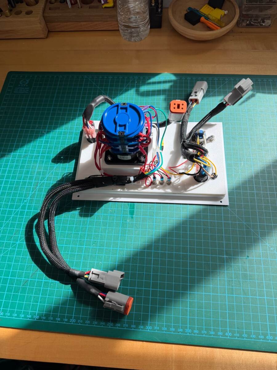
Custom Automatic Leveling for the Oliver's Barker Jacks — Part 2 Here is some more detail of the automatic leveling project as it transitioned from an idea to a working prototype. The project evolved from concept with safety and trailer protection as core design priorities. Limitations were built into the software including current-based motor cutoffs and maximum leveling offsets to prevent over-stressing jack capacity and minimized frame stress. On the mechanical side, the design incorporates fail-safe circuits, redundant shutdown methods, and four levels of overcurrent protection. A side benefit is the electronic monitoring of jack condition where abnormal current can reveal lubrication issues, mechanical wear, or circuit degradation before they become catastrophic failures. First step was writing a program script with open source Arduino software, and then uploading it to an ESP-32 microprocessor. The ESP-32 is basically a $10 miniature computer with programmable memory and integrated WiFi module (I might develop a Leveling App later). It receives inputs from a Inclinometer and two 50 amp current sensors, and it sends outputs to a status LED, a piezo buzzer for audible tones, and a 8 channel Darlington driver that converts digital inputs to 12 volts for relay coils. Six 30/40 amp Bosch style automotive relays are wired in an H-Bridge configuration to run the jack motors in forward and reverse. With a basic design plan and software, a test board was needed for proof of concept before anything could be installed in the trailer. The test board included potentiometers to simulate jack current, and LEDs to indicate the jack's up and down movement. It had a status LED, an isolation relay LED, a piezo electric buzzer, and a circuit board mounted with the microprocessor, inclinometer, drivers, and power supply. These standalone plug-in modules are wired together with soldered jumpers on a generic printed circuit board. Testing resulted in many design and software changes as the bugs were worked out. During this time it became evident that the tongue only needed the inclinometer for leveling, no current sensor required. I also realized that the jacks should be run in decreasing intervals with a limited number of leveling attempts before timing out. Another improvement was to run the jacks uninterrupted in free air until they were firmly seated on the ground for stabilization — before starting incremental leveling movements as needed. Current values are easily adjusted if more or less stabilizing pressure is desired. Testing found a flaw with the inclinometer. Thankfully they came in three-packs and I replaced them because they wouldn’t stay calibrated. The inclinometers have accelerometer and gyroscope functions, and it turned out that the accelerometer has known drifting issues. After turning off the accelerometer in the software, it worked great! In the end, the Arduino script grew to over 1,000 lines of code. With a lot of trial and error, a sequence of operation was developed: When the Level button is pressed, the rear jacks lower without interruption until they are seated on the ground in a firmly stabilized position (phase 1). If the trailer is level at this point, then there is no further action and an audible “happy tune” indicates successful level was achieved. If the trailer is not level after phase 1, then the left or right jack is cycled in intervals starting at 1.5 seconds (~1/2” travel) depending on how close to level it is. As the trailer gets closer to level, the interval shortens to account for coasting and fine adjustment to within 0.2 degrees of level. During the roll leveling sequence, a pitch limit of 5 degrees prevents the rear jacks from inducing too much pitch. It's a safeguard that temporarily interrupts roll leveling while it moves the tongue jack to bring pitch back within limits. Phase 2 pitch leveling begins, if needed, after roll level is achieved. When roll and pitch are level, the “happy tune” is played. The system allows up to 20 level correction attempts per axis before declaring unsuccessful leveling with a “sad tune.” The operator can stop the leveling at anytime with the On/Off switch or by re-pressing either momentary button. The “Retract” function proved difficult to program because of the mechanical clutch. Originally it was programed to shut off when the mechanical clutch actuated in the parked position, which is 13 amps. This didn’t work because the jacks had a current spike when coming off load, and there were oscillating current spikes during the clack-clack of the clutch that caused shutdown before before a clack was heard. These spikes hadn’t shown up in the time compressed current chart, but they were picked up by the current sensors. This was resolved in the software with a current delay when coming off load, and a longer delay when the clutch actuated so a few reassuring clack-clacks could be heard for audible confirmation that the jacks were fully parked. The leveling system was designed so that the jacks manual switches could remain fully functional. However, the H-Bridge relay configuration reverses the motor polarity for the up or down direction, and that could cause a direct path to ground when using the manual switches. To prevent this, I used a normally open relay to isolate the ground when the leveling system is not being used. I used a single 250 amp generic lawnmower starter relay on a common ground bus for all 3 jacks. It seemed reasonable. .. what could possibly go wrong? Hope this is still interesting…Cheers! Geoff Please excuse poor photos, I just didn't take very many!
-

Automatic Leveling for the Oliver Trailer — DIY style!
BigTexas replied to Snackchaser's topic in Ollie Modifications
This is brilliant! Oliver already makes it pretty easy to level the trailer. But if I wanted to make my camping friends (even more) jealous, I would build this and watch them grimace with envy. -
.thumb.jpg.e34bf01ef7f7d5e99ad31856d45afbeb.jpg)
Automatic Leveling for the Oliver Trailer — DIY style!
CRM replied to Snackchaser's topic in Ollie Modifications
Exactly how I do it. -
 pmcneal2858 joined the community
 -
Automatic Leveling for the Oliver Trailer — DIY style!
John Dorrer replied to Snackchaser's topic in Ollie Modifications
A 2' level does the job. Set on the rear bumper for side to side. Add levelers as needed, chock and disconnect. I take the 2' level up against the belly band and raise or lower to get level Actually a good idea to have the tongue raised slightly to allow flow in the tanks toward the back. Very simple -

Seeking Feedback on Tongue Box Design
dewdev replied to OffWeGo's topic in Mechanical & Technical Tips
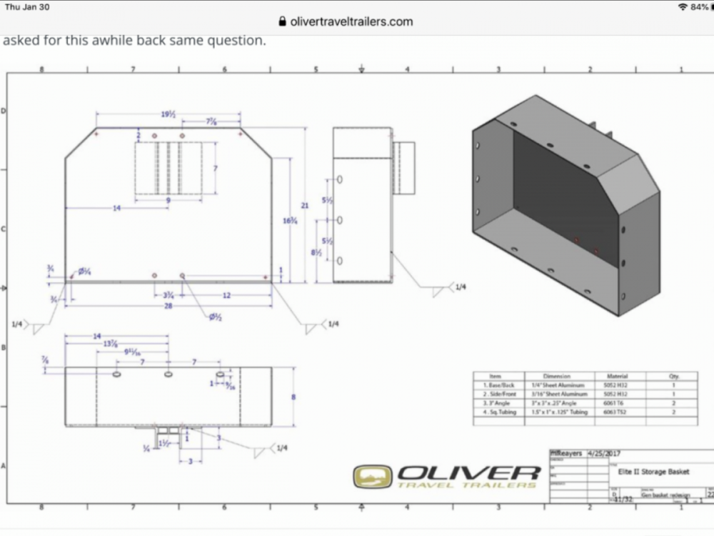
Not sure if this is of any help, but I have attached the dimensional drawing for the Oliver front box, FYI.
-

Automatic Leveling for the Oliver Trailer — DIY style!
DanielBoondock replied to Snackchaser's topic in Ollie Modifications
With a 7k trailer, if it was held only by the jacks (or if one jack lifted the tires) they'd be at 2,333 lbs each and the 2026 Barker 3000 VIP jack is rated to 3k lbs. So the limiting factor is the rear jack mounting. It's not nearly the same as the the front jack I think, but without looking (I'm not at the trailer) I think it might be attached to the frame? Oliver tends to over engineer at any rate which I approve of. Also unknown long term effects. Anyhow that's a crazy nifty solution, nuts to have that level of automation in a small trailer like this, but I think its great. What I like even better is that water valve panel, as beautifully done as it is the under bed solution is a PITA. -

Automatic Leveling for the Oliver Trailer — DIY style!
OffWeGo replied to Snackchaser's topic in Ollie Modifications
Impressive! Thanks for sharing. -
Furrion Chill Cube – Product Review and Installation
OffWeGo replied to jd1923's topic in Ollie Modifications
It's getting up into the high 80' here this week. We're going for a one week trip next week so I'll be testing things out. The big trip this summer starts out with a week in Cade's Cove, TN, where there are no hookups. This will be the real test of running the Chill Cube off the inverter. I'll be doing some test runs at home this week to see how long the ac can run on the (640 ah) batteries. With the unit on 50% (gear mode) and low cool its seems to be near 250 watts! -
Seeking Feedback on Tongue Box Design
OffWeGo replied to OffWeGo's topic in Mechanical & Technical Tips
Thanks Don, excellent feedback! -

Seeking Feedback on Tongue Box Design
dhaig replied to OffWeGo's topic in Mechanical & Technical Tips
@OffWeGo, I reviewed the sketches you provided for the Front Storage Basket and offer the following comments: Placing the unit in front of the dog house will move you 26" away from the cover on the doghouse. This will likely make removal of the doghouse cover difficult, if not impossible for one person when propane tanks must be refilled. To remove the doghouse cover on my 2022 LEII I straddle the tongue of the trailer and am able to reach the handles on both sides to lift it. Some clearance space will be needed between the front of the doghouse and the rear of the storage unit for clearance of the doghouse cover when dis-mounting and mounting. If the top of the storage unit is hinged at the rear, space will be needed to avoid hitting the top of the doghouse. No details are included to show how the storage unit is to be mounted. The indicated mounting positon places the storage unit on top of the fiberglass covering the trailer tongue. The fiberglass would need to be drilled for passage of mounting bolts. You would likely need spacers to keep the storage unit from resting on the fiberglass and potentially cracking it. You would need to tap into the aluminum frame members or use long "U" shaped bolts to secure the storage unit to the frame. As I recall, Oliver uses long "U'" bolt to secure the front storage tray they offer as an option. The storage unit design has a lot of doors (2 side, 1 front, 1 top). This presents a challenge for the frame of the unit to have sufficient rigidity to support the doors. To have sufficient rigidity you may have little choice but to have a square tube inner frame. Having the tubing presents an obstacle to installing and removing the generator, as you have noted. Also, securing all of the door to prevent theft will be a challenge. The top will need a gas cylinder or other support to hold it open, I had an outdoor grill stand fabricated from stainless steel to support a 200 lb grill. My initial design used square tubing to be clad with stainless steel sheeting. I took the design to an experienced fabricator, who recommended eliminating the square tube frame and building the stand using stainless sheet only. This change produced a much better result. There are storage areas on each side of the grill and they have stainless steel doors. The unit is quite stiff and strong. If you are interested I can provide photos of the details. How is the removable shelf to be supported? "L" shaped brackets mounted to the inside of the unit could work. The mounting method could be either bolting or welding. Your sketch lists routing of the power cable from the generator to the shore power connection on the street side of the doghouse. You might consider attaching a weathertight electrical box containing a 15 or 20 amp outlet on the exterior of the storage unit, with a short cable running through the wall into the generator. I suggest making a short cable that would connect from the weathertight box outlet to the shore power inlet. How accessible are the pull starter, choke and controls on the generator when in the storage unit? I have used small Honda generators before and they are usually relatively easy to start, but I never tried starting one in a confining box. I suggest you reconsider having the generator mounted in a storage unit on the trailer tongue, for several reasons: Mounting the generator to the trailer frame will likely transmit vibrations along the frame which will be noticeable in the cabin. The same concern for noise. Having the generator exhaust so close to the cabin presents a danger of infiltration of carbon monoxide into the cabin. Overheating is likely to be a problem running inside the storage unit, even with all of the openings. Additional tongue weight may become an issue. I don't know the tongue weight limit for your Tundra. The generator, storage unit and chocks could add 60-75 pounds. I try to locate our generator as far as possible from the trailer, considering neighbors, wind direction, etc. I use a 25 foot propane hose to connect our generator to the low pressure propane connections on the front and rear of the trailer. I elected not to install any type of cargo carrier on the trailer tongue, primarily to keep the tongue weight within the limits of our tow vehicle, a BMW X5 35d (diesel). I did not like the cargo tray offered by Oliver- too small to meet our storage needs and too difficult to secure. Instead, I installed a rear mounted cargo carrier. The generator, a grill, chocks and Starlink case are accommodated. You can find a write-up on the details here: How To Install a Rear Cargo Carrier on an Oliver Legacy Elite II. Good luck with your project! Regards, Don -

Water Pump suddenly stopped. What to do?
GarryandKristi replied to DonnaDuane's topic in General Discussion
Had an issue with our pump (2018 LE2) just a few days ago. Thought it would likely be one of the switches. These are (effectively) double throw-single pole switches (there are 3 unused connectors so switches are technically double throw-double pole) in cabin and bath with 2 traveler wires with +12 v in the middle spade connector, so if one combination of switch orientation between the cabin and bath didn’t work the other should of it’s a traveler spade connector disconnecting. I first looked visually at the 15 amp fuse under the dinette and it looked ok. Next morning I tried the different water pump switch combos between cabin and bath to no avail. The switch leds were off all this time. I then pulled the fuse to check for continuity on my multi-meter and it checked out ok. When reinstalling the fuse I heard the pump actuate and the led flickered a few times before turning solid. I think the issue was likely the pressure switch. There are 2 red leads at the front of the pump and I think these are are on opposite poles of the pressure switch and the switch had gotten stuck. The ground wire connection seemed ok so I am convinced it was not the switch spade connectors being loose. Anyway I would have never thought pulling and reinstalling a fuse would remedy the issue. The switches must have been in the on combination for this to happen. Not sure how the leds are wired as they should be lit in either state of the pressure switch (connected/disconnected). -
 Brad Koster joined the community
 - Last week
-
 Not if they had the bathroom drain valve closed.
 -

Help: Shower filling up with Kitchen sink water. How?
jd1923 replied to Wayfinder's topic in Mechanical & Technical Tips
Thanks, Bill & Martha What Mike explained in the first paragraph of this post is he was pumping water into the black tank, as part of a cleaning process. He got distracted and left the water running. In this case the toilet bowl dump valve was closed. So the water could not go up into the bowl. The pressure from the hose after filling the tank to capacity, would then push the water up to that vent junction and into the gray waste system. This is an abnormal use-case where this occurred. Operator error, and hose pressure forced the overflow. Normally, this would not occur when operating the Oliver waste systems as designed. -

Help: Shower filling up with Kitchen sink water. How?
Townesw replied to Wayfinder's topic in Mechanical & Technical Tips
@jd1923 It hasn’t happened to me but it has happened to at least 3 people in the following thread https://olivertraveltrailers.com/forums/topic/3447-left-black-tank-clean-out-hose-on/ -
Help: Shower filling up with Kitchen sink water. How?
jd1923 replied to Wayfinder's topic in Mechanical & Technical Tips
I'm having trouble seeing how this could occur. But given this "has occurred" in your experience, please elaborate. Wouldn't the toilet bowl overflow first? We had our black tank once right up to the top, tank full and up the neck, 1-2" below the bowl. Had to stop using it until we towed miles to dump tanks. There was no black waste in the gray water. We also had the grey fill once to where it came up on the shower floor. In this case, we dumped some gray while boondocking since this is legal in in the SW National Forest lands when 500 feet from others and water sources. In neither case did waste of one kind go up the vent and into the other. I'm failing to see the physics that would cause water to get up to knee height which I believe is the approximate height of the sewer gas vent junction. Let us know. Thanks -
Help: Shower filling up with Kitchen sink water. How?
Townesw replied to Wayfinder's topic in Mechanical & Technical Tips
Cross-over of water from the black tank into the gray tank through the common vent absolutely can and has occurred. More than one owner has attached a black tank flush hose, turned it on and forgotten about it. When the black tank fills water rises up the black vent and spills over into the gray vent. If the shower drain valve is closed the water comes up through the shower drain. If the shower drain valve is open the gray tank fills and then the water comes up through the shower drain. -
Help: Shower filling up with Kitchen sink water. How?
jd1923 replied to Wayfinder's topic in Mechanical & Technical Tips
Yes, as Mike explained and as John wrote nicely in two short sentences. Perhaps you did not see bubbles in the gray waste since there was enough gray water to break down the soap, kill the bubbles, which did not occur in your black waste. For a fact, black and gray waste are two independent systems, except for the venting of sewer gases as @Townesw illustrated above. However, the vents are at a height, a couple of feet taller, where the cross-over of liquids simply could not occur. Gray water would fill the shower floor and overflow into the cabin well before the height of these vents could be reached.