
Geronimo John
-
Posts
2,379 -
Joined
-
Last visited
-
Days Won
67
Everything posted by Geronimo John
-
nice!
-
Step One: I agree with Tom and Doreen's post. Step Two: If you put a volt meter on each side of the breaker and use a common ground for the - lead, you can measure the voltage drop thru the breaker. If it is nominal, then the next step I recommend is using your brake temperature IR gun to scan all the 4/0 terminal temperature. They all should be about the same. If you find one hotter, then make the system safe and clean that terminal. Then retest a second time. Clean the next hottest one and retest. Repeat until you see all of them about the same temp. Good luck. GJ
-

Made in USA leaf springs
Geronimo John replied to Mountainman198's topic in Mechanical & Technical Tips
Many of us know that feeling. We purchased ours from Hawaii having never seen one in person. But what we, as you, did was to really study the tone and helpfulness of the members here on this forum and the "SOB's" (Some Other Brands) as well. At the time, and still to this day, I think that the owners sell more trailers than OTT does themselves. No other brand came close in this regard. After our purchase I had an opportunity to go to the factory tour and instantly fell in love with our decision. As a technical we all know that machines need maintenance and TLC. Also that some times tweeks to the foundational design of a machine is necessary. WIth OTT, we have seen a few upgrades, a few changes, and very few OOPS. And the number of OOPs is very small. However over times things change. The two biggest changes I have observed in the past ten years from an owner's perspective likely are the percentage of owners taking their OTT's boondocking further into the wild and running heavier than earlier years. The impacts are higher "G" forces and typically +/- 6,000 pound weights on the suspension 100% of the time. Both of these changes are not OTT fault. There is clear evidence of premature spring failures from OTT owners having road side spring failures, and dozens more finding that their springs flatening out way too early in what should be a normal spring's useful life. So a design change is needed. I believe from history that OTT would not ignore such failures without concern and would be monitoring our experiences. I also would wager one of Art's famous home brews that they are looking at an upgrade standard spring to the 2400 # Dexter four-leaf springs and an option for a "Boondocker's Heavy Duty" suspension package featuring the Alcon type of 5 leaf. Those options both make good common sense. Good news is that OTT takes a lot of care and time, as they should, before making such changes. In that regard it would smart to keep track of the owners who have changed their springs and to monitor them in the normal duty and heavy duty class. In doing so to get specific data as to the pros and cons of their spring choice for their use. If I was running their quality control team that is exactly what I would be doing. One needs data to to make data driven decisions. GJ -
Made in USA leaf springs
Geronimo John replied to Mountainman198's topic in Mechanical & Technical Tips
Per the above posts, even that group is seeing failures. Time for OTT to wake up to the reality that the owners want a change to a stronger spring. For JD's sake I'll not go further on that! LOL GJ -
Made in USA leaf springs
Geronimo John replied to Mountainman198's topic in Mechanical & Technical Tips
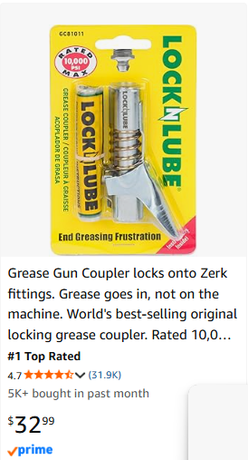
The #1 Ollie Tool I purchased was the Lock-N-Lube lock on grease gun fixture. It is amazing and certainly helps. I had a new ole style grease gun and just added the below to it. Love it. With it I did not need to go right angle. I liked the 45 degree ones better. Especially with the below. When I need to replace my grease gun, I'll pay the bucks for the Lock-N-Lube version for sure JPR
-
Alcan Springs Quote for Jan-2026
Geronimo John replied to Wayfinder's topic in Mechanical & Technical Tips
You are on the right track in attacking the bolt head end. Certainly the approach in your above quote will work. But the Hex Nut Capture Washer would look and perform better. And they are dirt cheap. See my DIY. DIY - Dexter EZ-Flex Center Bolt Spline Repair (20 APR 2024).docx -
Alcan Springs Quote for Jan-2026
Geronimo John replied to Wayfinder's topic in Mechanical & Technical Tips
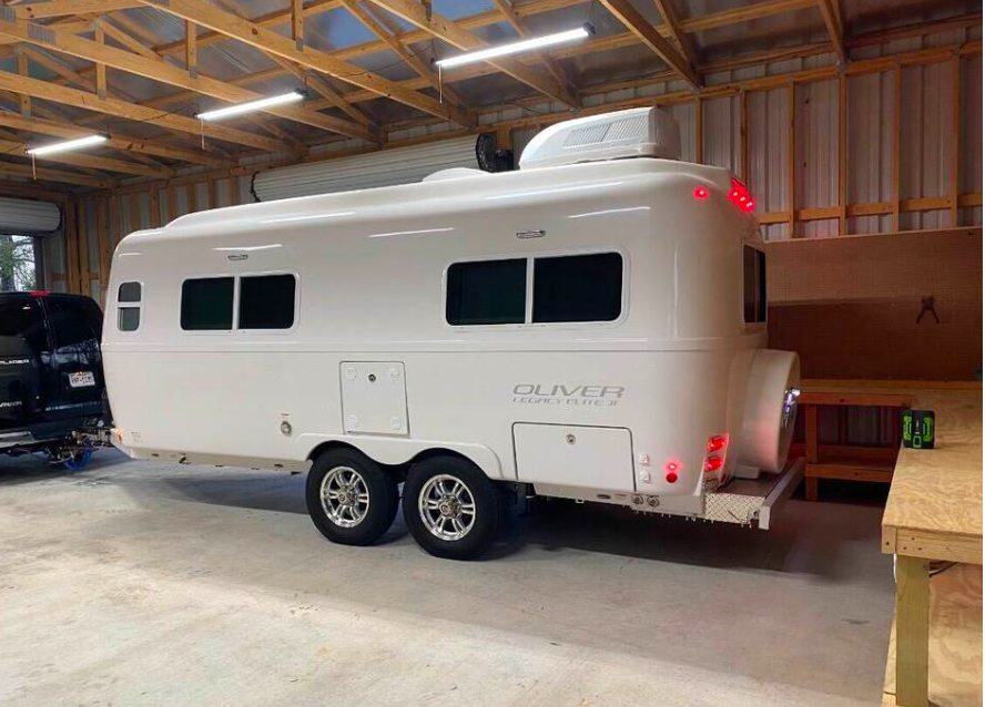
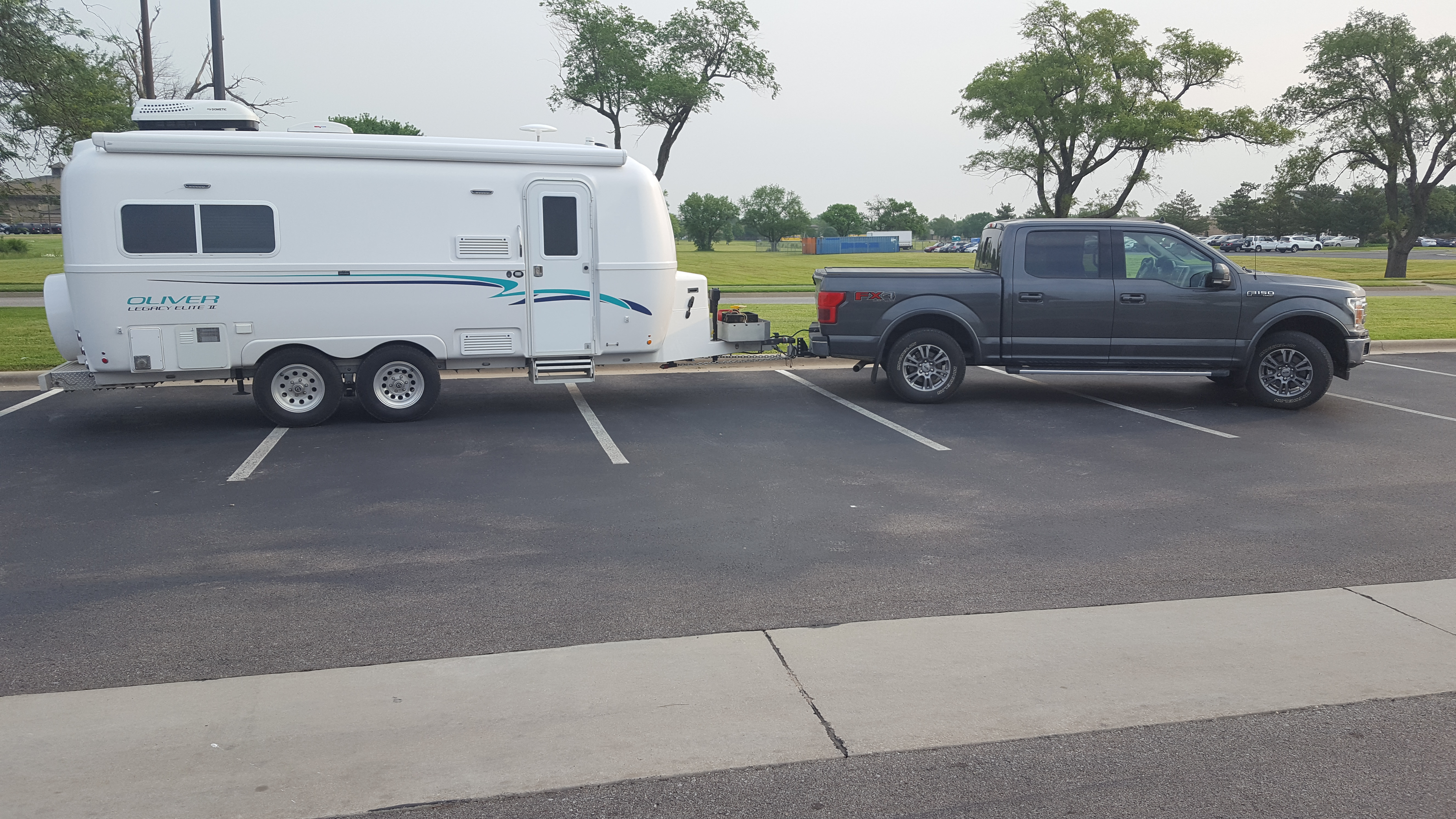
PS SWEET BARN! And Ollie too of course! GJ
-
Alcan Springs Quote for Jan-2026
Geronimo John replied to Wayfinder's topic in Mechanical & Technical Tips
Roger, I have a very simular issue but harder. If the approach is level, carefully checking clearance is easy. Mine had a foot tall "ramp" that would kick the rear of our Ollie up about 5" as I backed into the lean-to enclosed area. I removed the gavel floor took out a couple inches of dirt and re-graveled. Still no go. Then I hauled back all that dirt, and a bunch more, and made an elevated area 20' long and 10' wide "Table" in front of the barn door. So I back Ollie up onto the "Table" and then it was an easy back into the "Ollie Cave". Hope yours is a level entry. GJ -
Alcan Springs Quote for Jan-2026
Geronimo John replied to Wayfinder's topic in Mechanical & Technical Tips
Had problems with trying to include my DIY attachment. Trying again. GJDIY - Dexter EZ-Flex Center Bolt Spline Repair (20 APR 2024).docx -
Alcan Springs Quote for Jan-2026
Geronimo John replied to Wayfinder's topic in Mechanical & Technical Tips
DIY - Dexter EZ-Flex Center Bolt Spline Repair (20 APR 2024).docx Yes for splined bolts you MUST do so. Yes, that "someone" was me. Here is my DIY to fix it. Hex Bolt Capture Washers. Only alternative solution would be to replace the tangs and that is much more invasive than the capture washers. GJ -
Made in USA leaf springs
Geronimo John replied to Mountainman198's topic in Mechanical & Technical Tips
Hey JD Looks like I'm lagging behind on posts about springs. LoL Can we lock all spring pages? Just kidding all questions deserve a respectful answer. gj
-
Made in USA leaf springs
Geronimo John replied to Mountainman198's topic in Mechanical & Technical Tips
I beg to disagree for the statement's inclusion of the 1750 rated springs. WAY too many have FAILED to even be considered for use as anchor weights, let alon a 6,000 pound contineous 24/7/365 load plus G-forces. Even Dexter says this. For the life of me I do not understand why OTT continues to ship trailers with these springs. It boggles my mind..... I USED to say for 90% the Dexter 2400's would be a great solution. That other 10% is for the Off-Roader's that put their trailer thru gynmastics on a regular basis. Now I think 85% is a better number as I am hearing of more than a few owners in the 5,000 pounder class that may also skate by with the whimpy 1750's for 5+ years as well. But if I were one of them, I would still go with the 2400's to get a respectable 15 or 20 year life for the springs. I like doing things once to learn, but not repeating when logical to do so. GJ -
Alcan Springs Quote for Jan-2026
Geronimo John replied to Wayfinder's topic in Mechanical & Technical Tips
Yes. The new PB4's raised the trailer about half an inch over the whimpy 1750's. I am "critical" on the trailer height where I store my Ollie. As it worked out it was no problem. Good Luck! GJ -
Made in USA leaf springs
Geronimo John replied to Mountainman198's topic in Mechanical & Technical Tips
Wow. The first three statements encapsulate my position of opposition for 90% of OE2 owners to the 3,000 pound springs. For most owners they are "Over Sprung". But the 1750's for all of us running in the 6,000 pound class I have advocated long and hard that those springs are "Under Sprung" as they are loaded 100% of the time and are failing. For a new trailer, I would monitor the rear ends of the OEM 1750's and push their replacement out 4 or 5 years. If you see any flattenng of the rear ends, time to replace them. Also as a 50 Year Mechanical Engineer here and 3 independent Dexter Tech's determined that the middle ground between the 1750's and the 3,000's... The 2400 Dexters was a logical choice. They have been doing just fine for the last 20K miles or so..... WIll be putting another 9K this summer. For every one, it is wise to inspect your springs at the end of each season. If any flattening is observed, you would have the off season to replace them as you see fit. GJ -
Missing screws on cabinet cabinet drawers
Geronimo John replied to Gliddenwoods's topic in Mechanical & Technical Tips
Since two of the screw holes are compromised, two new ones in the other locations will likely work another four years for you. All depends on how heavy you load those drawers, and how rough and long your roads to boondocking camp sites. Personally I try to do things once and done. We load our pantry very heavy. Had to install stiff legs under those shelves and 3X the number of shelf strap hangers. I understand that OTT improved the setup in later year OE2's. But keep an eye on those shelves as well. Good luck GJ -
Missing screws on cabinet cabinet drawers
Geronimo John replied to Gliddenwoods's topic in Mechanical & Technical Tips
I think you are talking about the kitchen cabinet drawers. If so, the below applies: It is a PITA to have to pick up the stuff that was in the drawers and you find it in the isle rolling around after a long day of travel. I KNOW your pain. The under drawer hardware attachment is great until it is not. Basically the screws into the drawer bottom come under shear when you hit a bump and turn towards the right. Over time the connection fails when you hit a bit bump or turn. I had two of my launch the contents. Good news is there are three things you can do, and I have done all three of them: A. Add a John Davies drawer strap to the two sets of kitchen drawers. My DIY of his idea is below. B. Pull the drawers and thru drill a hole and use really small bolts with washers and Nico's to thru bolt the hardware in place. I used four per drawer bottom. I put the nylocks and washer below, and the smal head and washer above in the drawer. C. Tightbond the underside drawer bottom to the side walls. Granted I have never heard of the OTT drawers coming apart as they are well made. But I figured while I had the drawers out and upside down, why not armor plate the edge to bottom seams. A little summer sunshine dried them for reinstall in less than an hour. Hope this helps. GJ DIY - Galley Drawers Straps by John E. Davies.docx -
Sorry JD, I'm not even going to bite on that one..... Maybe you should re-read all 27? pages of that thread. LOL GJ
-
First, I very much enjoy reading your posts. Please do keep questioning and pushing the envelope in an effort for you, me, and others to truely understand the "WHY" question. Glad to hear you are ditching the 1750's. Doing so is half the quest. The other half is deciding "What spring best suites our use of our OE2's"? For what I believe is about 10% of owners, clearly the answer is the super strong and reliable Alcan 5-Leaf springs. For the rest of us it is prudent not to "Over-Spring" our suspensions. The obvious choices are either the Dexter 2400 four leaf or the Alcan four leaf. If you are a 10%er that often puts their OE2 into structural gymnastics, great get the 3,000 pound Alcons. If you don't live off-road then the four leaf is your best choice. If you are budget inclined, as I and others are, then the Dexter 2400's is the answer. But if you have the spare cash then why not go to is the Alcan 4-leaf springs. I have to admit that I have never heard someone use the words "Wussie" and "Oliver" in the same sentence. For sure got a LOL out of me on that one. I get your thought line though. Bottom line is that EVERY design has a life span. Air Stream's do in fact pop rivets and have upper cabinet issues when stressed over time. Their owners tend to not be out boondocking on regular basis. Likewise, stress an Ollie suspension enough and one will see the impacts as well. I think Bill summarized the situtation well: So sure we all at times put undue stress on our hulls with no worries. And I think that our hulls are "NEAR" bullet proof. So we can do so for a long time. But it still is smart to go more gentle when we can. Especially for the electronic's, refergerator, glassware, the ton of stuff in our wire shelves in the pantry, not to mention the frame, battery box, ............. etc. Again thanks for your posts! John
-
Short Version: Springs because dozens of us have had them FAIL. Axles because a boat load of us have tons of miles on the 3500 Dexters, and the cost of replacement of the brake assemblies is insane, and besides we want the braking power of the 5200's. None of which involve tire pressure. That topic was started by John D, and I got the facts presented to OTT and they have since reduced their recommendations accordingly. GJ
-
I can assure you that the fiberglass does flex. As do the frames. Granted it is the best on the market bar none. We have seen evidence here in this forum of frames being damaged, as well as structural supported components as well. No one can say for sure that the PSI number or some springs being oversprung CAUSED anything. But our trailers are not totally bullet proof. They can, and have, failed when stressed beyond their design limitations or due to improper actions or choices by owners, or OTT during manufacture. Either way, having some good common sense about how much punishment we want OUR trailer to experience in it's life is just a smart concept to be open to. To that idea, tire pressures and diameters, spring rates and axle weights ALL impact the G-loads our fiberglass hulls endure. Frequency of stressors is also a not yet discussed element of the puzzle. GJ
-
So you are saying that one does not need or should use 60 PSI. But you use 40. Which is what I recommend as well. Just saying your quote above could lead more than a few of us astray. To be clear you and I both recommend 40 PSI. Right? GJ
-
Spot on! I suspect most of us have the AFE concern as well. You sure made me smile on that one! GJ
-
60 PSI? Sure if they like to un-necessarily pound your trailer frame and contents. Oh and more recent, the not so good pounding to the battery box. I had to tell Cray Horse to mind his own business when he wanted me to mention what the spring selection can do in addition to the above. Oh my when will he learn....
-
Thank you for the visual presentation of tire pressures by the major tiret companies. We all should know our trailer tire loads and the tongue weights. Only the trailer tire weights should be used with your charts. For our OE2, with a total weight of 6,000 pounds and a tongue weight of say 600 pounds my four tires are carrying just 5400 pounds. That's 1350 pounds each. Of note in your charts not one of the mfg's have a weight/pressure anywhere close to what most of us are loading. Common practice therefore is to use the MFG minimum recommend tire pressure, either 35 or 40 PSI depending. I know we are all tire experts. Or are we? I run michelin's and the listed minimum for their chart is 40. Why is anybody running 50+ any more? I guess they are special and have more experience than the tire manufacturers. Or not. GJ
-
Can you imagine the carnage that would result on a mountain road, on a hair pin curve, going down hill.... if that center bolt fell out? EZ Flex floppin around down by the tires, causing the axles to imediately be out of alignment flipping one way then the othe being only held back by two shackle bolts fore and aft on one side...... for me the one word answer is "carnage". BTW you are not alone on this topic. PM me if you want the back story. GJ