
Geronimo John
-
Posts
2,379 -
Joined
-
Last visited
-
Days Won
67
Everything posted by Geronimo John
-

Inspectable Item: Propane Area
Geronimo John replied to Wayfinder's topic in Mechanical & Technical Tips
Time for a left turn on this topic. The more I ponder my propane system, and the way that I use it, I'm questioning why I want or need an auto switch over valve. Rationale: I don't ever use the auto switch over part of the device . I want to know when I have an empty tank. It is a single point of failure. It is expensive to replace Why not just buy two regulators and two 18" hoses, attach oneset to each tank, and "T" their outputs to the supply line going into Ollie? Use one tank at a time. When it goes dry, open the small hatch and shut off one tank and open the second tank's valve. 100% redundancy with less points of failure for about the same cost. Your thoughts? GJ -
Inspectable Item: Propane Area
Geronimo John replied to Wayfinder's topic in Mechanical & Technical Tips
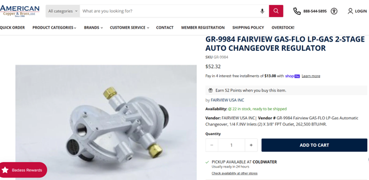
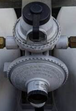
Drats you are correct. It appears that the American Copper and Brass have their wires mixed up. They are selling these two auto change over valves. Their left one shows 245KBTU and the one on the right is their 345KBTU model of another mfg. . Gut the Fairview Fittins and MFG web site says that the GRF9984 is a 345 KBTU model as I posted previously. The Fairview web site says that the GR9984 is rated at 345,000 BTU. Go figure????. Here is the link to the full manual: https://olivertraveltrailers.com/wp-content/uploads/oliver-university/Component_Manuals/Propane_Regulator/Fairview-GR-9984P-Propane-LP-Regulator-Manual.pdf GJ
-
It looks like your Ollie and those winding roads got a lot of snow and several days of hard freeze too. I hope that you will be able to get back safely after the roads get cleared and the thaw allows. Glad you reached out to optimize your rig from being damaged. We all wish you a safe return to your Ollie. GJ
-
Inspectable Item: Propane Area
Geronimo John replied to Wayfinder's topic in Mechanical & Technical Tips
JD: Your regulator may be undersized for the load. Past posts indicate that the gas regulator size likely should be in this range: · The OEM Hull 505: GR-9984XF with 345,000 BTU · Possible Smaller Replacement Part if above is not available: GR-9994XF has 262,500 BTU If you are using a high demand outside stove, grill or fire ring especially with the furnace running; then for sure go the larger regulation. Hope this helps with the moonlight harmony you are getting from your regulatior. GJ PS: The Fairview gas regulators are designed in USA and made in North America. I have purchased them from American Copper and Brass for a lot less than most posted prices on the net. Worth checking them out. -
The "Where do we go from here" statement is on point. If Dragon Fly is not going to honor their warranty without fees, then the answer is: Class Action. I am starting to think that Dragonfly took the Ford approach to Phasers and not the Toyota approach to their EcoBoost head problem. GJ
-
Local web page to search Oliver forums via Google
Geronimo John replied to Wayfinder's topic in General Discussion
Thank you Zodd! I was starting to get a headache with all the above stuff flying by me at Warp 10. I'm glad Chris, JD and Ollie are on top of this for us. I'll remain confused and happy, GJ -
Winterizing in below freezing temperatures
Geronimo John replied to RVK's topic in General Discussion
JD Unless I'm messing up my boat terms: The boondocking port is close to the furnace, aft starboard. The fresh water and city water are aft port side near the outside access to the basement. But you are correct in ensuring that the furnace (vs. space heaters) was being used. It circulates air in the basement and helps prevent problems with freezing. However there is a limit to how cold it will do so. Something that I'll hopefully NEVER NEVER even come close to knowing first hand. See video posted on the other cold related thread. 🙂 GJ -
I have a tough decision on this beautiful blue sky day in Hawaii: Go paraglidng or go surf kayaking..... Another tough day for a RoF (Retired Ole Fart)! I’ll not encourage even more flaming arrows by posting a typical blue skies and bikinis picture, but will share my favorite Hawaii weather forecast. Here is Trumpet the Weather Dog talking about our weather in Hawaii: GJ
-
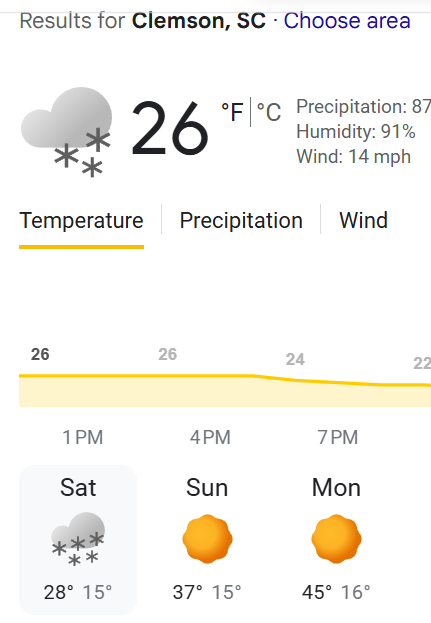
JD: I admit that my living in Hawaii makes me a "Weather Woosie", but the current weather lows at Clemson SC of 15, 15, and 16 degrees are three nights while he was gone each with hard freeze conditions pending. Below cut and pasted for reading enlightenment. So not being winterized while away, with hard freezed inbound, with the furnnace on low..... opening the basement up to the cabin is easy insurance with such conditions inbound. GJ
-
Alcan Spring shackle failure
Geronimo John replied to rich.dev's topic in Mechanical & Technical Tips
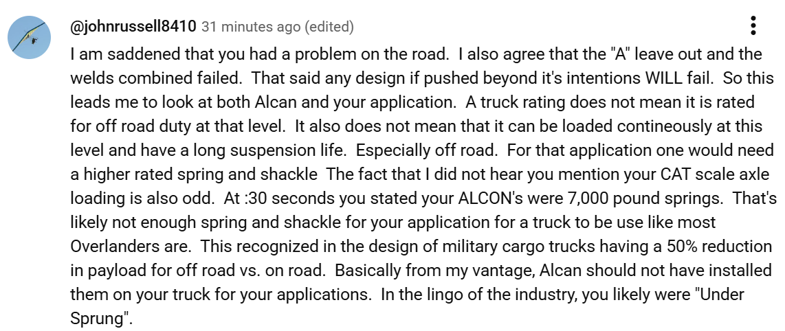
I'm in your court on this one for sure. Yes it was a less than optimal design. Ultimately everything fails if the use is pushed beyond the design limits. I think this is the case for this young couple. The fact that THEY INSEALLED the system from Alcan concerns me. If so, was Alcan advised of the end weight of their vehicle during the purchase or was it a "Send me XXX" and I'll install it transaction. More "Paul Harvey Questins"..... Crazy Horse has warned me about flaming arrows at times seeking me out.... but I can assure you that I don't intentionally try to be such a target. Here is my response to the couple left on their comments section of Youtube. GJ
-
New fiberglass RV manufacturer
Geronimo John replied to Steph and Dud B's topic in General Discussion
Yep! I suspect many OTT owners would like a rubber backed woven vynal floor cover. Suggest you consider asking this to be a new thread under Mods. GJ -
Readers should be aware that you live in AZ. And equally important you generally are in relative proximity of your Ollie should weather turn terrible. Those who have their trailers where hard freezes HAPPENl and can't always get quick response to their Ollie easily..... may want to consider your approach as not being ideal for their location. But for your situtaiton it is easy and effective. GJ
-
Alcan Spring shackle failure
Geronimo John replied to rich.dev's topic in Mechanical & Technical Tips
There have been a few, but they were resolved. In the case of the Overlander and the shackles, it appears that vanity got mixed up in the design with physics. On the surface, it appears that the shackle design with the "A" cutout was a weak point. Alcon's actions to change the design is proof that they thought so as well and commend them for doing so. On the other hand their welding inspector's statements were believeable. My heart goes out to those owners. But who pays is still up in the air. Not knowing the weight of their load on those shackles is not normal for someone who has built the truck. Odd actually. Also not being clear as to how and where they used the truck is not useful. Were they heavy on the springs. Were they abusing their suspension by doing "jumping jacks" with their Overlander. Both could damage the suspension but not yet break it. In time it came apart "for no apparent cause" on the highway. Were there other trucks with the same issue? Bottom line, we need the "Paul Harvy" on this story. ("The Rest Of The Story") GJ PS: I just sent Alcon $$$ for a couple of 5200 Nev-r-Lube's to go with my 2400 Dexter springs. They were $400 less than a great firm in Tulsa. And have the experience on this upgrade for sure. A no worries upgrade. . -
Moving Stabilizer Jack Switches
Geronimo John replied to Tony and Rhonda's topic in Ollie Modifications
If you have a pancake line, don't melt the base! LOL
-
Hoosier: Especially if you down the road you may do the bathroom cabinet hatch, cutting the existing towell fixture caulk and removing the unit for your unique situtation would be advisable. You could temp reinstall eacy week, and next spring permenantly reinstall or do the hatch DIY. Don't forget to keep the the bathroom door open. Use of mag catches has been done by many. But for now, take a cloths hanger (Don't cut it) and just bend it into a long triangle with the hook at the top. Slip the body under the dinette cushion with the coat hanger hook holding the door open. When you get pack, unhook the door and push the coat hanger under the cushion. Easy. As Max Burner's spouse was, mine is loving having the sink storage area all to herself. Happy wife, happy life. GJ
-
YES. Here is Art's (MaxBurner) approach to adding space under the sink. I don't know if he was the first to do so, but I captured his post and used it. it DOES require mod and does provides significant additional storage space. When I did mine, lowered the floor to well below the bottom of the hatch, and extended it as far left and right to gain even more space. Not an easy project, but is one that is not all that hard to do if you are handy. GJ DIY - Art's Bathroom Under Sink Storage Mod.docx
-
You have a very good start. The odds of another deep freeze this weekend is likely 100%. From the forecast, it is already heading your way. I would suggest: · Pulling the bed mattress and vertically stacking them in the hallway. Then pull the fiberglass covers to expose the basement to the cabin interior. · Ditto for the dinette seating and covers. · In the bathroom if you have installed one of these you are golden. Open it. · If not, then consider removing the towel bar cubby from under the sink. · Open the basement hatch in the rear center storage if you have one. Open the wardrobe and bathroom doors. · Insulate the battery box and basement outside hatches. If you have shore power, acquire a small 120V desk fan to circulate air around the opened up cabin. The items above can easily be done very quickly. Of course the hatch takes a lot longer to do. But it opens up quite a bit of storage as a prime benefit. GJ
-
Cold weather rating for RVs?
Geronimo John replied to Steve and MA's topic in Mechanical & Technical Tips
Seems to be a design issue for a lot of us. I removed the adjustable fins on the kitchen and bath vents so they would run wide onpen. Then closed the one by the bed. Applied a dab of cement and it stay's at that setting. I guestimate (another GJ work) that it leaks about 5+% now. With the bed one closed, it forces more air "down the line" . Much more comfy sleeping. GJ -
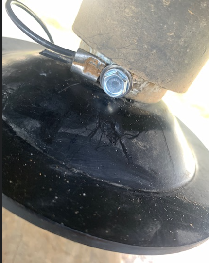
Check your leveling jack feet!
Geronimo John replied to mountainoliver's topic in Mechanical & Technical Tips
Last season I lost one of my "Feet". I attached a small diameter SS cable thru a hole in the dome and put a crimp on it. Then made a tight loop with a crimp just large enough to accept a SS screw into the area just below where the jack sleeve ends. There is just enough room to do so. Have not lost another foot since. If the main bolt under the foot takes a walk, I 'll likely hear the tinkeling as it skips off the pavement. Would need a bolt and some touch up paint to replace. Much easier than having to find a replacement. GJ
-
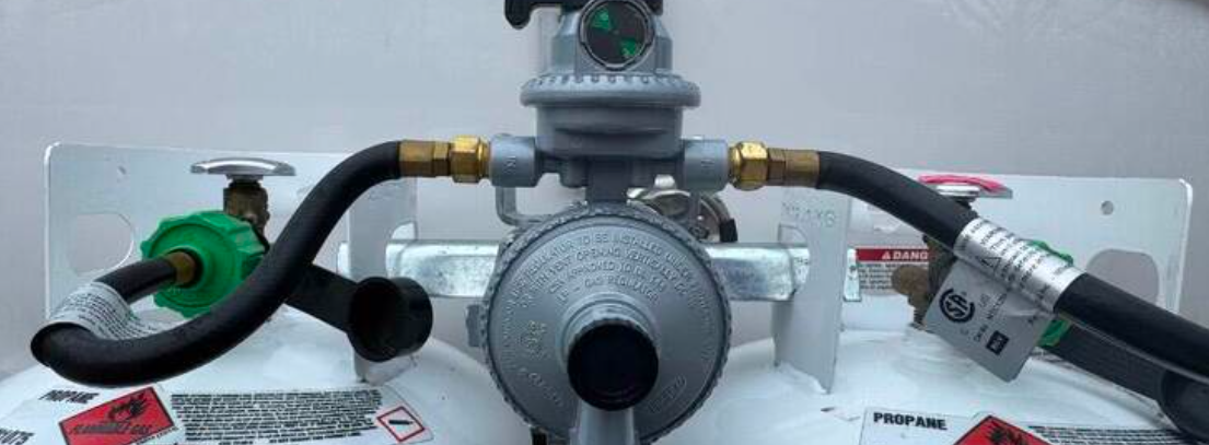
Inspectable Item: Propane Area
Geronimo John replied to Wayfinder's topic in Mechanical & Technical Tips
Ok, I can assume mine is dirty. How do you clean it? -
Inspectable Item: Propane Area
Geronimo John replied to Wayfinder's topic in Mechanical & Technical Tips
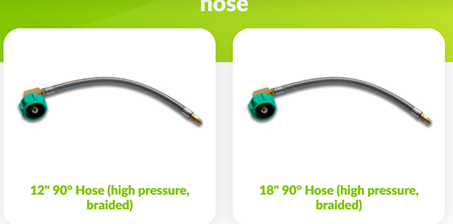
Ok, we have two solutions for the wing nut. If we were to use the Gas-Gear 90 degree hoses we could use these longer ones: Which would allow us to move the regulator forward well out of the way of swinging tanks as we change them. With the regulator moved out of the way (Forward), using one of these for security makes sense now as getting the lock on it would be eazy. Just need a simple bracket to move this forward out of the way: This is sort of turning into a cherry pick the best so far! GJ
-
Inspectable Item: Propane Area
Geronimo John replied to Wayfinder's topic in Mechanical & Technical Tips
i tried that, and did't like the results. So I just added several inches of 1/2" cpvc pipe under the nut to get it up over the obstructions. Either way easy fix. GJ -
Inspectable Item: Propane Area
Geronimo John replied to Wayfinder's topic in Mechanical & Technical Tips
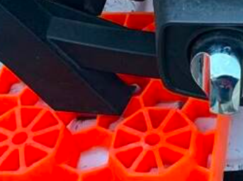
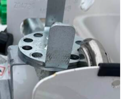
Now that's a good understatement. Your post has generated several concepts that frankly need a relook: The need to have the regulator higher than we had envisionated. (A Geronimo John word) Having enough hose to reduce hose stress especially during tank removal for refill. Using street elbows to get the hose traveling in the right direction from the regulator. Knowing that there is a second set of holes on the regulator. Creative security for our propane gear. Part of the service PITA is that the regulator itself is in the way as the tank installation centerlines are a bit too close. We have room to spare, but all the "OEM Purchased" components are set up for the "standard" set up where space is very critical. We have space to spare. Mount the regulator away from the threaded rod sufficient so as to allow the tightening of the rod handle without hitting or being close to the regulator! And now I'm thinking that the geometry of our OE2 dog house propane hoses and regulators may be space efficient, but it sure does not do us any favors when changing tanks when we have to do a Up and Over maneuver with the tanks. IMO, doing so always is a small PITA. I think we can concoct a better design as we are blessed with space under the hood of the dog house. My assumption is to reuse the tank base, rod, and horizontal tank tie-downbar. Then to focus on the regulator support. From almost 4,000 miles from our Ollie, I'm going to plant a seed to attract some flamng arrows. What if we: A. Modified the regulator bracket to attach to the verticle threaded rod to have two attachment points on the rod and a regulator bracket so as to put the regulator out of the way for service and high enough to be above the liquid level. Double nut one set of the attachment points on the threaded rod to do so. In effect the regulator's location would be fixed. B. Incorporate into the design a simple way to keep the tanks locked down that can be easily removed for service, light and uses a pad lock. C. Increase the hose lengths to facilitate service. D. Use street brass fittings to align the hoses to the direction needed to increase hose bend radius. GJ T Fromthe picture, the 30 pound tanks diameter has reduced a more restricted space for the regulator.
-
Inspectable Item: Propane Area
Geronimo John replied to Wayfinder's topic in Mechanical & Technical Tips
PS: It appears that one of your hoses is relatively new and the other is likely a 2016 OEM. May want to update the older one. GJ -
Inspectable Item: Propane Area
Geronimo John replied to Wayfinder's topic in Mechanical & Technical Tips
Chris: Many of us fully remove the tank hold down bar when filling our propane tanks. I would prefer not to have the regulator support angle above the tank hold down bar. Doing so would subject the hoses to additional stress at every tank fill. That said, I appreciate your warning. I think that I will add two jamb nuts below the tank hold down bar (One on each side of the regulator support angle) to "fix" the location of the regulator thereby reducing stress on the hoses during survice. Do you think that would solve the concern? GJ