Search the Community
Showing results for 'Generator box'.
-
Our Oliver is the first trailer we’ve owned with an EMS, and I’m a bit nervous about using a small generator (Yamaha 1000) for charging if we don’t have enough sunlight for solar and/or truck charging. I don’t yet have a grounded neutral plug, but will build or buy one before any travels. I did check to see if the generator would work, and of course it didn’t because of the floating ground. For info, we have four 6 VDC AGM batteries, and 480 watts of Solar (trailer and Zamp portable). We prefer to boondock, but are not big power users. Mostly lights, Maxfan, and furnace, but we do tow with the 3way refrigerator on DC. Any words of wisdom? Have I missed anything?
-
I found a bundle of wires tucked away below the street side bed at the juncture of the upper wheel well and battery box against the outer shell. My thought at the time was these wires were part of the solar pre-wire setup.
-
 Woke up thinking about this, so briefly researched and confirmed my recollection regarding the Xantrec Freedom XC 2000 in my unit. ‘All Xantrex Inverter/Chargers incorporate an automatic transfer switch. This switch senses when outside AC Power is present and transfers the load from the inverter to the source of incoming power (shore or generator). The unit also automatically switches from invert mode to charge mode.’ I suspect the ATS in the MP2 serves the same function and that an additional TS is required to run an A/C via the inverter.
 -
You received good advice already on the storage box. This subject has been covered in dozens of threads. I wrote an upgrade thread last fall and have read many others before and a few since. There is a lot to consider here, no quick answer. Study the subject, measure your water flow rate, and ask specific questions. You will get good advice here!
-
Got some "Box Envy" going on over here... HA!
-
Honda just released a new 3200watt (26.6 ) amp generator. It is in the same format of the EU 2200i. It will fit under a tonneau cover an should also fit in the front basket. I haven’t measure the basket yet thought. 60 pounds, fuel injection, and all of the same features of the EU2200. It is a little expensive at list price $2999, the 2200 main and companion together are about $500 cheaper than the 3200. If I hadn’t just bought the EU2200i main and companion I would really consider this because of the space savings and one less generator to maintain. The 2 Eu2200i are 4400 watts or 36.6 amps vs 26.6 amps of the 3200
-
Several OTT owners have removed their OEM front aluminum storage box in favor of a larger enclosed one. Lkely one of them would be glad to offer to sell theirs at a reasonable cost plus shipping. GJ
-
I replaced my Zamp PWM CC with a Victron MPPT CC which I installed beneath the street side bed and I had to connect the wiring from the solar panels to the wiring going to the Victron CC. That splice was done behind the original Zamp CC location. And I found that solar panel wiring ran from the original Zamp CC location back to the attic and up into the inner/outer hull cavity and onto the combiner box. It seems to be the same route mountainoliver mentions above. Mossey
-

Multiplus II with PD EMS wiring help
rideadeuce replied to rideadeuce's topic in Ollie Modifications
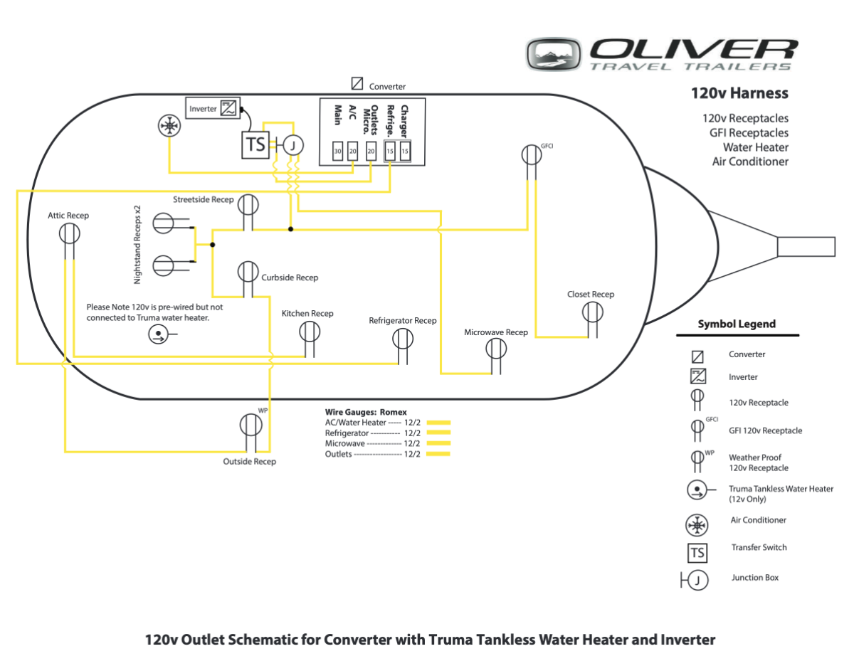
Anyone with a Multiplus II 3000W upgrade able to share how they powered A/C from the inverter. MPII has transfer switch built-in. So the plan is to remove the OEM transfer switch and Jxn box. Then connect the AC IN and AC OUT to the MPII from the old junction box wiring to power outlets and microwave. The puzzle for me is wiring/powering Air conditioner off the inverter. On this schematic, the air conditioner looks like it is powered from the converter only. My OTT is a 2018 with a 2000W ProWatt inverter OEM. Planning stages of upgrading to MPII 3000W with larger lithium battery bank so that I can run the Air conditioner when off shore power.
-
As far as mounting the panels, the combiner box and, the interconnect wiring…. I paid Oliver service to do that. I bought the Zamp panels from Oliver and since they know exactly where the aluminum plates are located in the outer roof, they mounted the panels as well. All other wiring and solar controls ScubaRx and I installed. I had to look the other way and bite down on a broken arrow when the first hole was drilled into my new camper but have since gotten over that trauma.
-
I am looking for an enclosed aluminum box to mount where the factory "basket" goes on the front frame. Has anyone found one that fits well and has some room for tools and odds and ends?
-
I don’t remember that there were any wires pre installed in the ceiling but know that there were #6 cables and the temperature sensor wire running from the basement area just aft of the pantry up the wall between the window and pantry, into the open area where the radio is located. Oliver service connected to the #6 cables near the radio and ran those back to the attic area up between the roof panels and to the location where they mounted the combiner box.
-
Multiplus II with PD EMS wiring help
rideadeuce replied to rideadeuce's topic in Ollie Modifications
Love this diagram and explanations. Thanks for write up. The forum is so helpful. I think I have it all figured out it just seems too simple: Remove Xantrex, transfer switch and jxn box. Install new mount and MP2 Wire up batteries, Take AC IN and AC OUT from the JXN box and plug into AC IN/OUT on Multiplus II. Disconnect PD 4000 charger/converter. I plan on installing shunt and DC to DC charger soon, so both of those included in write-up helps. Thanks again, M
-
When we purchased our trailer in 2017 Oliver was just changing solar equipment brands. They changed from Blue Sky equipment to Zamp equipment. I didn’t know much about solar power at the time so defaulted to not getting solar. ScubaRx schooled me about the Blue Sky vs. Zamp architecture and I choose to add Blue Sky solar. The trailer (at least at that time) was “pre wired for solar.” The roof did not include the combiner box but the #6 cable was in place and a battery temperature sensor was in place as well. ScubaRx and I had to run the 4-0 welding cable as needed and other #6 cables in the basement as needed along with the main switch and circuit breakers, shunt, etc. I had the Oliver folks mount the panels and do the interconnections. Technically, the total system was not completely wired, just the hard to access cable was in place. The trailers are not turn key wired by any means, you will have to do the majority of the wiring yourself along with all of the system component installation.
-
Hey, all. Prepping to go full-time after my Elite II pickup in late April. I have a spec sheet provided by Oliver which has measurements but perhaps someone can share pictures of the various storage cubbies in their E2? The ones on the site really just show the doors of the cubbies but not the shape + contour of things inside. Even better if this prompted a discussion here from folks who have advice on what they've settled on for dividing/organizing the various storage cubbies. Nothing exotic planned for storage needs on my end: clothes, dishes, and similar. Thx!
-

Best Bumper Rack for Honda EU generator?
Joe and Janet Childers replied to Margaret's topic in Mechanical & Technical Tips
Joe built this "box" for our Casita which has been upgraded in our opinion to LEII #588. He will be glad to answer any questions if anyone is interested. I will take some pictures of it on the Oliver and post. No he is not interested in making the boxes to sell. I believe someone makes a nice box for Olivers.
-
GJ - Just remember to add 'Air-Down' to your step-by-step before leaving the 'Barn', if you do 'air-up' once in. I'm following this thread, with great interest and maybe I should have joined the discussion about 9 pages ago. Our (2) rear leaves broke on the 'eye leaf' at the point where the leaf below the eye ended. I believe I saw some similar break points on other pics posted above. We were in the NWT/TUK area so resources were limited. We cobbled together 2 new but different LS's to get us back down to Whitehorse, YT. Image a horse with two worn shoes in fronts, with a loafer & tennis shoe on the rears... But it tracked & pulled straight. OKAY, maybe not that bad, we can smile but not yet laugh about it now. We had all 4 LS's replaced by 'Jacob Industries' (HIGHLY RECOMMEND IF YOU NEED WORK DONE...) the go-to suspension business in Whitehorse YT, last summer to get us home. So we'll probably not be replacing LS's unless we break another on our return adventure to AK this summer. And yes, we now carry 2 (the fronts) LS with new brass bushings if we needed. Our new LS's had some differences in length from what we had from the build, they are rated at 1830 lbs. The ride home from Whitehorse was slow and not 'stiff' at all, but by this time we were on pavement. There is a lot more that ScubaRX & I found out about LS's that are compatible with the the LE2, in research & discussion. Starting with 'where does Oliver source them from' to that sources part numbers & spec's. Even on some of the supposed same universal PN's from different suppliers sometimes there are slight/negligible differences in the A B C D measurements that make it less that totally consistent by supposedly the 'same industry PN' across suppliers. And that was just the 4 leaver's. I have spreadsheets, but this thread is way beyond that point, by going with ALCAN. I actually like the idea of going with 5 leaves, not for load increase (which we will not do), but the fact that the first leaf below the eye, extends to the eye. Snow maybe Wed, after the melt we'll pull SNYSDUP out of the nesting box, and start loading him up, Cause "WE ARE GOING CAMPING". B-Out,
-
Our bumper box is welded to aluminum tubes that fit into the original receivers that Oliver installed for adding a bike mount. We limit the load to under 100 pounds.
-

Generator Inverter Usage
Chukarhunter replied to Wandering Sagebrush's topic in Mechanical & Technical Tips
With no offense intended, I believe there is some questionable advice in this thread. In particular, it is counterintuitive to me that reducing the input amperage to the inverter is the best way to limit the level of charging current that the inverter is delivering into the batteries, especially when the inverter has a setting (#24) designed specifically for that function. Wandering Sage Brush is apprehensive about using the smaller Honda 1000 to charge his house batteries while boondocking. There is nothing to be nervous about as many of us do it all the time. The only issue you need to be aware of is ensuring that the combination of trailer loads (120 volt loads and 12 volt charging load) is less than the maximum output of the generator. If you try to run higher loads (i.e., greater watts) than the generator can produce, the generator will overload and shut down. The table above showing inverter settings are for a 3,000 watt inverter. Setting 28 is factory defaulted to 25 amps because 25 amps * 120 volts = 3,000 watts. If you lower the amperage limit in Setting 28 down to lets say 15 amps, you are turning your 3,000 watt inverter into an 1800 watt inverter because 15 amps * 120 volts = 1800 watts. There is no need to do that. If you want to charge your batteries with a 1000 watt generator, then you need to limit the draw on the generator to less than 1,000 watts. If you want all the available 1,000 watts to go into your batteries, then there are two steps you need to take when you decide to charge. First is to turn off your inverter and any 120 volt loads if you want to all the generator output to go into your batteries. You don't want any 120 volt trailer loads drawing on the generator at the same time you are charging the batteries. Second, you need to reduce the amperage limit in Setting #24: Charger Current. The charger typically charges at about 14 volts when the batteries are getting close to full. Since volts x amps = watts, 1000 watts into the batteries is going to require 71 amps of Charge Current (14 volts * 71 amps = 1,000 watts) . Adjusting for losses and generator derating at altitude and in higher temperatures, you should probably limit the watts from the generator at no more than 900 watts which equates to 64 amps (900 watts / 14 volts = 64 amps). So whatever inverter/charger you have, set the max charging current at 60 amps and your Honda EU1000 will probably charge just fine without overloading. If you are running the Honda 1000 and you are also getting 20 amps from your solar panels at the same time, then you will be putting 80 amps into the batteries (60 amps from the generator and 20 amps from the solar). This is equal to 1,120 watts (80 amps x 14 volts = 1,120 watts) You can leave the Charge Current setting at 60 amps all the time if you want unless you want your batteries to charge faster when you are on shore power. If so, just increase the max charging amps in setting # 24 before you go back on shore power. -

3Way Refrigerator Fan - Advice/Photos Please
johnwen replied to Wandering Sagebrush's topic in General Discussion
Installed and operating. I removed the Beech Lane mounting brackets and made sure that I installed the fans so they would blow air out. I used a screw from the mounting bracket to anchor the top right corner of the fans and stainless screw on the lower left. The 2 metal triangles are cut and shaped from a rafter tiedown from local hardware store. They rest on the plastic grill mount very well and prevent the fans from dropping down as the whole fan assembly resides behind the plastic grill mount. I added the screw, bottom left, to keep fans from bouncing up when driving and then falling downward. Same for the top right screw that was original screw from the fans mounting brackets. The small clip was just a piece of strapping metal with predrilled holes. It fits under the plastic grill mount very nicely. I used some wire loom material behind the tubing and fins to mitigate fraying/rubbing of the wires. The temporary tape holding the thermistor will be replaced by a couple of clamps now that I know what's behind the slant board. I had to slide the microwave out to see what was behind it. Lots of room there. BTW my microwave has 6 screws on its faceplate to remove but I had to also remove 2 more screws, not visible from the outside, to get the plate off. I had to shimmy the unit side to side and slide the microwave out and remove those 2 screws. I probably could have kept the faceplate on but the plate seemed like it could be easily bent, so off it came. I drilled a hole through the MDF slant board large enough to accommodate the controller's connecting clip and decided to use the hole provided for the microwave power plug in the overhead compartment. I fished the connecting end of the controller through the microwave power plug hole and out through the slant board. I temporarily taped in place at a distance to reach the fans power leads. My power comes from the power and ground wires from the covered junction box, seen next to my fingers in one of the photos. I used WAGU connectors and reconnected to where they were originally destined. Please feel free to critique my electrical work(and any other areas)...I'm not an electrician...so far so good. It works as advertised in both auto and manual. I'm operating in manual at 70%-80% as I can't hear from inside the cabin and it eliminates frequent speed changes seen in auto. Thanks for everyone's help!!!
-
For those that have upgraded to the Victron MP2. I am thinking about swapping out my Xantrex 2000 for a Victron Multiplus II 3000 and installing Lithium batteries. The part that I need help with is the wiring from the PD 4000 distribution panel and bypassing or disconnecting the charger. Still need converter portion for shore 110v? MP2 for Inverter DC to AC, power switch (Shore to DC, DC to Shore) and charging. Does the OEM wiring from the junction box on Xantrex end just go into the AC IN and AC OUT on the Victron Multiplus? Or do you need to run the shore power out of EMS to Multiplus AC IN and then back to distribution panel. Do you simply disconnect charger? If you run new longer feed from the EMS to MP 2 AC IN then can you use the AC OUT back to the PD 4000? OR does the EMS to MP2 go back to shore power in the same AC in on back of PD 4000. Any clarification on these questions or pics would be greatly appreciated. Just trying to figure it all out before hiring someone or diving in myself. I, also, just want to understand how it works. Thanks in advance for any feedback. Mike
-

Multiplus II with PD EMS wiring help
Galway Girl replied to rideadeuce's topic in Ollie Modifications
It says on the mp2 datasheet: ”Two AC Outputs The main output has no break functionality. The MultiPlus takes over the supply to the connected 120V loads in the event of a grid failure or when shore/generator power is disconnected. The transfer time of the L1 output is less than 18 milliseconds so that computers and other electronic equipment will continue to operate without disruption. The transfer time of the L2 output is longer: approximately 40 milliseconds. The second (auxiliary) output is live only when AC is available on the input of the MultiPlus. Loads that should not discharge the battery can be connected to this output.” -
 I use a 2000 watt generator (with the ground plug) and it powers up the Ollie and the AC. I do have to shut off the breaker to the inverter/charger for it to power up the AC compressor.
 -
I would install a switch at the fuse box.
-
Multiplus II with PD EMS wiring help
rideadeuce replied to rideadeuce's topic in Ollie Modifications
@Galway Girl What are your thoughts about this. Connect the original jxn box AC IN and AC OUT together to complete circuit for outlets and microwave. Removes the transfer switch and inverter from circuit. Then take main shore power from EMS that goes to PD 4000 and run it to AC IN on MP2 Then run AC LINE 1 OUT from MP to PD4000 main input. ALL the power from shore/Gen runs through EMS then to MP2 and then back to PD4000 main, thus distributing to all circuits including air conditioner.


.thumb.jpg.79d7e8d10b37de38659b3e2851de60b2.jpg)