Leaderboard


Popular Content
Showing content with the highest reputation on 03/31/2026 in all areas
-
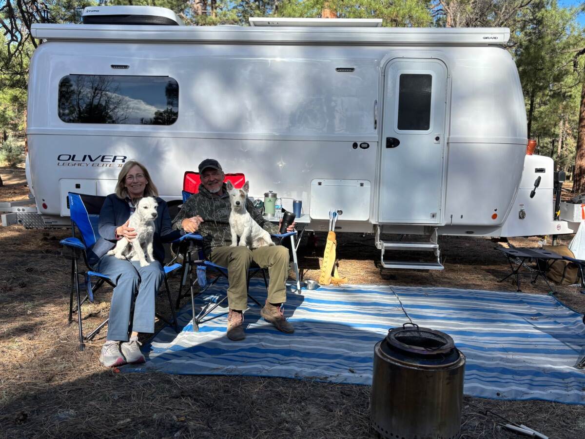
Greetings to you all! We are the happy new owners of Hull #1665, an Oliver Elite II. We picked up our new camper at the dealer in Colorado a few weeks ago. Our first night in the camper was at a Cracker Barrel on the drive home to New Mexico. Last weekend we had our first official 3 day -2 night camping trip and had a wonderful time. Our previous camper was a nuCamp Tab 400. We really loved that camper and it will be missed, but we both realized it was time to get a camper with more head room on the bed! (Especially Mary who always slept scrunched against the wall with two pups at her feet. :0) ) We live in Albuquerque and have been long time hikers, climbers, skiers, campers, hunters and general outdoor enthusiasts. Having a larger camper definitely makes traveling so much more comfortable. There is much about the camper that we love. We like the fact that the Ollie has a great suspension that will allow us to go on two track roads. The battery capacity and solar means that we can be off grid in NM for quite some time. After our first trip, we both realized just how comfortable and usable this camper really is. This summer we are planning a long trip back east for an archery competition and will be making a stop in Hohlenwald for some minor issues with the camper. We also are planning a long trip to Portland this fall to visit a new baby granddaughter. We look forward to meeting other Ollie owners on the road as we travel and at future Ollie rallies! Zane and Mary Rakes '26 Oliver Elite II One man, one woman, two small dogs and a sense of humor. 😊
 3 points
 -
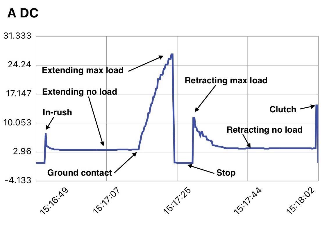
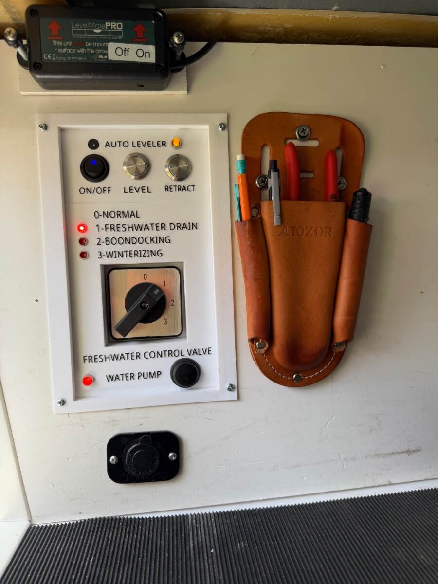
As far as I can tell, I’ve made the first automatic leveling system for the Oliver’s Barker stabilizing jacks! Maybe even the first 3-jack leveling system on a travel trailer! It’s simple to operate, safe, and works great! I built the leveling system as a novelty for my own entertainment, so I’m only posting it as a interest item not a recommended project. In reality, manually leveling with the electric jacks is already easy, particularly with a LevelMate, so automatic leveling isn’t really needed. There are even warnings that the jacks are stabilizers, not to be used for leveling. However, I believe the warnings are more about liability than capability, as long as the jacks are used within reasonable limits. I'd been thinking about an auto-leveling project for a long time, but was deterred by the thought of modifying the jacks with fiddly proximity sensors or revolution counters as used in conventional leveling systems. I didn't want to alter the jacks for a DIY project that might not even work. But then it dawned on me. The only time I really needed to know the position of the jacks, is when retracting them to their parked position. I wasn’t interested in returning the tongue jack to the truck hitch hight like some systems offer. So this led to a revelation that automatic leveling could be done with nothing more than current sensors mounted in a control box rather than on the jacks themselves. This was only possible because of the Barker jack’s mechanical clutch. When the jack reaches the end of its travel, the clutch activates with a distinct clack-clack sound. It was likely that clutch engagement would produce a unique current signature that could be used to detect when the jack is fully retracted. A plan was developing, but I needed actual amperage values for proof of concept. Fortunately I had a data logging ammeter, and the chart below illustrates the results for one of rear jacks starting from its fully retracted parked position. The jack was extended through free air until it touched ground and began picking up load, maxing out when the wheel lifted off the ground. Then it was retracted to the parked position until the clutch actuated: I didn’t include the tongue jack chart because it's far less dynamic — it's always under load, and the clutch doesn't normally actuate during leveling. The clutch only comes into play after trailer is hooked up to the TV and the tongue is manually retracted. The amperage results confirmed that current sensors could work, and beyond detecting the parked position, they could also be used to distinguish the different leveling phases: rear jack extension until firm ground contact for stabilizing, and then transition to "roll" leveling if needed. Completion of the rear jack phase could then trigger the tongue jack phase to handle "pitch" leveling. The amperage chart became the basis for the circuit and software design. No proximity sensors. No revolution counting. No permanent modifications — just two wires to each jack, a component box, and a control board. Sounds easy, but this was only just the start of a long process to perfect the system. I hope someone finds this interesting! Cheers! Geoff
3 points
-
@routlaw This link will take you to a post from @Raspy, who was the US distributor for McHITCH! It is the articulating hitch that Overland installed on his LE2. Mossey3 points
-
12 volt heat trace is about 3 watts per foot, and I'm not sure how you would calculate the length needed to protect the hot and cold loops. We picked up our trailer during a terrible ice storm with icicles hanging off the trailer while going down the road. There was real concern of freezing pipes. We said: Damn the warnings, we're running the gas furnace while going down the road!2 points
-
One other possibility is that if you fully drained your FWT for winterizing, the water pump may be sucking air because the siphon tube in the tank is not in water. This was an issue with the earlier Olivers (pre siphon tube) before they changed the design. Dave2 points
-
We use Brave for our browser and DuckDuckGo for our search engine.1 point
-
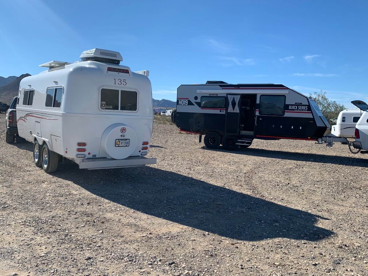
Perhaps some of you will find this rather long video on the MDC line of Australian off road campers interesting. The attention to and level of detail this company goes to is off the charts.1 point
-
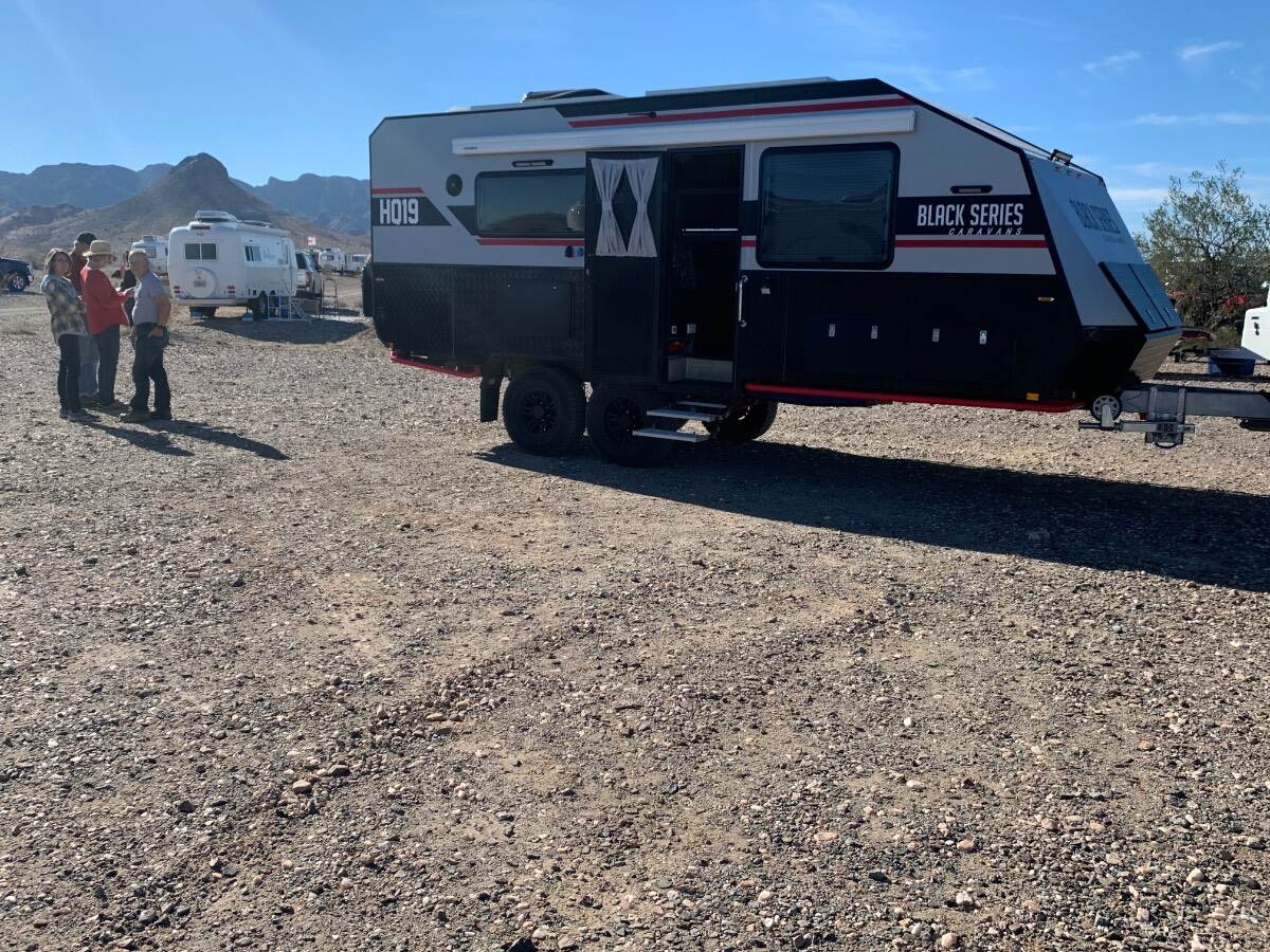
I have to admit the Black Series are not the most attractive campers out there but they do appear to be rugged. Thanks for the info.1 point
-
He initially went to a Black Series HQ19, we saw it at Quartzsite just after he got it. He’s since moved on to other Australian trailers. He hasn’t been on the forum in a while but does answer PM’s. Mike
1 point
-
Thanks @mossemi read through the entire post. I remember raspy from the early days of the forum and recall him going another route but did not know he was the Mchitch distributor. Watched an excellent video from one of the guys at ROA Off Road in Utah describing the various articulating hitches. The best one I've seen yet is a new one on the market, American made and engineered by the folks at Pause travel trailers that incorporate a ball hitch. Massive heavy duty thing too but see no way to use it on an Oliver without massive mods to the Oliver frame. I wish Oliver had gone the route of an articulating hitch and independent suspension.1 point
-
Looking forward to reading this interview. Thanks!1 point
-
Mike Sokol's Newsletter will be sharing his interview with Battleborn
1 point
-
Rob: Great for you! When I commercially air travel, I always go to the new scanners. I love watching the operator as he sees my replacement ankle, two replacement knees, and two replacement shoulders. Usually utters holy s h _ t and looks over to see who is grinning back to him/her. I often get asked what happened. I smile and say I sort of wore them out. Other than getting a great surgeon, it is all about the PT. Each joint has it's own protocols, and they DO NOT transfer to other joints. For knees, the PT is can to can't deal. Under supervision, you can work them at your MAX tolerable effort to exhaustion. Do it every time and keep improving that up-slope curve and the "Bean Counters" will keep you getting better. For the knees ten weeks after surgery I was with my wife a Snowbird UT. First run I was being passed by all the first graders. Each run I got faster... first 6th graders, then some high schoolers. After four runs I was feeling 75% of what I was many years before. After run 5, I was feeling stoked and asked my wife if she wanted to bet a pitcher of beer for the winner to the club house. Her response was sure, but I want a 30 second head start. She bought the beer. Point is do the PT and do the PT homework to the max your PT team will allow. Tell them your goal is the knees of a 29-year-old. Then do the work to get them. Now at 74, I can outwork anybody I know even close to my age. I'm still flying paragliders, swimming three miles a week, doing weight training, and of course sure surf kayaking. Aim high! GJ1 point
-
Two total knees, 2019 and 2020. I, too, have lumbar scoliosis. Full recovery for each knee took 6 months+, but the recovery was truly full. Once you can tolerate it, cycling is a big help to full recovery from knee replacement. I eventually recovered full range of motion. I need knee pads when kneeling on hard surfaces, but once I was fully recovered, I could kneel without pain. My 2 total knee replacements impose no limitations on use, or maintenance of, our 2022 Elite II. Keep at it!1 point
-
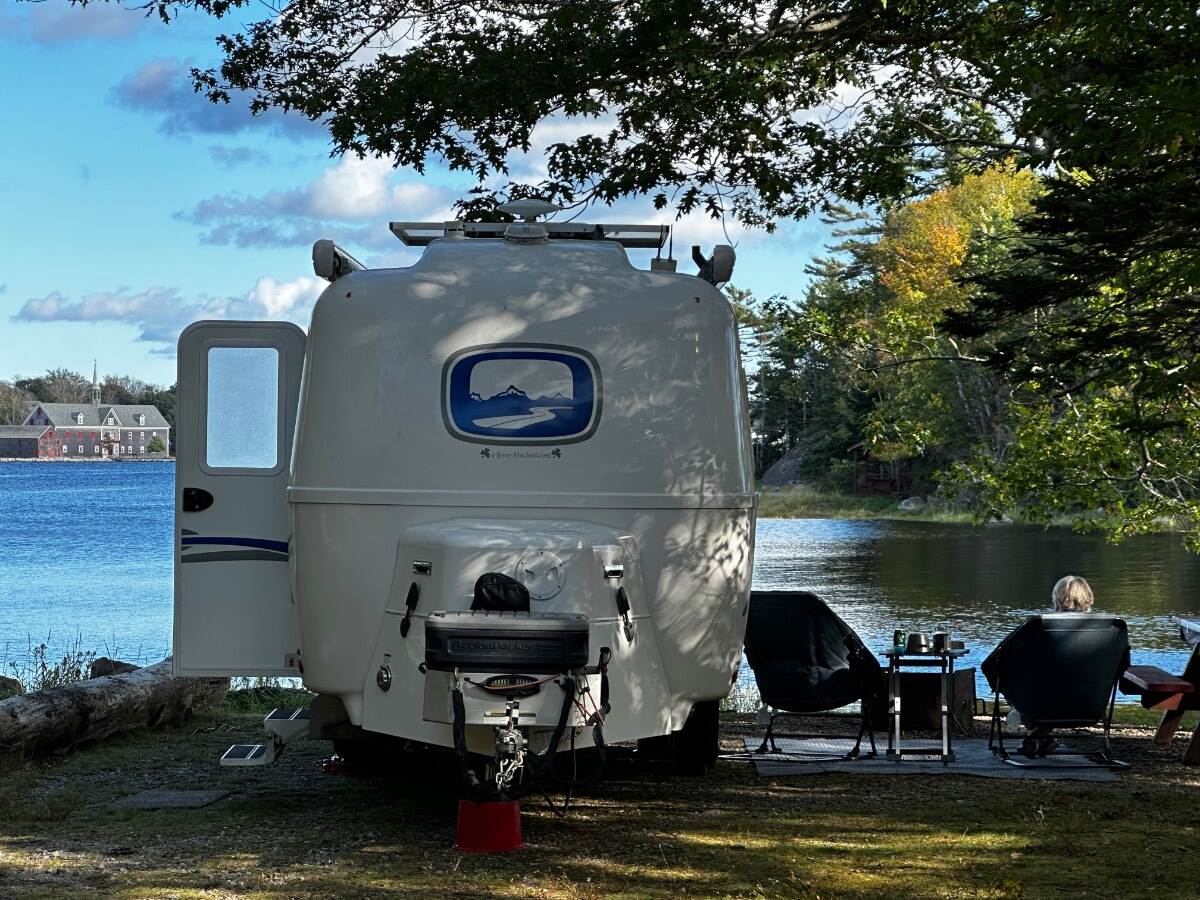
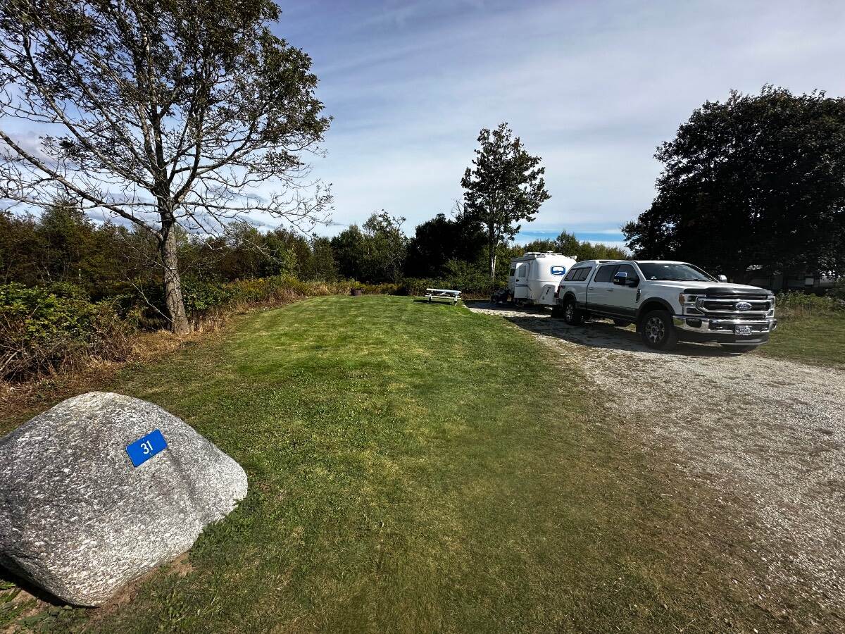
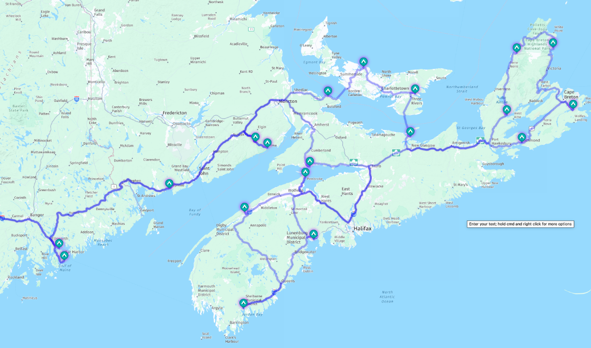
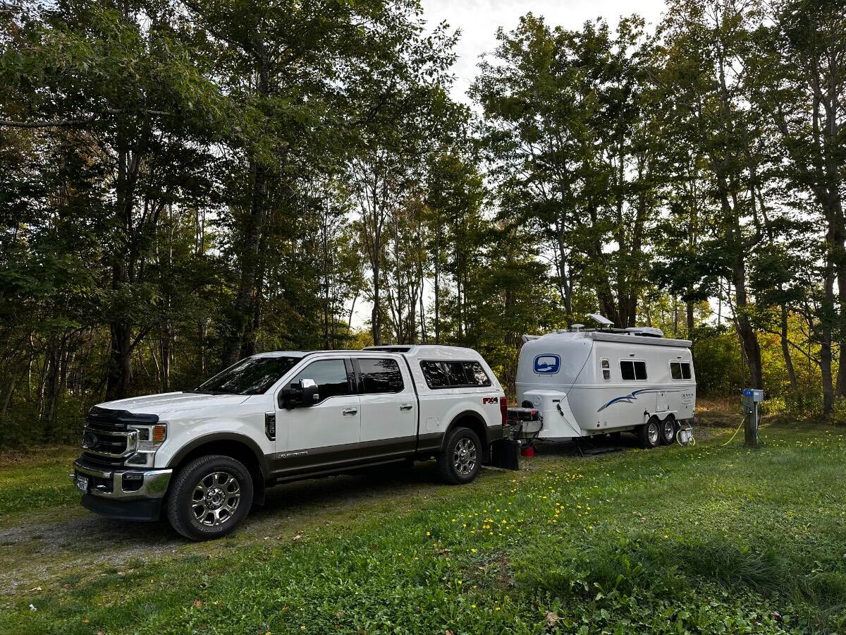
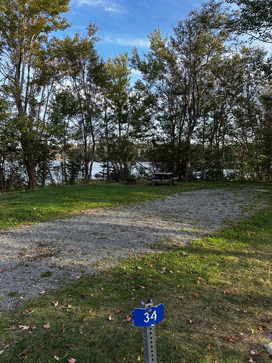
We did a full month long trip in Sept thru early October to the area shown 2 years ago and it was barely long enough. Each of the items with a TENT on the map are highlighted in our trip..."the big loop" and and be seen in pictures with comments here: Scroll down to the pix section on Nova Scotia Main Island. https://4-ever-hitched.com/the-big-loop-2024 Graves Island Provincial Park - Site 31 Shown - is Just South of Halifax on the main island. Puts you perfectly in a spot for the UNESCO site of Lunenburg, Halifax and Peggys Cove as day trips. I would stay there at least 4-5 days if I were doing over. To get into the park you cross a causeway into the park which is on an island. Going south don't miss staying at "The Islands PP" Further SE = Site 54 - Islands Provincial Park - Puts you on the edge of the water....this is on the SE Corner of the main Island. North on the main Island before you cross onto Breton Island you may want to also see the Fortress of Louisburg...which is on the north east side of the island. A good stop point is Mira River Provincial Park as you can easily drive down to Fortress Louisburg from Mira River...and then north after that stop. SIte 28 - Electric & Water at Mira River PP Above....but the site 34 below would fit and is right on the bay, but no Electric or Water... I've labeled all the campsite photos for each park in our blog, but If you have any specific questions we could get on a call. Craig & Rose
1 point
-
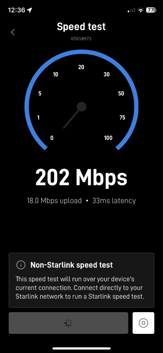
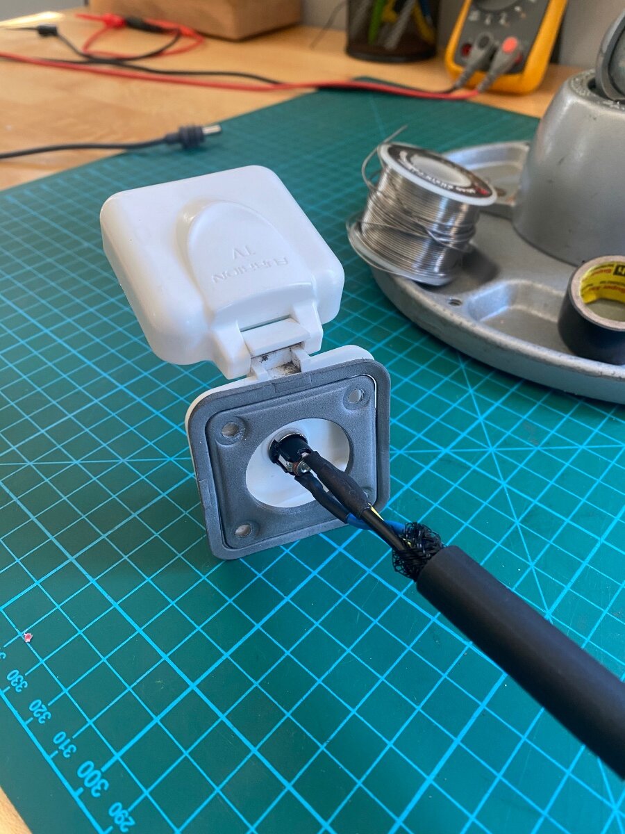
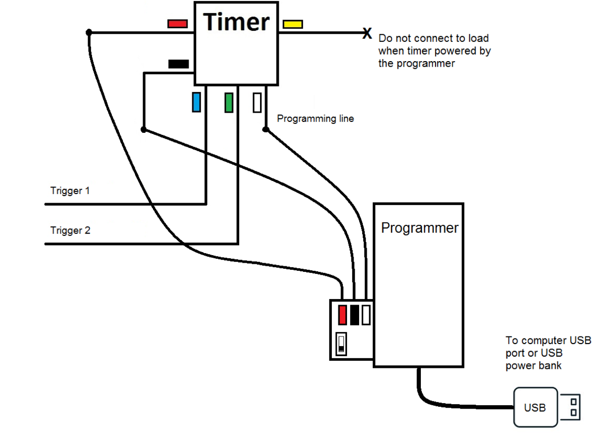
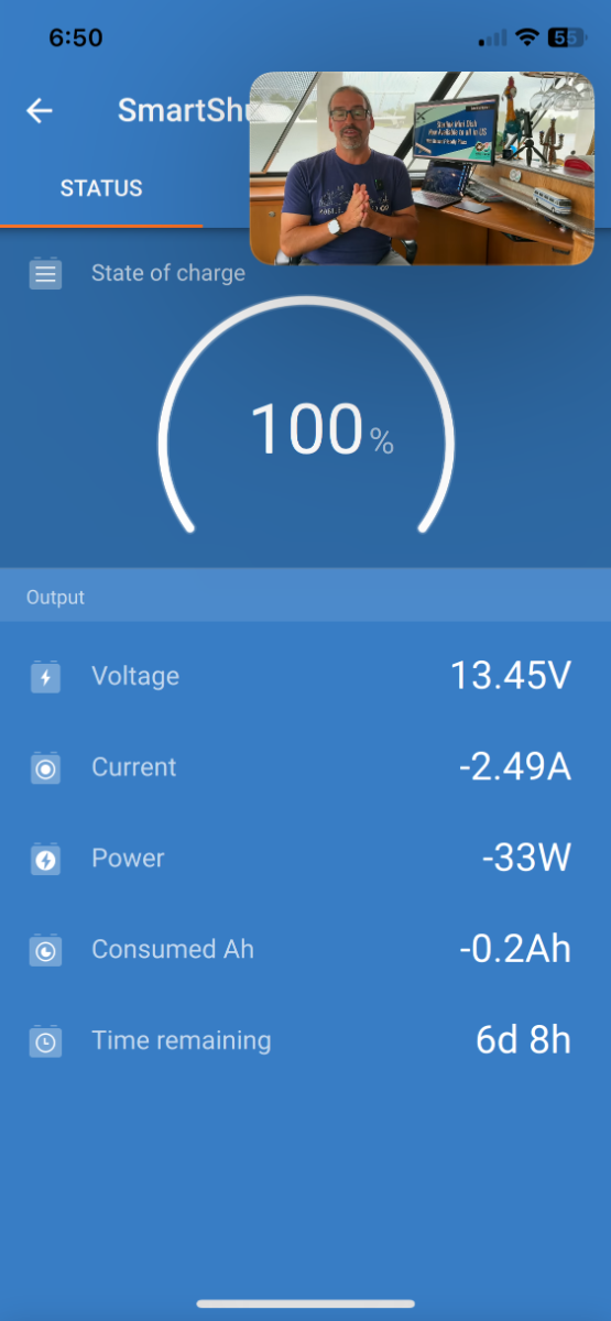
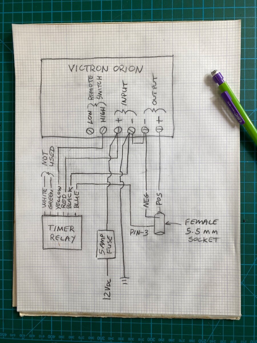
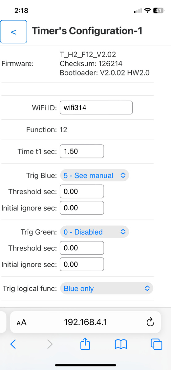
After lugging around my old heavy Gen-1 Starlink for a few years, I was thrilled to get the new Starlink Mini. It’s small and light, and the router is built into the dishy. It speed tested at 202 Mbps, a very respectable speed, although not as fast as the Gen-3 which typically runs over 300 Mbps. The Mini comes with a 50’ x ~1/8” diameter power cord that has 5.5 mm barrel connectors on each end. It also comes with a 120 volt AC wall transformer that puts out 30 volts dc (vdc.) The Mini is rated to run on 12 to 48 volts vdc, and 25 to 40 watts. It peaks at 60 watts with snow melt on. The 12 Vdc rating is an attractive feature, particularly for Boondockers who don’t have inverters. However, when I first hooked it up to the Oliver’s 12 Vdc battery… it would’t work?? After some investigation, it turns out that it’s not so simple and I’ll try to explain why: Given that the AC transformer puts out 30 volts, and the power is about 40 watts, then it would be drawing 1.3 amps per Ohms law (40w/30v = 1.3 amps.) With the same calculation at 12 volts, the amperage increases to 3.3 amps. The resistance of the long thin power cord can’t handle this higher amperage and the resulting voltage drop puts it below the minimum 12 volts operating range. In fact, I did some bench testing and found it would only work at voltages over 18 volts. There are solutions to this issue including cutting the cable shorter, using a larger gauge cable, or increasing the voltage. Without a better option, I chose to increase the voltage. I looked at cheapie power converters that would probably work, but I wanted something more robust and higher quality. I found a Victron Orion TR 12/24-5, isolated, DC to DC Converter, and it was perfect for the job. It has a 12 Vdc (+/-) input and an adjustable output of 20 to 30 Vdc at 5 amps. Standby power is under 80 mA, and it has remote on/off switching capability. It comes factory set at 24 Vdc, but I adjusted it to 30 Vdc output with the potentiometer on the front. To connect the Mini to the trailer’s 12 Vdc power system, I installed a 5.5 mm female panel mount socket into the Satellite TV inlet. I removed the Coax connector and the 5.5 mm socket and nut fits perfectly in it’s place. Oliver conveniently labeled it “Satellite.” If you need the satellite TV, then install a third “Furrion” inlet as I did for my old starlink RJ45 connector. I mounted the Victron under the rear seat on the street side. The socket wiring was sheathed and routed along the ceiling of the outside storage garage. There are a number of options to pick-up 12 volts in that area, I took power off one of the circuit breakers. I ran the negative wire to the ground bus under the rear dinette seat. The Mini comes with both a snap-in kick-stand and a 2” pole mount, and they’re both necessary for optimum RV use. I prefer having it on a pole, but we often have to move the dishy away from the trailer for a clear sky view. That’s why it’s a bad idea to shorten the cord. It also has an RJ45 port that I suppose is for hardwiring without WIFI, but I probably won’t ever use that feature. I built-up some PVC fittings on my 10’ Electrical Metallic Tubing (EMT) mast to fit the Mini’s pole adapter. (See the post for Tacky Starlink Dishy Mast). A little sanding was involved, and the starlink mount uses a thumb screw to hold it in place. It’s better to turn the Victron off when not in use, so I recommend using the remote switching feature with a switch installed in an easily accessible location. I’m too forgetful to switch the Victron off every time, so I came up with a way to turn it on & off when the Mini’s power cord is plugged in & out. Read on if your interested in that part of the installation: The “three pin” 5.5 mm female socket sold by Amazon has a built-in switch that’s designed for appliances that use either batteries or a 120v transformer supply. When the transformer is plugged in, the pin-3 switch opens to disconnect the batteries. This is opposite of what’s needed for the Victron remote switch, but it can be used to trigger a digital relay and it’s actually easier than it sounds. Amazon carries fun little programable 5 &10 amp timer/relays for under $20. I already had the 10 amp version in the Oliver for a hot water recirculation pump timer, and it works great! The 5 amp is adequate for this application, and you will also need the $20 dollar re-usable Bluetooth programer. They use 50 μA of idle current, which is nothing, and they can be programed for delay-on, delay-off, flashers, dimmers, duck decoys, and more. But for our application, we’re just interested in the trigger functions, specifically the “ground-open” trigger. Before installation, the relay has to be programed from a smart phone or computer. It’ links by WiFi to flash the program into the relays memory. Use wire nuts to connect the timer and programer together, and power them from a USB port. Follow the well written and simple programing instructions using the settings shown in the screenshot below. The relay requires a timing function, so I arbitrarily used function #12, which is “delay-on.” I set it randomly to 1.5 seconds. The trigger is programed to use the “Trig Blue” set at #5, which corresponds to the blue wire used as a “grounded trigger.” The green wire trigger is disabled. My wiring sketch shows that the timer is powered with 12 volts from the Victron’s positive and negative inputs. The relay’s yellow output wire feeds the positive side of the Victron’s remote switch (the negative side is not connected). The Victron’s output feeds the 5.5 mm power socket, and the blue trigger wire goes to the 5.5mm socket’s pin-3. Use a continuity tester to identify pin-3, it’s normally shorted to the negative lead of the socket and it “opens” when the male connecter is plugged in. The socket barrel is negative, or ground, and the center pin is positive 12 vdc. There is one other step to make this work. This Victron model is “Isolated,” meaning that the input and output “negative” terminals are isolated from each other. It needs to be “non-isolated” because the timer is grounded to the Victron input, and the socket is grounded to the output, and the trigger needs continuity between the two. So remove the jumper wire that comes on the Victron’s remote switch, and use it to jump across the two negative terminals. Victron support confirmed that shorting the grounds is not a problem, it just un-isolates it. This works satisfyingly well! I checked out the power draw with the solar turned off, and while streaming a video. It was 2 amps, 27 watts (after subtracting the parasite load). That’s a huge improvement over my previous Starlink, and I don’t have to worry about running the inverter and draining down the batteries anymore. I hope someone finds this useful Cheers! Geoff
1 point
-
🎉 Introducing: Oliversary Stories! We've just added a brand-new section to the forum, and we couldn't be more excited to share it with you. Oliversary Stories is a dedicated space for celebrating the adventures of Oliver owners — real journeys, favorite destinations, and the memories that make life on the road so special. Whether it's a cross-country haul, a hidden gem campsite, or a trip that changed everything, these are the stories that remind us why we love this community. Here's how it works: our team will reach out to owners to gather highlights and share them here, so every story you read comes straight from someone in the Oliver family. This forum has always been built on the experiences of real owners, and Oliversary Stories is our way of putting those experiences front and center. We can't wait to start sharing — and we have a feeling you'll find plenty of inspiration for your next adventure. Interested in sharing your story? We'd love to hear from you! Reach out to us at media@olivertraveltrailers.com and let's make your adventure part of the Oliver family story. Stay tuned. More stories are coming. 🛖✨ https://olivertraveltrailers.com/forums/37-oliversary-stories/1 point
-
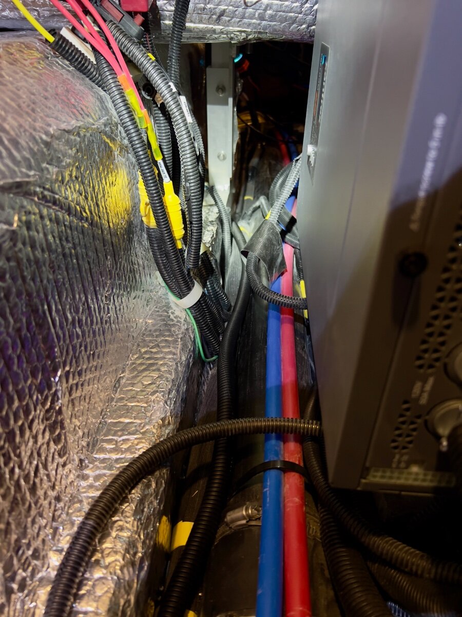
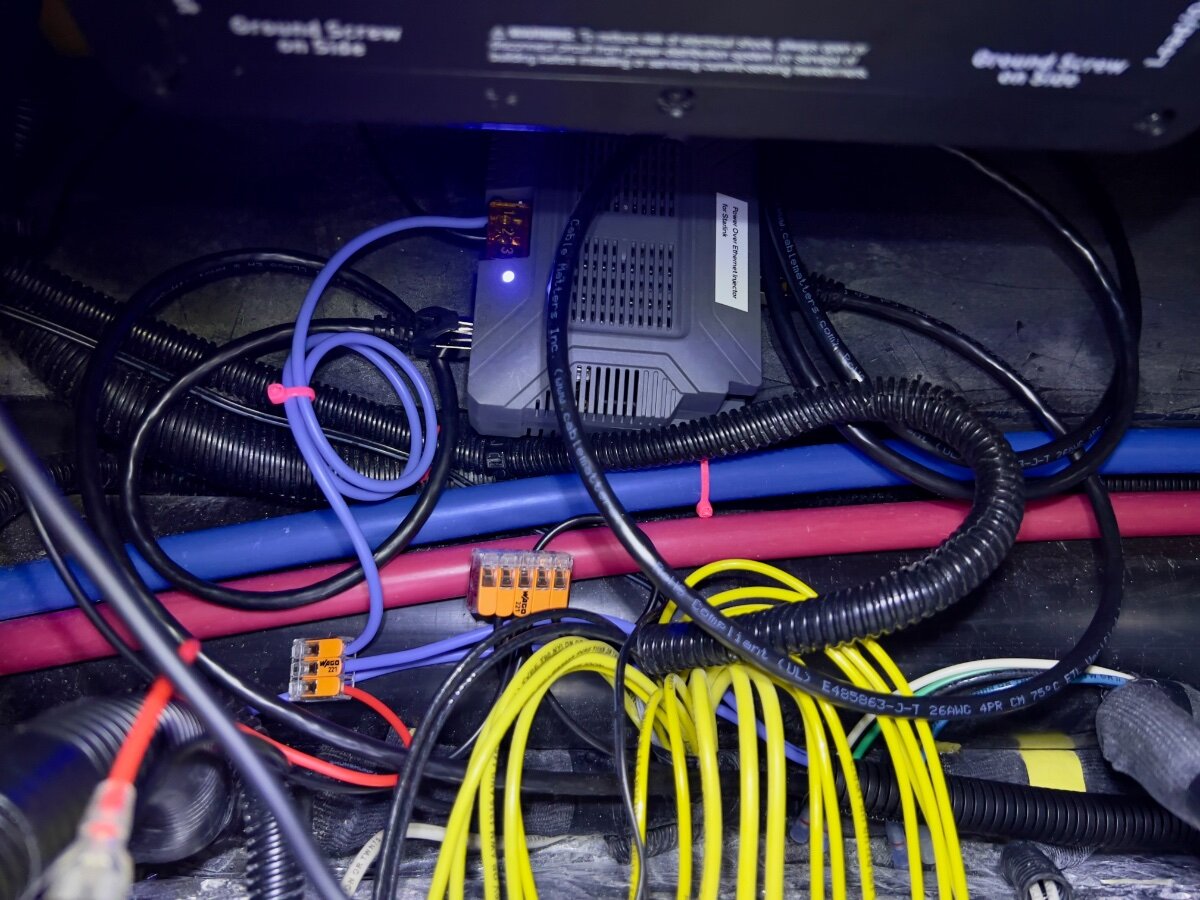
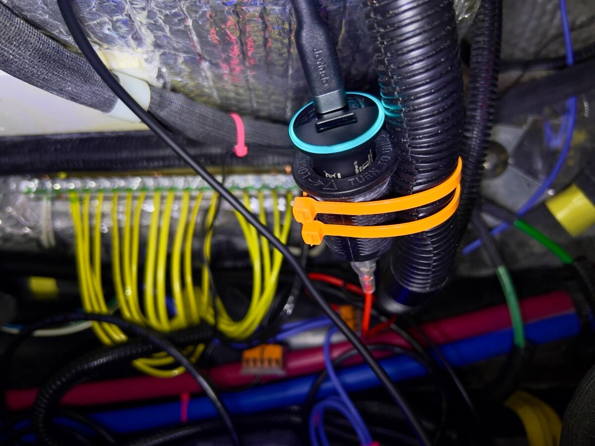
On a recent trip from Dallas to South Carolina we stayed in multiple locations with no (or very limited) communications capabilities (cell phone or WiFi). Over the three years we have owned our LEII, there have been many other occasions with no ability to communicate. As a result, we decided to order a Starlink Mini and a Starlink Router Mini to use on our trailer trips. I have been following Starlink related postings on the OTT Owners Forum, especially since the release of the Starlink Mini. I have found the postings by @Snackchaser particularly helpful in planning the installation of our Starlink system. I especially liked the use of a Power over Ethernet (PoE) injector to power the Starlink Mini and to provide an Ethernet connection from the built-in router back to the trailer, using a single cable. Installing the PoE injector and a DC powered router in the attic of the LEII seemed a reasonable location, being nearly directly above the exterior Furrion ports for connecting satellite and cable TV. So I planned to install in a similar location in the attic of our LEII, assembling a list of the components required. I ordered a PoE injector from MobileMustHave.com and the rest from Amazon. Once all the key components had been delivered, I began the installation, with the first step being to replace the Furrion Satellite coax port with an RJ45 pass-through connector and to fish an Ethernet cable from the basement to the attic. Replacing the Furrion coax connector with the RJ45 pass-through connector was no problem, even though enlarging the hole through fiberglass exterior shell was required. However, fishing an Ethernet cable from the basement to the attic proved to be a major obstacle. Although I have prior experience fishing wires through difficult spaces, I was unsuccessful getting a fish tape (or rods) from the attic to the basement. I could get the end of the fish tape rods down near the ceiling of the basement, where the interior shell ends and multiple cables run up to the attic area at the rear of the trailer, but not into the basement. As suggested, I tried following the A/C drain line and multiple other locations but could not get past the bottom of the inner shell into the basement. I tried running the fish tape/rods in both directions. No luck. Consequently, I began to ponder other installation locations inside the trailer for the PoE injector and Starlink Router Mini. After a couple of days, I had an Aha! moment- install the PoE Injector and Router Mini under the rear dinette seat. I inspected the space between the basement and the rear dinette seat, nearly all of which is readily accessible from the two rear street side hatches and the rear dinette seat hatch. Only the space under the battery compartment is not accessible from directly above, but is easily accessed from either side. I looked for any obstacles to using this location and found none. I could easily route the Ethernet cable from the Furrion/RJ45 pass-through connector forward to beneath the rear dinette seat. I located the PoE Injector atop the trailer frame member, just below the Progressive surge protector box, which is mounted on the aisle wall of the rear dinette seat. The PoE jack and the power terminals of the PoE Injector are positioned toward the front of the trailer. I connected a 20 foot shielded Cat 6 cable from the inner side of the Furrion/ RJ45 port, then routed it under the floor of the basement, around the street side rear stabilizer, then following the waste water line, forward to the area under the rear dinette hatch. About 3 feet of excess cable are coiled in the basement, concealed by the rear wall of the basement. I installed a lighted rocker switch through the forward basement wall, mounted high, almost directly above the side-to-side bubble level on the left side of the basement entry. This switch is to control 12VDC power to the PoE Injector and the Starlink Router Mini. Using 14 AWG silicone coated wire, I ran two purple colored wires from the space beneath the rear dinette hatch back to the rocker switch on the forward basement wall. A third, 14 AWG black wire was also run along the same route to the rocker switch. The switch has two terminals with red lead wires,: one to the DC power source and one to the load. The third terminal has a black wire, which connects to ground (the bus bar). The ground wire enables the light on the switch to operate when DC power is ON. On the DC power panel, position 15, I installed a 15 amp fuse. One of the purple wires connects to the 12VDC positive terminal on the PoE Injector. The other purple wire connects to position 15 on the rear of the DC power panel, using a crimp on connector. The single black wire from the switch connects to the ground bus located under the rear dinette seat. Another 14 AWG wire connects the PoE Injector negative terminal with the other end connecting to the bus bar. All wire-to-wire connections were made using Wago lever lock connectors. I also added a 12VDC auxiliary power outlet (cigarette lighter type) which is connected to the same circuit as that which powers the PoE Injector. An Anker 323 USB-C Car Charger Adapter (USB Power Delivery (PD) capable) plugs into the auxiliary power outlet. A USB-C to Male to DC 3.5 x 1.35mm Male Power Jack is used to power the Starlink Router Mini from the Anker charger. I found the Starlink Router Mini conveniently fits on top of the Progressive Surge Protector box. I later secured it with a releasable zip tie around the surge protector. The 20 foot Cat 6 Ethernet cable from the rear connects to the PoE jack of the PoE Injector. A 5 foot Cat 6 Ethernet cable connects to the LAN jack of the PoE Injector and to the WAN/Satellite port of the Starlink Router Mini. All Cat 6 Ethernet cables used are shielded. I believe this installation location approach has several advantages over an attic installation: Access is MUCH easier. Fishing wires is no challenge. A dedicated circuit from the DC power panel provides power to all Starlink related components. A lighted switch for the PoE Injector and Starlink Router Mini is located in the basement, near the exterior pass-through Ethernet jack. The PoE Injector is located where it cannot be covered by clothing or other cargo stored in the attic which might cause overheating. The VERY bright blue light on the PoE Injector is not visible in the cabin (always ON if power to the PoE Injector is ON). The Starlink Router Mini is located centrally in the trailer and should provide uniform WiFi coverage within the trailer. We have not yet taken the Starlink on a shakedown trip, but plan to do so at the end of August. Regards, Don
1 point
-
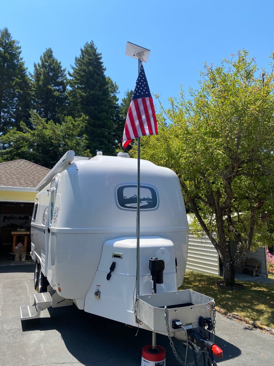
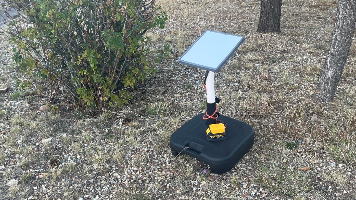
Given this is our main mount, nicely sitting in our truck bed, I was thinking of a moveable stand for the occasions where the truck cannot be parked clear of trees! Meanwhile, my son broke the base to a fan he uses often in his apartment. After removing the broken base, I thought, "a patio umbrella stand would work nicely." So why not use an umbrella stand for the Starlink Mini dish? The kind you fill with water would be convenient, since when empty it weighs less than a pound (we always carry 35 gallons extra water on the TV). It works great and can be placed anywhere! I purchased this model from Lowes, since it is rectangular (most are round) and it has a nice handle. https://www.lowes.com/pd/Patio-Premier-Patio-Premier-Square-Blow-Mold-Umbrella-Base-Black/1002629278 You can configure all the fancy poles and mounts you want and I'm done with $50 total in parts ($10 for PVC parts) which will work anywhere without cables. 😎
1 point
-
Here are the program settings for the relay:
1 point
-
To Oliver Owners and Valued Customers, As committed to several weeks ago, the Oliver Travel Trailers business owners and leadership team have discussed at length internally, with our dealer partners, as well as with Oliver owners and potential customers, the subject of continuing to offer service here in Hohenwald, TN. Oliver Travel Trailers has decided to leave our service facility fully operational for the foreseeable future. Oliver Travel Trailers remains committed to supporting and training our dealer network to provide exceptional opportunities to purchase and get an Oliver serviced as close to home as possible. The Oliver sales and service team remains available to assist with any needs or questions that you may have. Once again, Oliver Travel Trailers truly values the relationships we have with our owners, potential customers, and business partners. Thank you for the feedback and continued support. I look forward to seeing many of you at the Oliver Owner’s Rally in May. Best, Rodney Lomax Director of Operations Oliver Travel Trailers Sales & Service1 point


.jpeg.799f3cf194b3b21d05b2a7bb19f728b1.jpeg)
.jpeg.dd379fc2e5087fa6910ce21b437441ad.jpeg)
forPoEInjector.jpeg.2ff4c7b3725adaf25e5bdfc30965ceff.jpeg)
atopProgressiveSurgeProtector.jpeg.5c03a313182d5fdb47bf1a254dec329d.jpeg)


-
Recent Achievements
-
")


")


")


