mossemi
-
Posts
1,803 -
Joined
-
Last visited
-
Days Won
43
Everything posted by mossemi
-
A different Sirocco fan mounting option. Mossey

-

Gorilla compact 25’ hose for marine and RV use
mossemi replied to Patriot's topic in Mechanical & Technical Tips
I will be the first to admit that I lean toward the lazy side of the street! This is my method for storing the Gorilla Marine and RV hose. Mossey
-
New Epoch 300AH Essential Battery, all going well except…
mossemi replied to routlaw's topic in Mechanical & Technical Tips
I had forgotten about Bill's Lithium installation and the issue he found with his shunt. When you are investigating your battery cable’s, be sure that every negative wire or cable is on the correct or load side of the shunt. There should only be a single negative wire or cable attached to the negative battery post. When wired correctly, the shunt will have the ability to read all 12V usage. Does the Epoch battery have an app the you are reading the SOC with or are you reading the Blue Sky remote? Mossey -
New Epoch 300AH Essential Battery, all going well except…
mossemi replied to routlaw's topic in Mechanical & Technical Tips
For the sake of calculations, I believe the Blue Sky Solar Controller 3024iL is a MPPT type solar charge controller. Since this is the first time charging the battery for this installation, Rolind's comment about the SOC and the BMS is correct. The SOC is a calculated value and drift is a common occurrence. Mossey -
Hope they help! Mossey
-
This schematic and information is from Barker's website and may be of help! Mossey vip_3000_all_pages.pdf
-
Water pump not working -- problem solved -- FYI
mossemi replied to ZLarryb's topic in Mechanical & Technical Tips
ZLarryb, the plastic connector/tee fitting nut is the red notation. the black plastic tie-down is the yellow notation. the green arrow is pointing to the green "witness marks". Witness marks are sometimes used to mark a 2 part connection like a nut and bolt or in this case it marks both sides of the water pipe connection. It is marked during installation on both sides of the connection and it is a quick visual confirmation of a connector being in the original position or not. Due to the angle of your picture, I can’t verify its position because I can’t see both side of the mark, but you can do a quick verification. Mossey
-
I believe Oliver's only have 1/2" PEX, but I’m not assuming anything. I only carry 1/2" spare parts and pipe. I carry a SharkBite 90*, coupling, tee, cap. I also carry a PEX pipe cutter and a SharkBite fitting removal tool. A word of caution about SharkBite fittings in general, some of their fittings are reusable and others are single use, so pay attention to which you purchase. Although I have complete confidence in SharkBite fittings, I have never had one fail while in service. I have had installation failures of my own making. So read all documentation available and follow the methods outlined within and all should be good. I do have PEX crimp rings and crimpers at home and they are very hard to use for repairs below decks. So I don’t have any problem leaving SharkBite fittings in service, that I installed in an emergency. The last bit of advice that I have is, buy a reusable SharkBite PEX fitting and some PEX pipe and get busy practicing. Mossey
-
Welcome! It looks like your Ollie is right where it belongs, is use and camping! Welcome
-
Andersen WD Hitch Periodic Maintenance?
mossemi replied to Galileo's topic in Mechanical & Technical Tips
I hope he is OK! Mossey -
Andersen WD Hitch Periodic Maintenance?
mossemi replied to Galileo's topic in Mechanical & Technical Tips
You should have headed west and rode around Starved Rock SP. It still has a bunch of twisty 2 laner's. Mossey -
Andersen WD Hitch Periodic Maintenance?
mossemi replied to Galileo's topic in Mechanical & Technical Tips
I also got started in the stereo installation business, but with 4 track tape players. It was also an after school job. That experience led to a cell phone installation job 20 years later with General Telephone. That job led to 30 years in the cellular phone business. When I retired in 2017, I found immediate employment at home and the list keeps on growing. The really good part is that I get to pick the next job! Mossey -
Our standard practice has always been to turn the Truma on at the inside control panel when we needed hot water and then turn it off when not needed. This is not a solution to the problem, it just reduces the likelihood of a fire 🔥 when we are not around. We will also add a step to our departure and setup checklist , to turn the outside switch off or on as needed before travel! It’s the best we can do until a repair has been completed. Mossey
-
Truma Aqua Go randomly comes on with CP off
mossemi replied to Steve Morris's topic in General Discussion
I haven't seen or heard of this before. The ECO mode does fire up periodically as needed to keep the water warm. When you mention 'control panel', are you referring to the inside panel? My inside control panel is above the curbside bed and the wiring is accessible from the porthole in the cabinet above the cooktop. Mossey -
@MAX Burner, Maybe it’s time to try making espresso shots with your favorite Black Rifle coffee and really make that half-cup of Joe work a little harder. Mossey
-
I know I’m a little late to this party, but this search format always works for me. Just change the verbiage between the 'single quotes'. site:olivertraveltrailers.com 'oliver owners rally' Mossey
-
Steve and Deb Try to Stay Warm - January 15 - February ?
mossemi replied to Steve Morris's topic in General Discussion
@Steve Morris On behalf of all Floridian's, I will say "we do all we can to make our visiting Snowbirds feel right at home". Mossey -
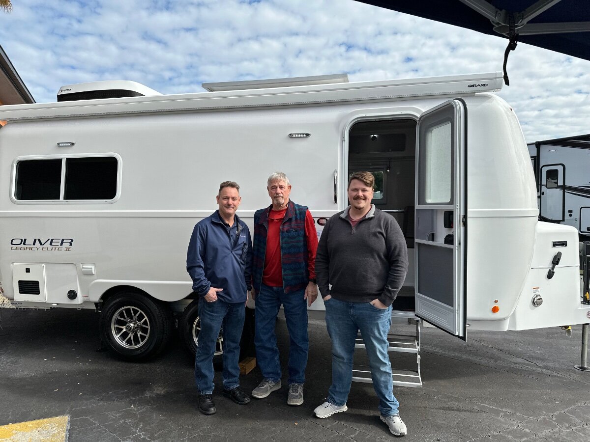
Visiting Scott and John Oliver in Tampa,FL. They are in town for Oliver TT demo days at Lazydays RV. Lazydays has 3 locations in Florida with Ollie's in stock for your viewing pleasure. Mossey
-
Truma Pressure Relief Valve Leaking
mossemi replied to Rich and Jane Walker's topic in Mechanical & Technical Tips
Also use the pressure regulator on the fresh water fill inlet. Although there are fewer restrictions on the fresh water fill plumbing, it’s still a good practice. This would also apply when you start using the filter. Mossey -
Truma Pressure Relief Valve Leaking
mossemi replied to Rich and Jane Walker's topic in Mechanical & Technical Tips
I learned something new, thanks! Mossey -
Replacing black water release valve
mossemi replied to Imelda's topic in Mechanical & Technical Tips
A couple more steps that I would add to @jd1923 suggestions is to make sure that both the black and grey blade valves are closing completely. Both black and grey tanks empty out of the same pipe at the rear bumper, so either blade valve may be leaking. Try pushing down on both blades to check for any movement which could indicate the need for a cable adjustment. And if you haven’t previously lubricated the valve cables, it will help valve opening and closing. It goes without saying that troubleshooting the sewer system it much easier to do at a full hookup site. Mossey -
Congratulations and welcome! From the looks of your first picture, it looks like you may already be in Mayport! The cabbage palms, sunshine, blue skies and the Atlantic Ocean in the background lead me to think you made the trip south successfully, congratulations. Mossey
-
Call Blue Sky technical support, as other BS owners have reported that their support is excellent. Mossey
-
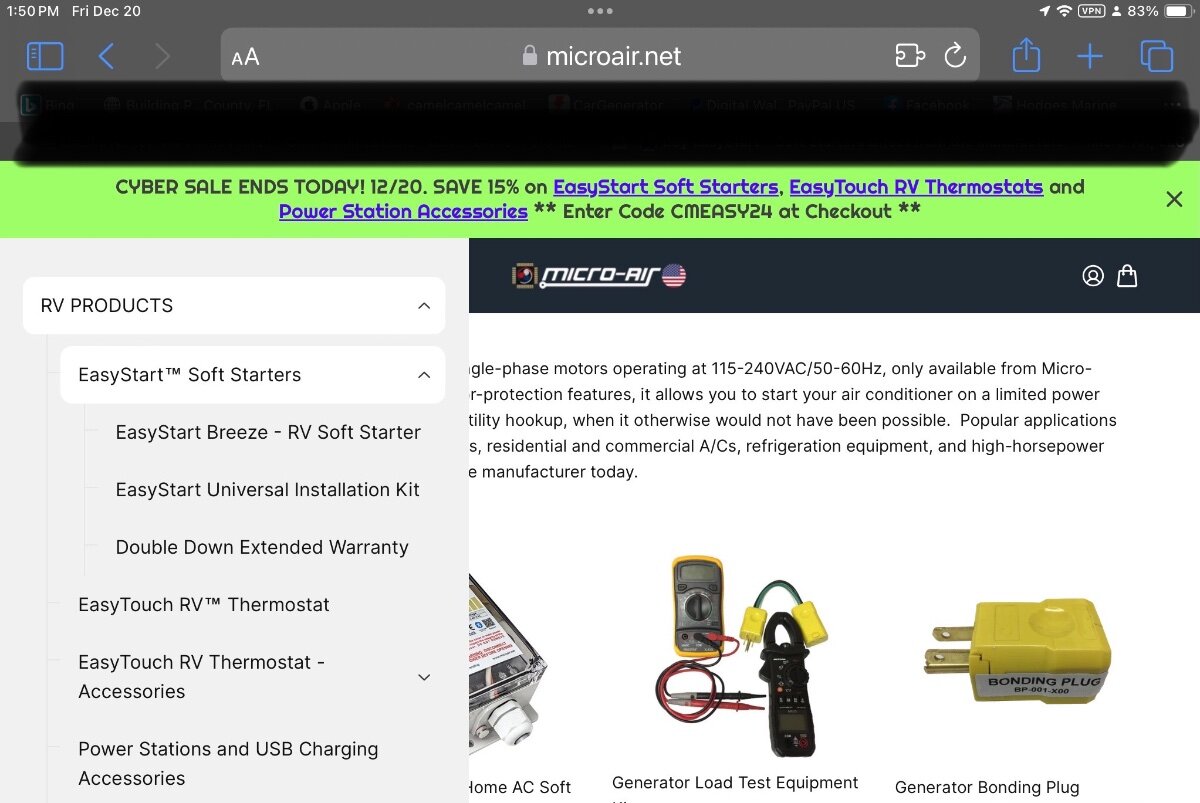
I have found Micro-Air support to be very helpful. Mossey
-
I didn’t think you went to bed that early! Mossey