Leaderboard


Popular Content
Showing content with the highest reputation on 12/14/2025 in Posts
-
In my eyes, John Davies was a pioneer in DIY efforts. I have often referred back to his wisdom and approach when doing my own. Sadly I have neither the tools, equipment or skills as this great craftsman. But I sure can gain insights on how to do things in our trailers from his efforts. Attached is a list I "Borrowed" from his posts. Saving a copy as a MS Word document lets me easily search his DIY Library. I hope it is useful to you. When you do, say a thanks to John D. It would be good Kama! Geronimo John John Davies Posts Index (April 2023 Version).docx5 points
-
The NTSB (National Transportation Safety Board) investigates transportation accidents to find causes and makes safety recommendations, while the NHTSA (National Highway Traffic Safety Administration) sets and enforces vehicle safety standards, conducts recalls, and creates regulations, essentially acting as the rule-maker and enforcer to the NTSB's investigator/advisor role, though both focus on U.S. transportation safety. NTSB looks backward at incidents (planes, trains, cars) to prevent future ones, whereas NHTSA looks forward, setting rules for cars on the road today, including new tech like automated driving systems (ADS).5 points
-
Monument Vally We are camped in the only open campground in Mounment Valley and there are only two other rigs tonight. We are lucking out with amazing weather and empty parks. Tonight's sunset. I generally avoid shooting classic images that have been shot by 10,000 phtotogrphers that are better than me. These are so classic, I wanted the images.,.. enjoy
 5 points
 -
And that Krea was the percise point of my above "Let's Ponder" post. Well said. For most of us with three BB's and a 300 Amp Fuse, we likely will not have a problem. The following uses some WAG's such as inverter efficiency (75%) and disscharge voltage of 12.5V. Both of which are just numbers are WAGS. But for illistration the following provides a basis for "Pondering Further" for a single 100 AH BB install: A 2,000 watt inverter overloaded could draw for a moment at least: (2000W / .75 ) /12.5V = 211 amps. . A 3,000 watt inverter overloaded could draw for a moment at least: (3000W / .75 ) / 12/5 = 320 amps. Neither likely would blow the 300 amp fuse. But over time, repleated again and again, then it is more than just possible that the BB design would become a problem for such installations. Yes we all could blow holes in the above "Hypothetical" example. But the underlying concept likely explains why some installs out there are having problems. Dragon Fly likely will be redesigning their B+ terminals as is obvious. But do I see a voluntary recall in the cards. Not likely, as it could bankrupt their company. As such it will likely be necessary for a federal recall to be demanded for the installed fleet. On the other hand, is it possible for Dragon Fly to redesign the B+ termina? Sure. They may even come up with a voluntary recall process to update those terminals for free, but likely we will be eating the shipping costs. But in the meantime to stick us with fees and charges, not to mention shipping costs to verify they have a known problem is a bad business decision. Think Ford: Cam Phaser Mess approach: Deny, Stall, Think Toyota: Cam shaft approach: Admit, Apologize and Fix IT, GJ3 points
-
Another thing that is most likely the cause for a hot battery lug and has not been mentioned yet……a loose connection to the outside world. Installer error. It’s easy to get a loose connection. We should check all of the 12 volt connections periodically, especially the high amperage ones. When I first installed my lithium batteries and put them under a heavy load I checked all of the welding cable crimped on lugs. Only one factory crimp got hot so I removed it and crimped it again. I have not had a problem with any of the connections getting warm under heavy loads since. Yet something else we need to check, oh goody!3 points
-
We installed two BB 100ah batteries in January, 2021. Later that year I added a third battery when they went on sale. I’ve had no issues. Terminals are tight, no wobble like what Will is testing in the video. It’s within about a month of when I got my Ram 2500 and it now shows about 58,000 towing miles. Mike2 points
-
Chris, great question. This is what I came up with in a quick open source search. I thought it was worthy of posting here with regard to Li bats. I did some limited work with the CPS folks in my former career mostly on imported consumption products. https://www.compliancegate.com/lithium-battery-safety-standards-united-states/#Consumer_Product_Safety_Improvement_Act_CPSIA2 points
-
I'm a late comer to this party but I have copied many of his ideas and upgrades that has improved my rig and enjoyment.2 points
-
Part of what concerns me is that earlier they indicated that they have 400,000 of the same design. I have insider knowledge that the NTSB has been made aware of our concerns. John Russell, PE Russell Engineering2 points
-
Monument Valley tonight. Took quick and dirty images from Goulding campground. Will tour the loop tomorrow. Weather is still amazing,. 60 day time 30ish night and clear as a bell.. very nice but no clouds makes for boring photography. Slow / slack season and few people.. good time of year to visit. Dinosaur tracks off AZ Hy 160 on the way to monument valley..
2 points
-
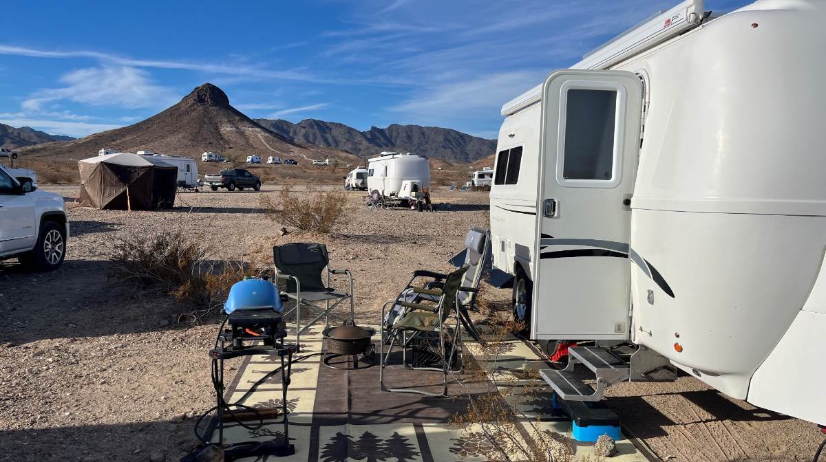
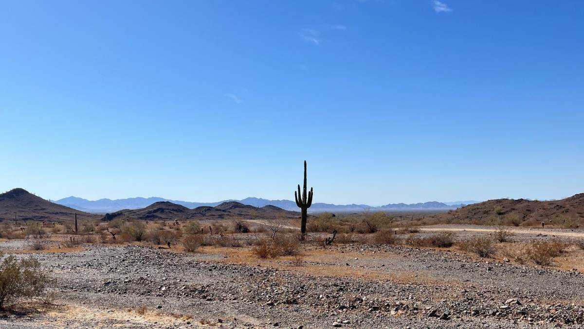
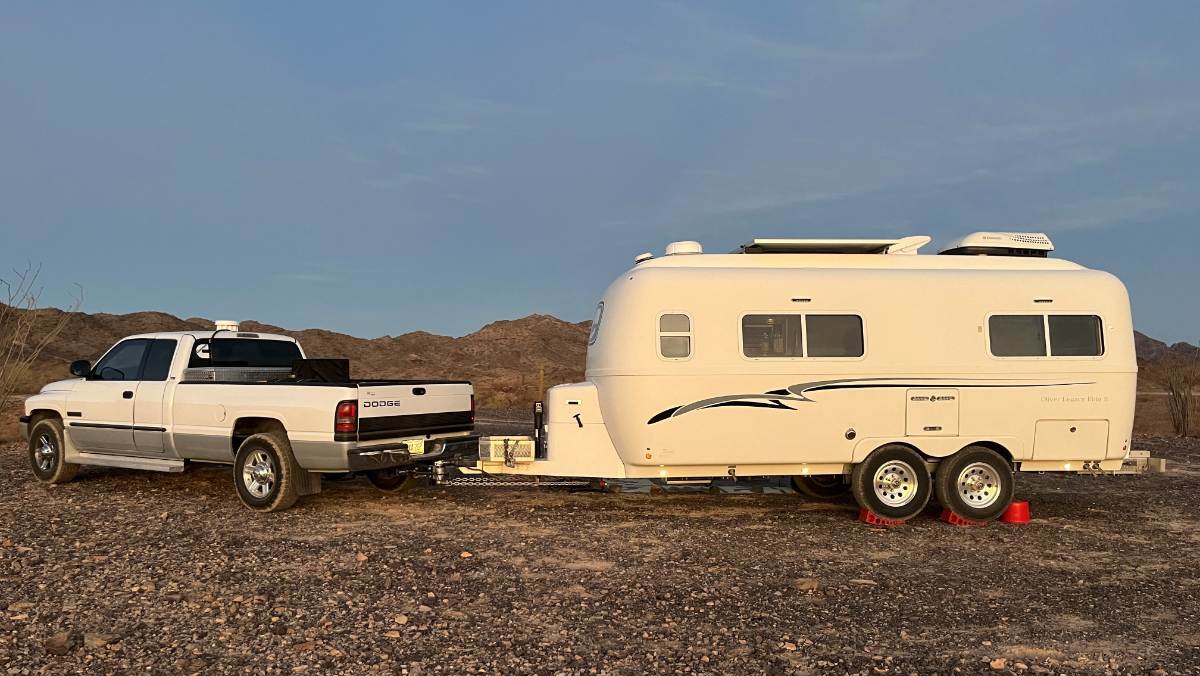
Who's going and when? The Q Big Tent runs Jan 17-25. The Fiberglass RV Gathering will run from February 6-9. I have time off work second half of Jan through first week of Feb and we'd like to visit for a few days when other Oliver Owners are there. Love to meet old friends and new! We weren't so much for Dome Rock (pic1) last year except for meeting Oliver owners! It's a bit crowded with the constant whine of nearby I-10 (and too many little Casitas)! Later we stayed several miles up Plomosa Rd NE of town. It was quiet up on the ridge with great views (pics 2-3). Hope to meet y'all there! 😎
1 point
-
Chris, you may want to do what I did to #113, now that our hulls are 10 years old! And your grounds look more corroded, seeing the color of the copper. I removed each and every one, trimmed the wires back 1/2” and stripped them for clean fresh copper, retighten good!1 point
-
On all my trailers I cut the ground wire and bolt it to the frame not far from the hitch. Makes it easy to test and repair when brake and/or lights issues arise.1 point
-
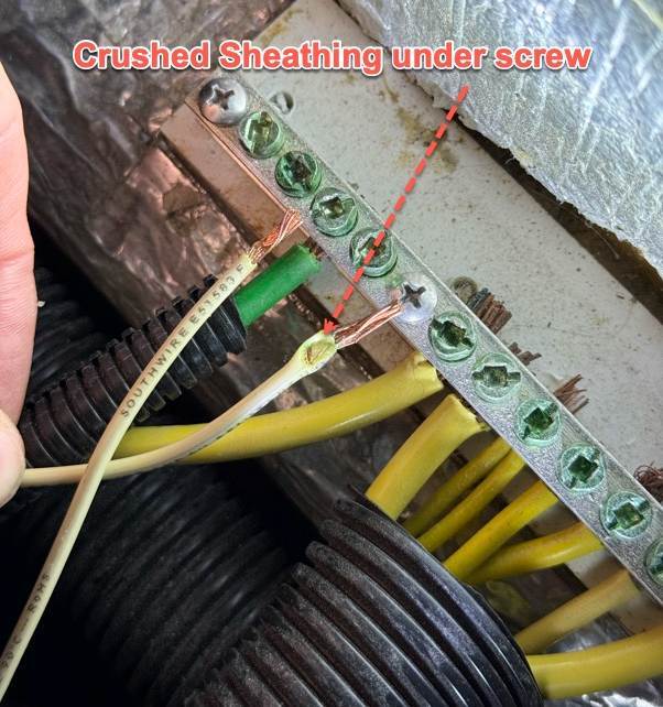
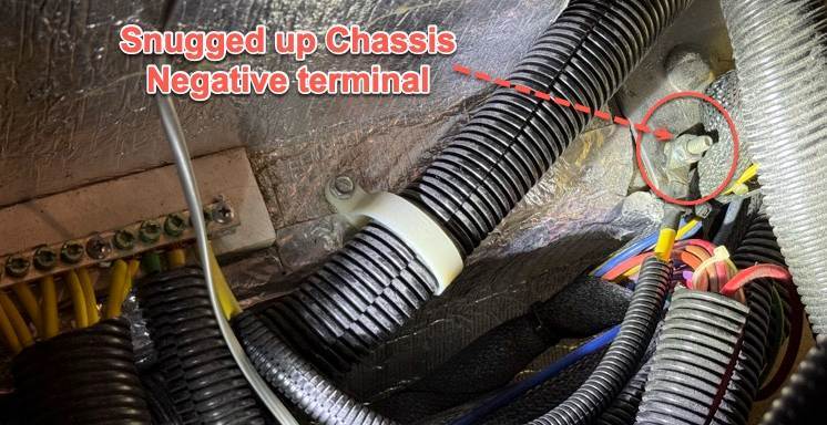
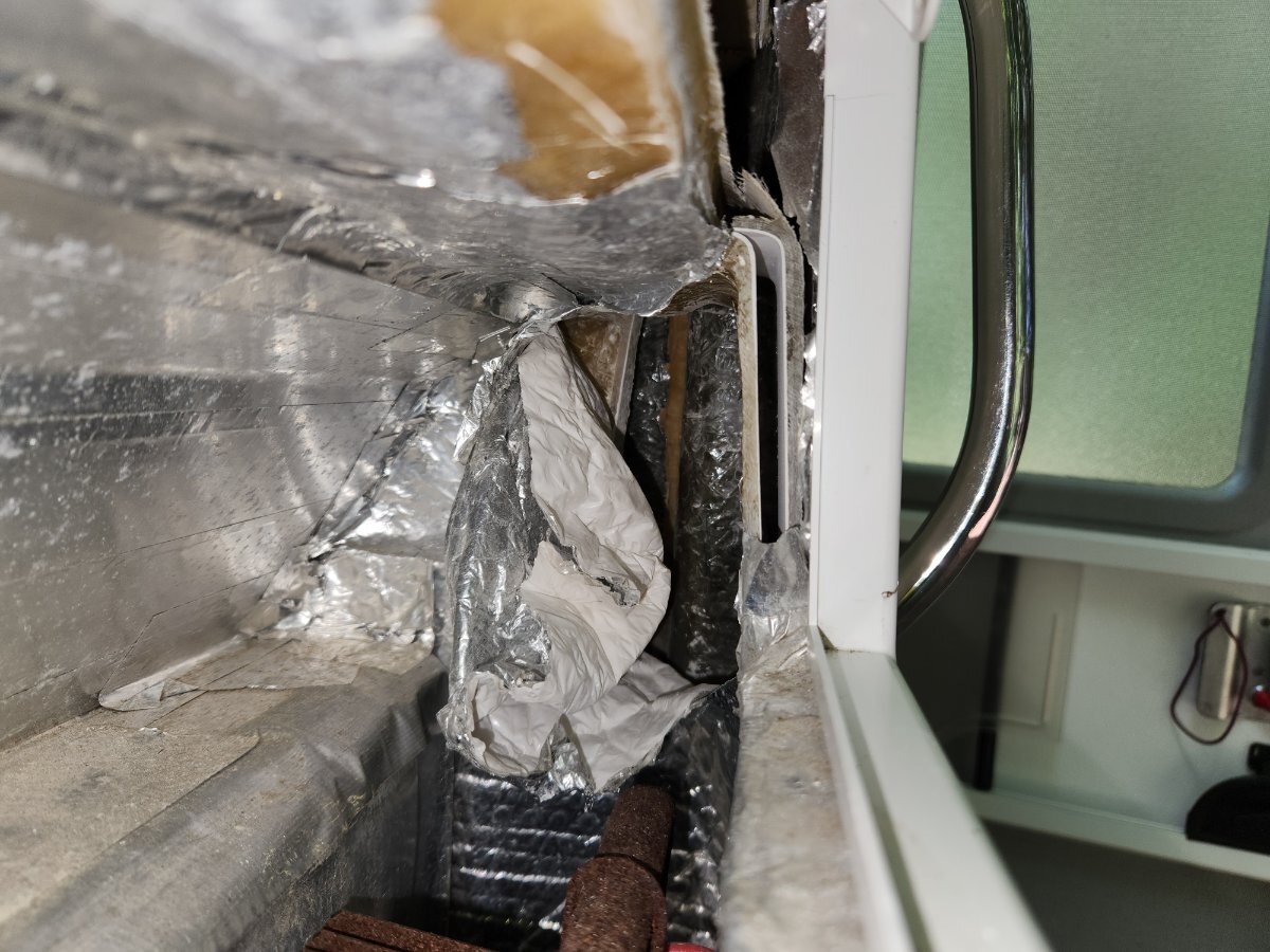
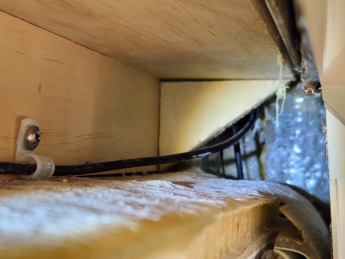
Well, I cannot believe it took me this long to find the issue with my intermittent brakes after Oliver failed to put on new axles for me last year. Since then I've been dealing with my RAM disabling the brakes periodically. No rhyme or reason... (known to me). At least three or four of you folks here would have found this sooner than me, I'm sure of it. As suggested by some, I verified all ground wires going inside the trailer from the brake bundle on the drivers side (only for snugness). I have even replaced all brake bundle connectors, some I did twice just to be sure (today). But the good thing is I learned a great deal, and I found a ton of wire connector corrosion along the way. Even the 7-pin connector (now replaced) was not looking good. But what I DID NOT check was the actual copper wire condition going INTO the negative/ground bus-bar inside the trailer. Well, after checking, re-checking, re-checking again all brake connectors today, and verified voltage to all brakes, I think I found what someone at Oliver had done. See, when they initially removed my axles from #110 last year, in hopes that the new axles would fit my frame (that's another thread), they slapped my old axles back on, and hence re-ran the wires back into the trailer (creating the new issue). Sure I checked for snug negative screws, but I never actually pulled out the wire from the bus-bar. Look what I found today. After fixing this "mess", and ensuring the sheathing was not inside the bus bar, my third test drive for the day was a success, but who knows, I've driven four hours in the past, before my truck was bitching about low voltage for the brakes. This had to be the issue, I hope. I was also able to snug up the main nut to the chassis ground, although I know that was not the primary issue. Sigh!
1 point
-
Never had an issue with a single BattleBorn 100AH in our LE2 since 2021. Believe our battery use would be considered low stress. Just purchased two new 100AH BB during Black Friday sales event because of our past experience with BB before this video came out. I have been careful securing the battery and all connections are tight. Will start monitoring Battery Temperature with our Victron shunt. .1 point
-
@John Dorrer. The RV-Safe alarm we ordered actually comes with a Wago or Wago-look-alike connector! ☺️1 point
-
FINAL DECISION: Well, we decided against any shutoff options and went with the RV-Safe alarm like the OEM one that came in our hull #941. Thanks to all for your ideas and thoughts. Barb1 point
-
Given these detectors have a Silence/Test switch on the face, I'm not adding a switch and don't believe it's a good idea given it can be left off when needed. Is there a brand preference? Meaning are some brands more effective than others? The brand we have now is RV Safe as pictured above and this link: https://www.amazon.com/RV-Safe-RVLP-2W-Propane-Alarm/dp/B08VCBH66H/ An Atwood detector was OEM on our hull many years ago, reason OTT cut that big square hole in the fiberglass. This model is a replacement that I believe fits recessed into that spot (though I have not yet verified dimensions). It also has a strength readout. Hopefully it's not too bright under the dinette but the RV Safe model has quite a bright green light too. https://www.amazon.com/gp/product/B0F8GMBQ5B/ I'm not sure I trust a built-in "Test" button! We have a LP torch Chris uses for cooking (for melting cheese and browning foods). It will release LP without igniting and when lit it should produce CO. Perhaps a real test is in order time to time. I should wear ear protection and I'll report back when I get around to this test. So, does anybody know that one brand is better at detecting CO and LP than another?1 point
-
Is there a regulatory authority over RV accessories, or would lithium battery suppliers fall under some other regulatory jurisdiction? Not really sure how aftermarket lithium batteries are categorized. Accessories, DIY, OEM, etc. They aren’t specifically dedicated to vehicle or RV markets. Had never really thought about it before.1 point
-
and to @Geronimo John, who nicely wrote, “Are we there yet?” My answer is “Yep” but perhaps not yet at $500 mark (unless one LiTime 230 Ah does ya). Which btw just beats four big heavy lead-acid batteries of the day!1 point
-
Always working....labor of love :)1 point
-
Still working on that rig?! Who isn’t? Come see us in Prescott too. Say hi to Wen. 😎1 point
-
Count us in :)1 point
-
In my eyes, John Davies was a pioneer in DIY efforts. I have often referred back to his wisdome and approach when doing my own. Sadly I have neither the tools, equipment or skills as this great craftsman. But I sure can gain insights on how to do things in our trailers from his efforts. Geronimo John John Davies Posts Index (April 2023 Version).docx1 point
-
Oops, 2021. Will change Thanks, Jamie1 point
-
This is NOT the greatest pic below of the frame I made for a switch and the place that the frame was located - just inboard of the detector under the dinette seat. I used two part epoxy and left it dry overnight and it has been in that spot for the past 7 years. Make special note of ADKCamper's note above about "flagging" this or any other safety unit when you have it out of service. Bill 2 inch square bracket for propane switch.jfif1 point
-
Yes... I have used SAE "2-flat" rubberized connectors for 12v dc devices that I might want to disable/remove easily for service, access, replacement, etc. Pay particular attention to the polarity as shown above... so that the "live" end connected to the trailer wiring harness has its positive "+" terminal covered in rubber (and the bare "-" terminal is exposed). I also use the small 2-pin SAE rubber covers to protect the trailer side of such connections when the 12v device has been unplugged. The rubber cover hangs on the wire right behind the trailer-side connector, ready to cover up the live female side of the connector. Also pay attention to the current rating of these connectors. This particular one is a Hopkins 47965, has 16 gauge wire nominally rated at 10A. Many such 2-flat SAE connectors are also rated at 10A max. Looking online a bit harder you can find 2-flat SAE connectors with 12 gauge wire if needed, Just as when you pull the fuse to silence a safety device such as this, be careful to flag the device as disconnected (e.g. hang some surveyer's "tell-tale" tape so it is visible sticking out from under the dinette seat cover) and take positive steps to restore the device to service as soon as possible.
1 point
-
1 point
-
A follow up to my previous post. FWIW. This issue is exactly why I choose three separate batteries instead of using only one. If one fails or even two fail during a trip, I can easily switch to the remaining good one(s) in the field and not have to make a faulty quick decision in order to provide heat or to keep my compressor fridge running. Anyway something to think about when in this case choosing batteries.1 point
-
John, your pics of the spot you stayed there on the ridge do not do that view any justice, you found a winner there with unbelievable views, will definitely see you there next year….2026/2027!1 point
-
Going to finish my Turbro install soon. I have next week off. I hadn't planned on adding the Cielo thermostat, unless after a season of use it is deemed necessary in our use case. Humidity is rarely an issue in our travels. Also, @BigTexas nicely wrote-up a concern that was in the back of my mind...1 point
-
I just bought a supply of popcorn for the show🤣1 point
-
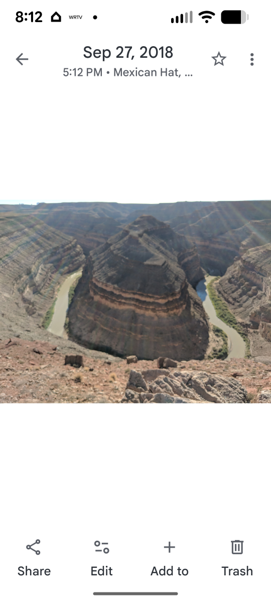
Goosenecks State Park, UT, not to far from Moab. Camped on the rim for $10/night. High above the San Juan River. You get an option, campground or along the rim. No brainer.
1 point
-
With all of this good info @jd1923 and the other thread on greasing the head, I decided since the Oli is down for 3 months before we take her back out, I would Pull the jack apart and grease everything in the head, tubes and drive screw. A few thing I learned/did. 1. The helical drive gear on the Curb side motor had a small amount of wear, the other two were not visible. I think that I hit the top more often since it is hard to see across the trailer specially with the mud flaps added. 2. The 3 set screws holding the head to the shaft had red thread lock. Used a heat gun to help loosened them. 3. The 2 carriage bolts holding the Rear jacks to the bracket where Stainless steel with a two way lock nut (two dimples on nut). They used so much force to putting on the nut on that it gulled the thread inside. It took 80-100 ft/pounds to get the nuts completely off and was a rear bear. I got one off by my self, but it was tough holding the carriage hold in while trying to remove the nut. I ended up getting help with the others from my son. The last nut was so hard just to hold it in, when we got the nut far enough off we used a 1/2 open end wrench on the square of the carriage head. 4. The chalk on the outside of the trailer adhered to the jack , but not the trailer. when the carriage bolts were remove, the jacks just dropped down down about 1/4" and then I just lifted it back up through the whole. I luckily didn't find any signs of water inside the trailer. 5. The three 1/4" Socket head cap screws holding the outside tube to inner assembly had Gray thread lock, they were tight to remove but doable without heat. 6. The drive screws came out easily with two 1/2" dowels. 7. The grease between the tubes was clean on the top, and dirty on bottom. All of the grease was getting hard. 8. All of the drive screws had some grease on them, two had bare minimum, and one had slightly more. The front jack had a little more grease than the rears. 9 The rear jacks I remove the motor and left it in the trailer. So I could clean and partially grease the assembly on the work bench. then finished greasing during assembly in the trailer with redline CV2 . 10. I remove the whole front (tongue) jack as a unit and did the cleaning a greasing on the work bench. The front jack was little more time consuming to clean since the power wire run up into the bottom of the case and then wires run up through the top of the case. I removed the switches and light from the plastic case top and got it out of the way so I had more room to clean and grease the case halves. 11. I did re-grease in between the tubes, just because they did at the factory. I know it may make more work for me latter. 12. I really liked butyl tape idea for sealing the tube back in the trailer . I put a little more on the tube than @jd1923 and formed a slope on the bottom side. When the tube was inserted the butyl went all the way through the hole in the trailer. I work the butyl from the top making sure it was pressed tightly to the and in the hole. I did not caulk the bottom, I used butyl added a little more to the bottom to completely seal the bottom with 3/8 per side. I am not sure how well the butyl will continue to seal on the outside, but it couldn't be any worse than the caulking job that was done at the factory. 13. I did replace the original Carriage bolts with steel, Nylock lock nut, and lock washer. 14. I used an enamel pen marker making a mark 1-1/2" from the bottom of the inside tubes for a stopping point. Instead of allowing the foot to come too far up. I started with the Rear curb side jack (12hours), then the Front jack (7hours), lastly the Rear street side jack (5 hours). I also called Baker and receive 3 gaskets for free. before starting the project. I need one for the front. the other came off easily. I also use liberal amounts of redline CV2 grease on everything. Thanks for listening1 point
-
Just called BattleBorn and left a message for technical support. Had a BattleBorn battery in Ollie for years without issues. I have had such good performance out of BattleBorn batteries, just purchased two more 100AH batteries during the Black Friday sales event. Will see what they say and post.1 point
-
Pat - It does seem likely that the notes you refer to have to do with the brake system. Primarily this is because I assume that it is a "mis-type" and should read "liner gone" and that the only "electromagnet" that exists in the Oliver is the one found in the brake drum. Can we assume that you are also experiencing a lack of trailer braking? Bill1 point
-
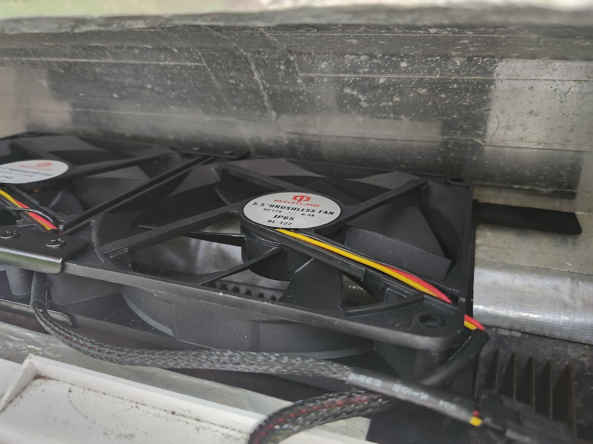
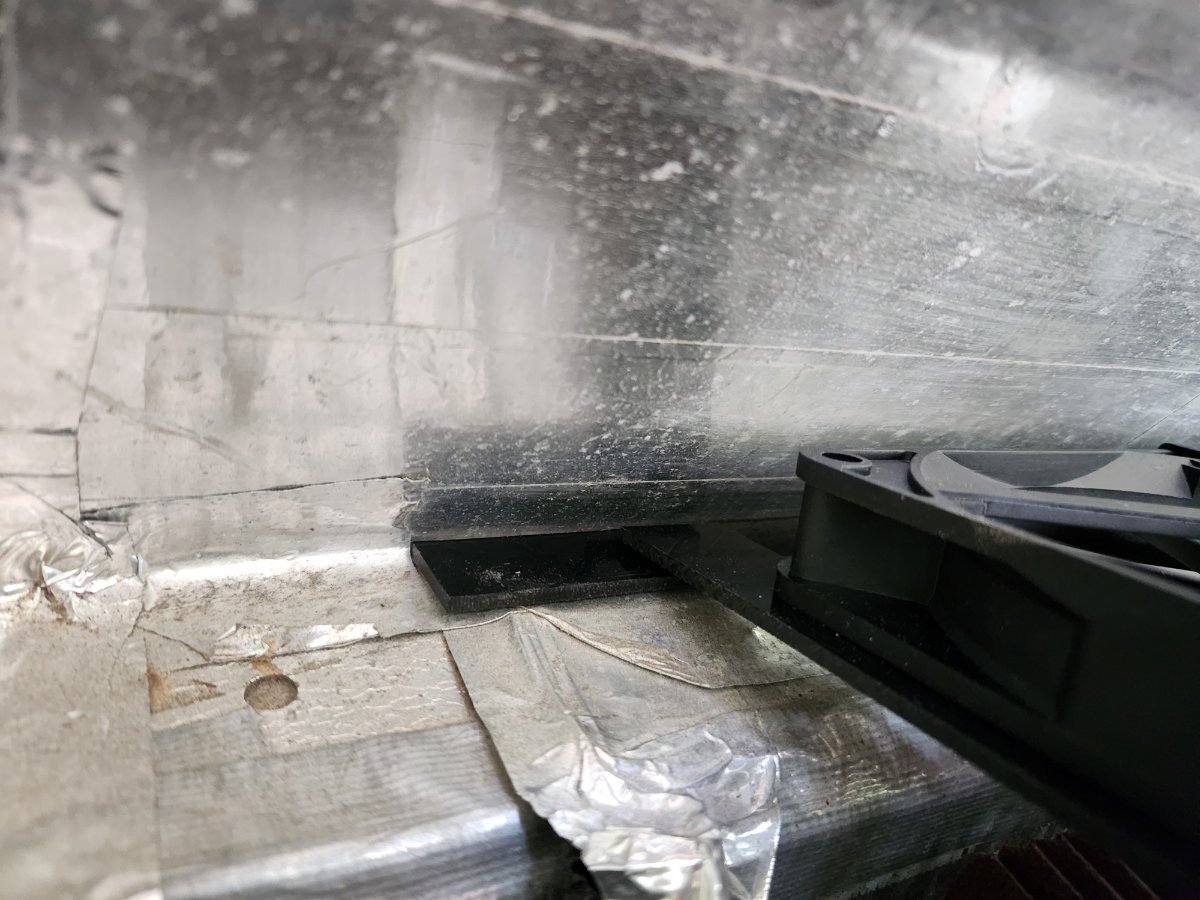
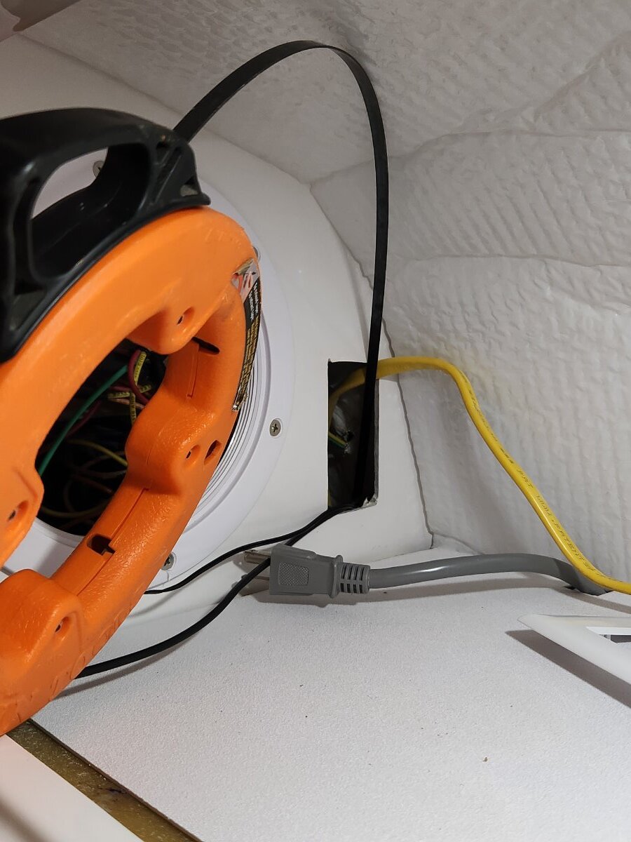
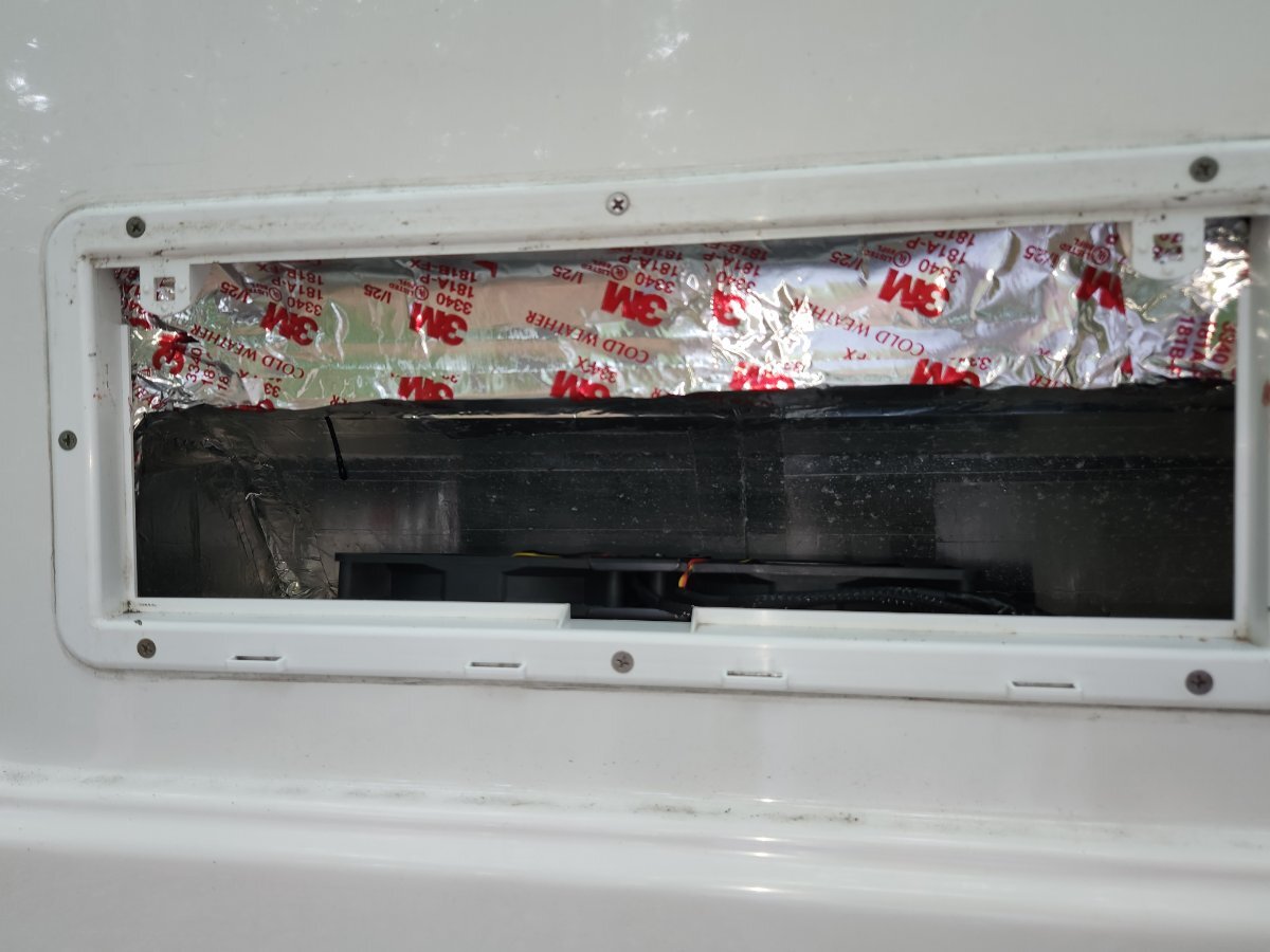
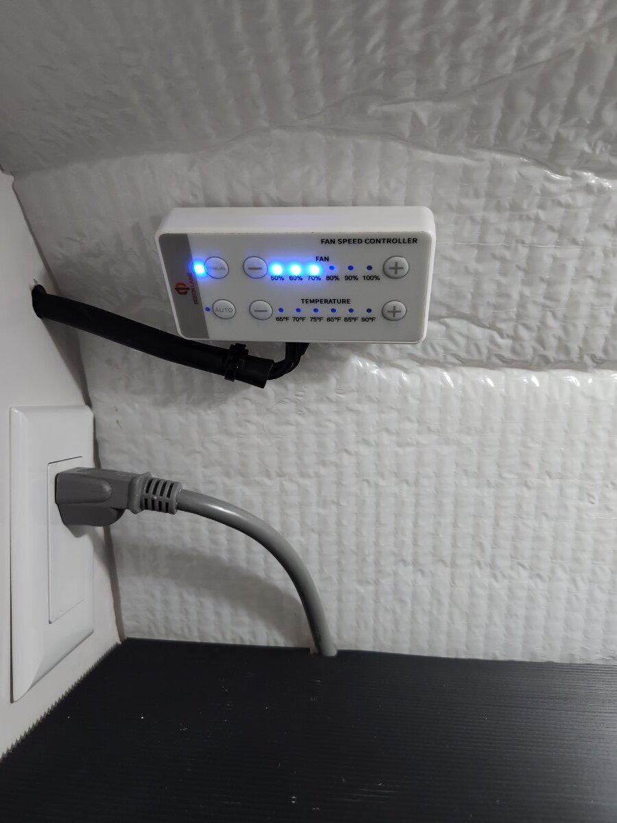
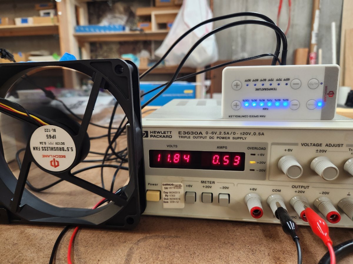
Finished the install. A somewhat complicated project but definitely helped by all the great info posted in this thread and elsewhere. Thank you very much! To summarize: As the brackets supplied by Beech Lane weren't going to work in our 2021 LE2, hull #701, I rearranged the fans to bring the cables to the front and then fabricated a mounting bracket from some ABS sheet I had in my shop. ABS is great stuff, nearly indestructible and easy to glue with ABS glue (a mix of acetone, MEK, and dissolved ABS. Don't drink it.). Nothing else works, including epoxy. The fans and bracket sit atop the space, let's call it a plenum for simplicity, in which the 'fridge coils reside. The rear longitudinal piece, which has foam tubing on it in the final version (not shown) sits snugly in the vee of back wall. The tabs on the lateral pieces sit atop the hull honeycomb behind the grille surround and are screwed vertically into the honeycomb with 8x1 1/2" stainless sheet metal screws. The fan assembly isn't going anywhere. The three cables from the controller run through a new 1/2" hole drilled in the cabinet wall and downwards. One you find the right spot with the fish tape it is straightforward to push the cables & tape downwards until they are visible from inside the plenum. The fan power cable and connector are routed to the right, wrapped in electrical tape, and secured against the wall using 3M 3340 HVAC tape. From there it passes through the bubble wrap insulation and up to the area to the left of the upper cabinet, behind the 6" round access panel and switch panel. It is necessary to pull the bubble wrap insulation and original HVAC tape away to access this space from inside the 'fridge upper vent area. Meanwhile, the controller and fan power wires are routed across the top of the vented area and secured to the plywood. It is necessary to remove a piece of foam secured by HVAC tape to access this space. From there the power wires are routed down the aft side of the 'fridge coil space and secured with cable clips. As suggested by @RonbrinkI spliced the power cables into the existing +12V and ground by removing about 1/4" of insulation, wrapping the fan power wires around the 10 ga. 'fridge power wires, soldering them in place, then covering with shrink wrap and electrical tape. The power cable supplied by Beech Lane is too short to reach all the way down to the bottom of the 'fridge so you'll need to add length if you go this route. I used 18-2 cable from a big box store. The OEM Beech Lane cable is like 22-2 and somewhat difficult to solder, so be forewarned. The controller & fan power wires were secured with cable clips and 8x1/4" stainless sheet metal screws. The temperature sensor was provisionally mounted in the upper aft part of plenum and secured with 3M HVAC tape. Not sure whether that's the best place or not yet, it may be better off further down the plenum. The pink foam which had formed the front wall of the uppermost part of the area behind the upper grille was replaced and secured with HVAC tape. Last, the controller was mounted to the rear wall of the cabinet using heavy duty Velcro. I used two 1/4" wide strips of hook material on the back of the controller and two 1" squares of loop material on the wall. There's no need for more than that as the controller weighs very little and using more hook material will just tend to pull the loop material off the wall if and when you need to move the controller. We'll see, we're not going anywhere 'hot' until February when we'll be in central Florida. Bench testing showed about 0.6 A draw, or the amount shown on the fan label, when the fans were set to run at 100%. Thanks to everyone and I hope this helps. Tim
1 point
-
Ours had what looks like the same single fan, but on the top of the coils, easy to remove (see pics on page 1, first post). Yeah, leave it there and install the dual Beech Lane fans!1 point
-
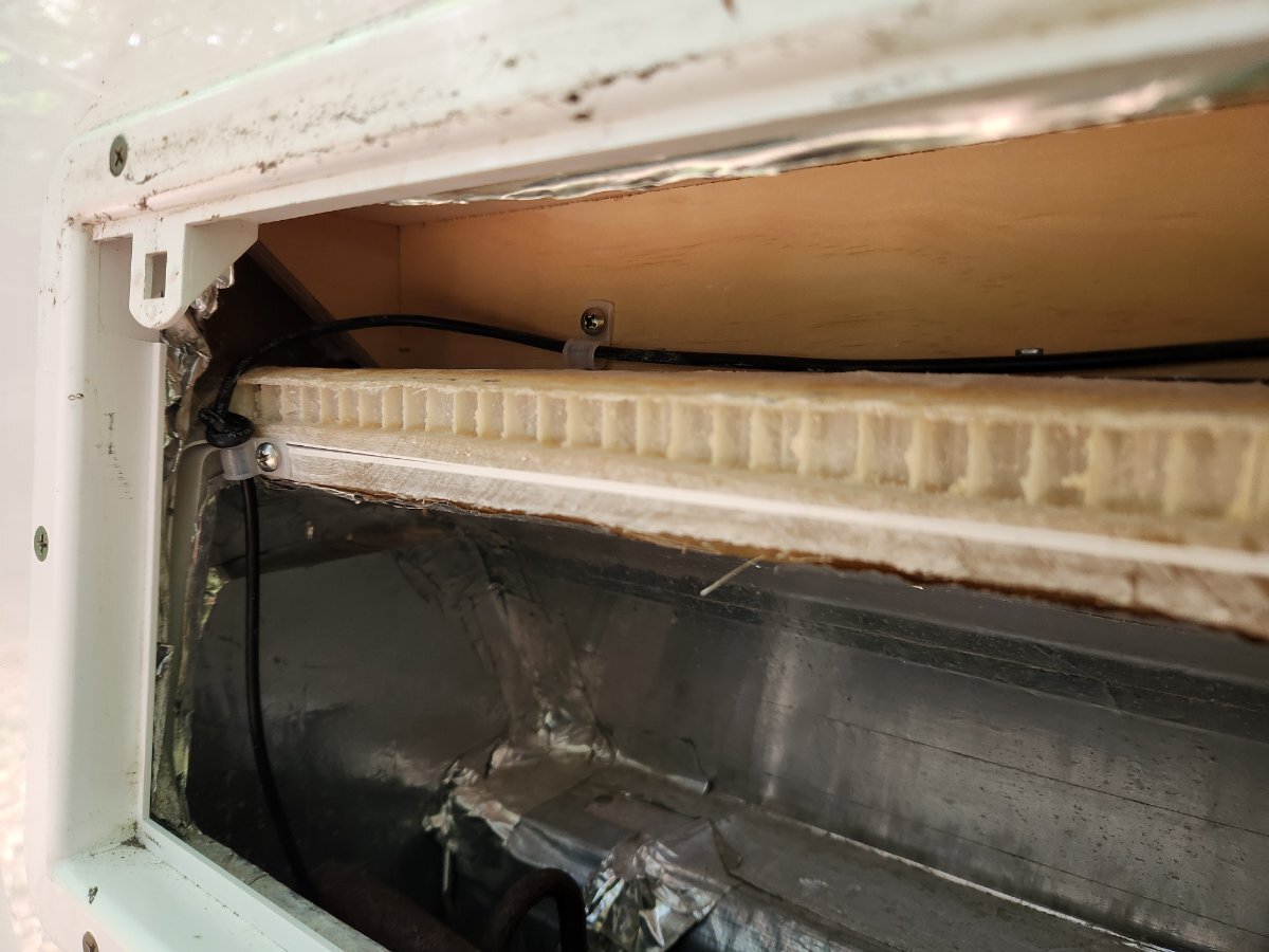
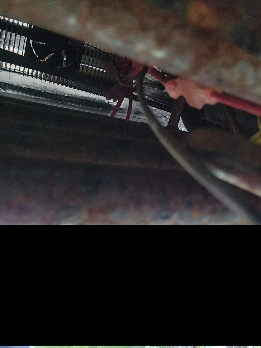
I'm continuing to work on the Beech Lane aux fan install. I will post pics when done. Meanwhile I discovered our trailer already has a fan on the 'fridge coils! Not sure it is operational. I don't think it is very effective. The clue was the black & red wire pair running from the electronics module on the back of the 'fridge upwards towards the evaporator coils. I did not RTFM to determine whether the fan speed is controlled by the 'fridge. The Beech Lane fans should make this redundant but getting it out would require removing the 'fridge, which I'm unlikely to do. Photo is looking up from inside the lower access panel. Tim
1 point


.thumb.jpg.e34bf01ef7f7d5e99ad31856d45afbeb.jpg)


.jpg.623219bf7c8f2451bf2d4fa8240146c9.jpg)
-
Recent Achievements
-


")


")

